Members USBIF USB 2 0 Compliance Testing How

Members USB-IF USB 2. 0 Compliance Testing How to design, test and debug your products for success. Jim Choate Agilent Technologies

Outline • • • USB 2. 0 Basics Agilent’s USB 2. 0 Solution Design challenges Common compliance pitfalls What are Waivers? Advanced Debug and Testing with the 9000 series Oscilloscope • Conclusion / Q&A
 2. 0: • All")
USB 2. 0 Basics – General Universal Serial Bus (USB) 2. 0: • All USB specifications are owned by the USB-IF (Implementers Forum, Inc. ) • USB 2. 0 is an EXTENSION of USB 1. 1 • USB-IF states USB 2. 0 is the CURRENT ver. of the USB 1. 1 is available for historical reference only. USB 2. 0 Has 3 Transfer Speeds USB 2. 0 HS USB 1. 1 LS/FS – Low Speed (LS) = 1. 5 Mbps – Full Speed (FS) = 12 Mbps – Hi-Speed (HS) = 480 Mbps USB 3. 0 Has 1 Transfer Speed – Superspeed (SS) = 5 Gbps For more details on the USB 3. 0 specification refer to the webinar: USB 3. 0 Superspeed PHY Testing Challenges: Verify your 5 Gbps design to the specification http: //www. techonline. com/learning/webinar/215400047 USB 3. 0 SS

USB 2. 0 Basics - Architecture • USB Architecture Host / System Down stream Hub Up stream Devices • • Differential Signal Max USB cable length of 5 m Up to 5 Hubs Data from PC to the device is called Downstream • Data from device to PC is called Upstream USB Cable + Shield VBUS D+ DGround

USB 2. 0 Basics - Signal Rates & Levels *High Speed USB edge rate compliance measurement method and pass/fail criteria have been changed. This will be explained in the compliance requirements section.

Host test requirements http: //www. usb. org/developers/docs#comp_test_procedures

USB 2. 0: Logo compliance for Quality • With 480 Mbps, higher quality electrical signals are essential • The market requires all USB products meet the specification by passing the tests. The USB 2. 0 Compliance Tests are mandatory When you pass the tests, you… The HS Logo • Can use the High Speed USB 2. 0 Logo • Will be listed on the Integrator’s List The FS/LS Logo

Compliance Workshop Test Suites • USB 2. 0 Interoperability Gold Suite • Interoperability with “gold tree” components • USB Command Verifier • USB 2. 0 Electrical Test Suite • • Signal Quality Testing Receiver Testing Packet parameters EVM Test Suites • USB 2. 0 debug suite • 1: 1 Interoperability System Suites • Staffed and equipped by product vendor

Outline • • • USB 2. 0 Basics Agilent’s USB 2. 0 Solution Design challenges Common compliance pitfalls What are Waivers? Advanced Debug and Testing with the 9000 series Oscilloscope • Conclusion / Q&A

Agilent USB 2. 0 Solution • Test all aspects of your USB product using Agilent USB test solutions • At its heart: N 5416 A USB 2. 0 Compliance Test Software Additional USB testing products: • N 5417 A USB OTG Test Fixture • N 5464 A/B USB Protocol Triggering and Decode • E 2649 A High speed test fixtures • E 2646 A Low/Full speed test fixture • Infinii. Max probes • Infiniium 90000 and 9000 series scopes

USB Transmitter testing The worlds most popular USB test solution joins with the Infiniium 9000 series scope • Same automation and ease of use • NEW protocol analysis and triggering N 5416 A USB 2. 0 Compliance Test Application Agilent USB-IF approved compliance test with Matlab scripts NEW: Infiniium 9000 series Oscilloscope

Transmitter electrical test coverage Application automates all compliance tests and provides summary of all testing performed

Receiver Testing SE 0_NAK Mode • Test mode SW places DUT into RX test mode • Scope application auto adjusts amplitude and packet types to test RX Connection diagrams and integrated test procedures make setup and execution of testing simple • N 5416 A USB test application measures results automatically with histogram Industries only automated RX test solution

Receiver Jitter tolerance testing • Why Test USB 2. 0 jitter tolerance? • The N 5990 A option 102 provides unprecedented USB 2. 0 receiver device test coverage. N 5990 A USB test solution USB 2. 0 jitter tolerance test result

Completing the Solution: Fixtures and probing Automated drop/droop Infinii. Max Differential Probes: • The world’s best probing system • The right BW for the job N 2774 A Current Probe E 2649 A High speed USB compliance test fixture set 9000 Series ships standard with N 2873 A probes E 2646 A SQi. DD fixture • FS/LS Signal quality, Inrush N 5417 A USB OET

Outline • • • USB 2. 0 Basics Agilent’s USB 2. 0 Solution Design challenges Common compliance pitfalls What are Waivers? Advanced Debug and Testing with the 9000 series Oscilloscope • Conclusion / Q&A

Design Challenges • HS Signal Integrity – Trace and Driver Impedance – Proper decoupling • Current Draw – Operating current – Unconfigured current – Suspend current • Receiver Testing • Test Modes

USB Impedance Spec Explained • What does the spec say? • High-Speed Zo – cable = 90 +/-15 % – ZHSTERM = 80 to 100 ohms differential – ZHSTHRU = 70 to 110 ohms differential • FS Driver Impedance – Not HS capable: Zdrv = 28 -44 ohms – HS Capable: Zdrv = 40. 5 -49. 5 ohms

USB Impedance Measurement • 86100 C DCA-J paired with 54754 A Differential TDR module Test Bed PC ZHSTHRU 110 ZHSTERM 100 st TDR Te Fixture 80 70 USB Connector reference location BGA discontinuity

Proper Decoupling • Prevent signal integrity problems by understanding how to properly decouple power and grounds on your chip • Bulk vs filter capacitance – Electrolytic Bulk Capacitance C = I / (d. V/dt), size in u. F depends on max transients For example: I peak = 3 A, Vnom = 3. 3 V, 10% V tolerance, 10 usec delta time C = 3 A*(10 us/(3. 3 V*0. 10) = 90. 9 u. F => use 100 u. F Bulk cap* – Ceramic High Frequency Capacitance Typical values are 0. 01 u. F, 0. 1 u. F to 1 u. F depending on filtering frequency needed *note: Devices are required to limit inrush on hot attach by limiting load to 10 u. F in parallel with 44 ohms. Design

Proper Cap Selection and routing • Proper route/placement of capacitors • Choose the right kind of capacitor depending on it’s purpose – NPO (lowest ESR), X 7 R, X 5 R, Y 5 V Vcc Lowest pad inductance Gnd Standard method of Cap routing Vcc Gnd Much smaller ground loop

Measuring Device Inrush Current • Inrush is a function of device load on hot attach and hub port voltage/ESR • Spec limit = ~50 u. C • Inrush waiver built in to scripts • Limit inrush events by using sequential power on for controller logic N 2774 A Current Probe Inrush event time

Rise and Fall time • As designs move to smaller process technology the edge rates are increasing • USB 2. 0 specification limits RT/FT to 500 ps as measured at 10%-90% • Errors in consistency of these measurements due to: – Shape of signal edge 10%-90% variations – Noise – Amplitude variations – Probe peaking due to insufficient BW • Slow corners give 10/90 rise time that is slower than actual edge rate • RT/FT faster than 400 ps have observed • Oscilloscope AND Probe BW must be at least 2. 5 Ghz to accurately observe and measure these fast edges

Slew rate RT/FT methodology Slew Rate Method Design 10 -90% Method small ∆V of 10% and 90% = large ∆RT/FT Refer to http: //compliance. usb. org/index. html for the latest compliance test updates

Test Modes • Test_SEO_NAK • Receiver test mode • • Test_J Test_K Test_Packet Other tests driven by HSET using normal USB device requests – Example: suspend, resume, reset, etc

Outline • • • USB 2. 0 Basics Agilent’s USB 2. 0 Solution Design challenges Common compliance pitfalls What are Waivers? Advanced Debug and Testing with the 9000 series Oscilloscope • Conclusion / Q&A

Compliance Pitfalls • Failure to properly support USB suspend – Low power state required of all devices • < 2. 5 m. A (spec says 500 u. A = auto waiver) • Improperly report bus vs self powered if battery powered • RX Sensitivity failure vs Squelch • Backdrive • SW Driver loading sequence • Test mode not implemented

Compliance Pitfalls – RX Test • Misinterpretation of RX sensitivity and Squelch requirements has caused considerable confusion and discrepancy in test results • As you can see from the waveform at the right the artifacts on the transition and non-transition bits due to reflections are significant

Compliance Pitfalls – RX Test Compliance • Agilent uses a histogram function to standardize measurement of sensitivity and squelch thresholds • Other solutions require manual placement cursors based on “flat spot” on waveform • This automation greatly improves consistency of test results at workshops and test labs
 and Squelch (EL_16) Compliance • Please note that it is the")
Receiver Sensitivity (EL_17) and Squelch (EL_16) Compliance • Please note that it is the combination of EL_16 and EL_17 that validates the "transmission detection envelope" defined in section 7. 1. 4. 2 of the USB 2. 0 Specification

Outline • • • USB 2. 0 Basics Agilent’s USB 2. 0 Solution Design challenges Common compliance pitfalls What are Waivers? Advanced Debug and Testing with the 9000 series Oscilloscope • Conclusion / Q&A

Waivers • Some failures are due to measurement errors or non-critical failures • It is important to understand how the USBIF handles some types of failures • Automatic waivers – Always granted – May be built into test tools • Conditional waivers • Permanent waivers Non-Critical = No End User Impact Waivers

Waivers • The criterion for granting a waiver varies greatly and tends to be specific to the device. Some general factors used to consider granting or denying waiver requests are: – – Violation's effect on end-user experience Violation's affect on other USB product Market share of affected product Cost of corrective action to the vendor • Waiver decisions are at the discretion of the USB-IF Compliance Chairman and members of the Certification Review Board. Waivers

Waivers • Products with waivers post to IL and receive logo usage rights • General USBIF rule is waivers are not published • Design to specification not to waiver limits Waivers

Outline • • • USB 2. 0 Basics Agilent’s USB 2. 0 Solution Design challenges Common compliance pitfalls What are Waivers? Advanced Debug and Testing with the 9000 series Oscilloscope • Conclusion / Q&A

USB Protocol Triggering and Decode • Industries first on-scope USB protocol triggering and decode capability • Debug protocol issues • Trigger on different packet types • Test embedded designs • Isolate logical from electrical issues

Testing a Complex Bus Topology with the Agilent Infiniium 9000 Scope SATA Best 3 -in-1 Instrument IDE ULPI Scope: • Up to: 4 GHz BW, 20 GSa/s, 1 Gpts • Powerful triggering • Packed with rich features/analysis. Logic Analyzer: • 16 integrated channels • 128 Mpts std memory, up to 2 GSa/s • Precise analog + digital triggering USB 2. 0 In today’s world many subsystems are tightly integrated into multi function Embedded products: • USB 2. 0 interface • IDE parallel interface • SATA interface Protocol Analyzer: • I 2 C, SPI, CAN, RS-232/UART, USB, PCIe, 8 B/10 B • HW trigger and decode • First scope with multi-tab viewer • . Phy to protocol time correlation

Debugging multiple bus interfaces To LA Testing and debugging a USB 2. 0 to IDE and SATA adapter Diff probe on USB 2 LA on IDE E ID SB U TA • In the past each interface would need to be tested separately often with different types of equipment Today you can use the 9000 series oscilloscope to test it all with a single instrument SA • E 2649 A USB test fixture

Data read latency shown by read arrows
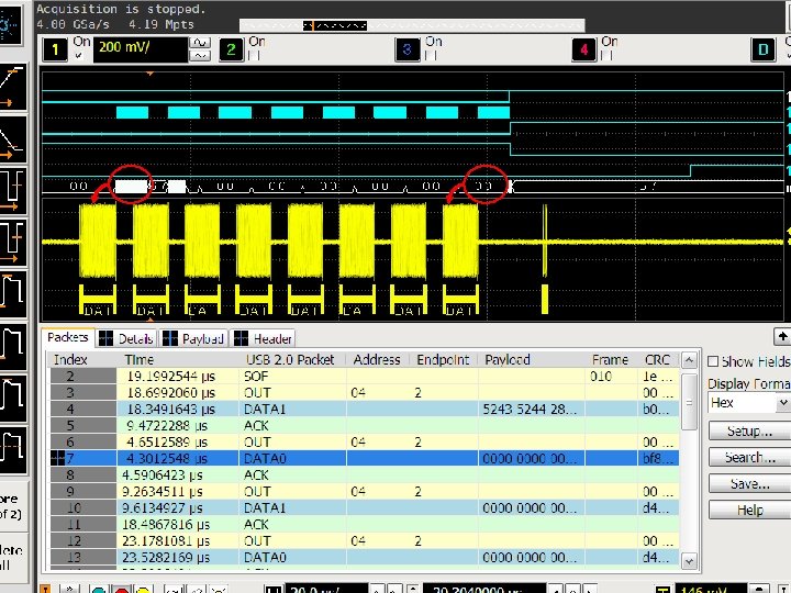
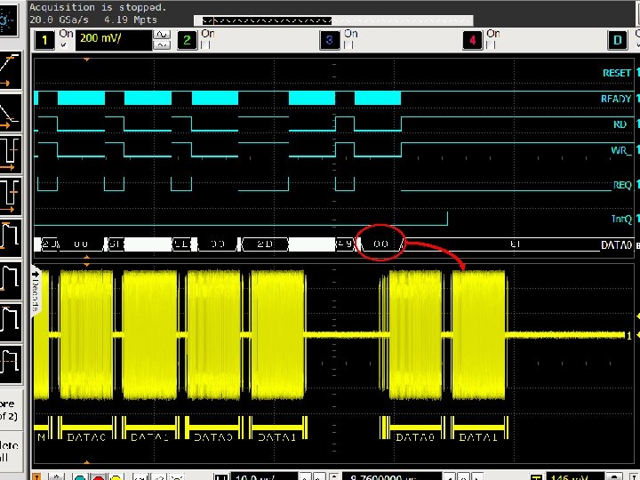

Advanced protocol triggers for debugging The serial search and real time HW trigger capabilities open a new realm of debug capabilities

Summary • USB compliance testing has grown over the years to address real product problems • Agilent has been a key partner with the USBIF in the growth and phenomenal success of the USB compliance test program • Agilent offers everything you need to test and certify all of your USB products • The N 5416 A USB Test Option offers the most accurate and highest level of USB test automation in the industry today • Agilent’s N 5990 A test automation sw takes testing to the next level with full USB 2. 0 jitter tolerance characterization • The Infiniium 9000 Series is the best 3 -in-1 instrument with scope, logic analyzer, protocol analyzer test capabilities Agilent Delivers the Worlds Best USB Test Solutions

Additional Information • Go to www. usb. org to get additional information on certifying your USB products • For specific updates to compliance requirements go to http: //compliance. usb. org/index. html • Agilent Application Note: Debugging USB 2. 0: It’s Not Just a Digital World • Go to www. agilent. com/find/usb to find more about Agilent Superior Signal Integrity Solutions and Probing for Your Applications

Miscellaneous topics • Workshops – Very good place for hands on training – Talk to experts • USBET – required for compliance, integrated into Agilent’s sw solutions • HSET tool issues – supports Win 7/8 with by disabling signed driver requirement (F 8 on boot) • Fixture standardization - USBIF will soon require probe less test method – using only SMA probing. - Agilent fixtures support this now.
- Slides: 45