
Medium Energy Ion Scattering Technique and Applications Dr

- Slides: 34
Medium Energy Ion Scattering – Technique and Applications Dr Tim Noakes STFC Daresbury Laboratory, Daresbury Science and Innovation Campus, Keckwick Lane, Daresbury, Warrington, Cheshire, WA 4 4 AD, UK
Overview • The medium-energy ion scattering (MEIS) technique • Applications of MEIS • • Surface structure High resolution depth profiling Thin film characterisation Characterisation of nanostructures • Possible future research areas • Summary
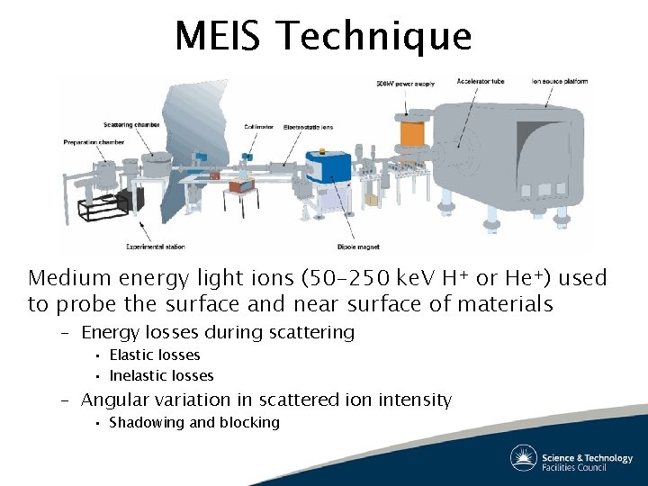
MEIS Technique Medium energy light ions (50 -250 ke. V H+ or He+) used to probe the surface and near surface of materials – Energy losses during scattering • Elastic losses • Inelastic losses – Angular variation in scattered ion intensity • Shadowing and blocking
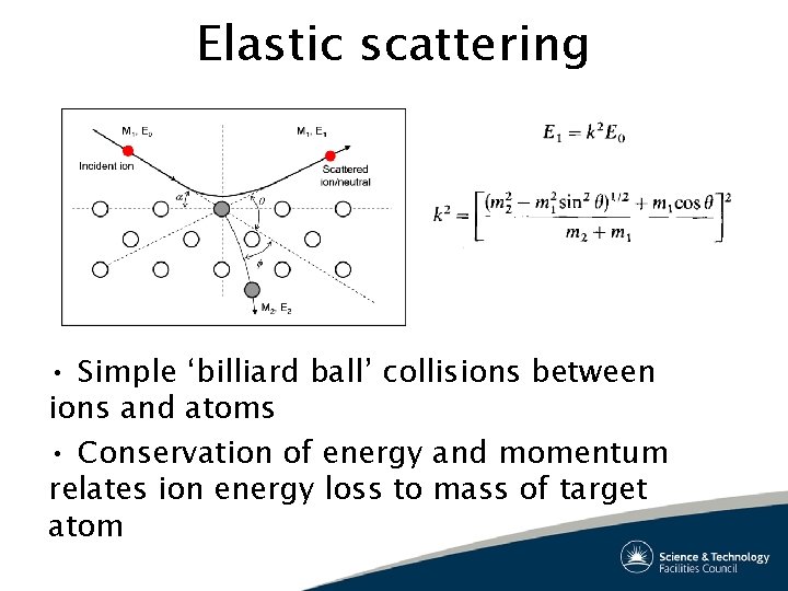
Elastic scattering • Simple ‘billiard ball’ collisions between ions and atoms • Conservation of energy and momentum relates ion energy loss to mass of target atom
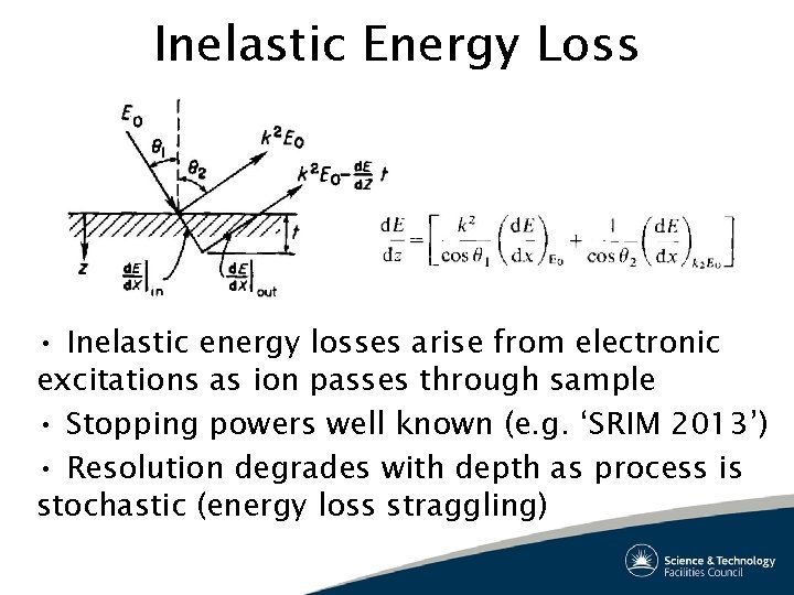
Inelastic Energy Loss • Inelastic energy losses arise from electronic excitations as ion passes through sample • Stopping powers well known (e. g. ‘SRIM 2013’) • Resolution degrades with depth as process is stochastic (energy loss straggling)
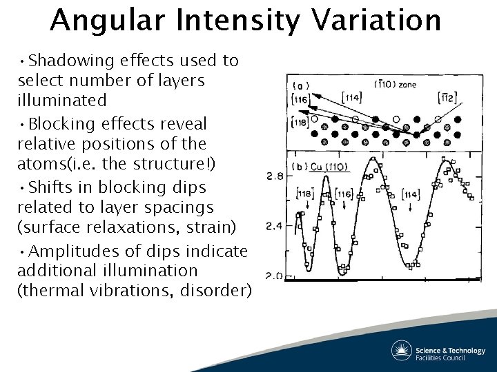
Angular Intensity Variation • Shadowing effects used to select number of layers illuminated • Blocking effects reveal relative positions of the atoms(i. e. the structure!) • Shifts in blocking dips related to layer spacings (surface relaxations, strain) • Amplitudes of dips indicate additional illumination (thermal vibrations, disorder)
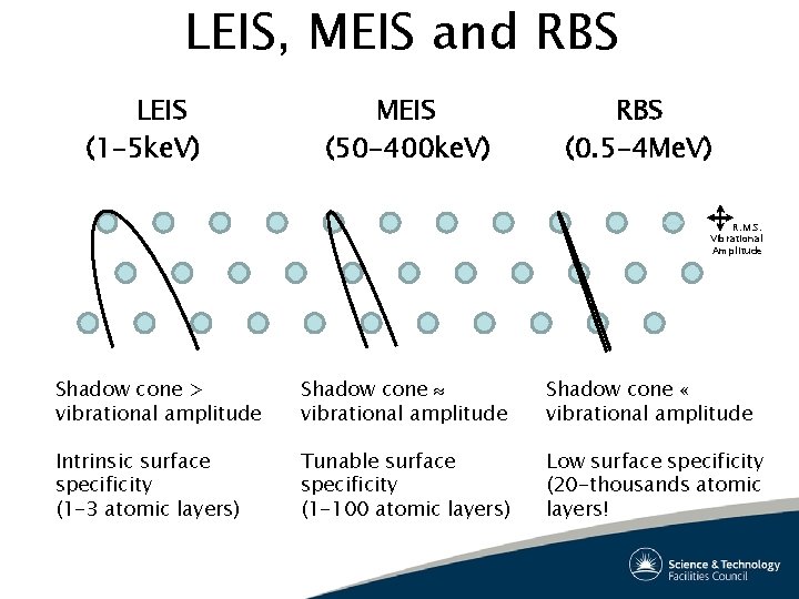
LEIS, MEIS and RBS LEIS (1 -5 ke. V) MEIS (50 -400 ke. V) RBS (0. 5 -4 Me. V) R. M. S. Vibrational Amplitude Shadow cone > vibrational amplitude Shadow cone « vibrational amplitude Intrinsic surface specificity (1 -3 atomic layers) Tunable surface specificity (1 -100 atomic layers) Low surface specificity (20 -thousands atomic layers!
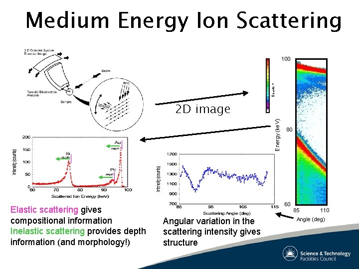
Medium Energy Ion Scattering Counts > 100 Energy (ke. V) 2 D image Elastic scattering gives compositional information Inelastic scattering provides depth information (and morphology!) 80 60 Angular variation in the scattering intensity gives structure 85 110 Angle (deg)
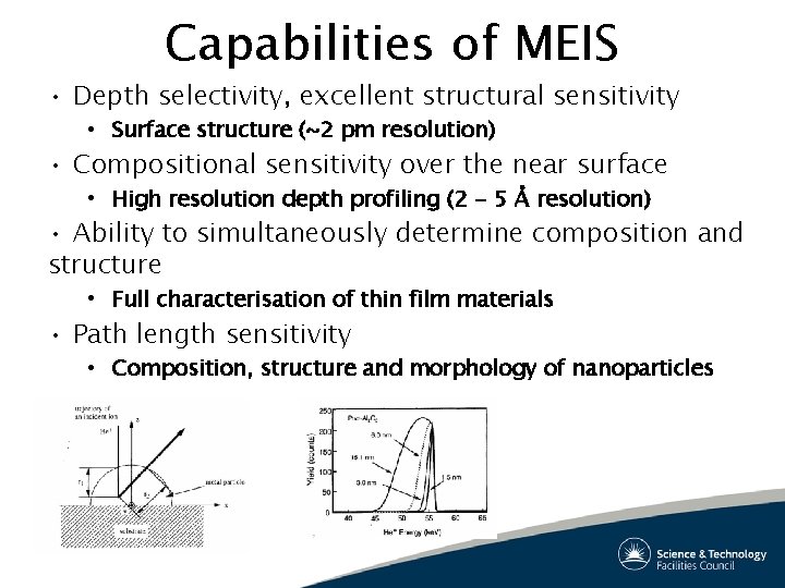
Capabilities of MEIS • Depth selectivity, excellent structural sensitivity • Surface structure (~2 pm resolution) • Compositional sensitivity over the near surface • High resolution depth profiling (2 - 5 Å resolution) • Ability to simultaneously determine composition and structure • Full characterisation of thin film materials • Path length sensitivity • Composition, structure and morphology of nanoparticles
Surface Structure Metals and metal alloys – Adsorbate induced reconstruction – Model catalysts – Complex metal alloys (e. g. quasicrystals) Semiconductor materials – ‘Ideal’ Schottky Barriers – III-V growth surfaces Oxides – Catalyst supports (e. g. Ti. O 2)
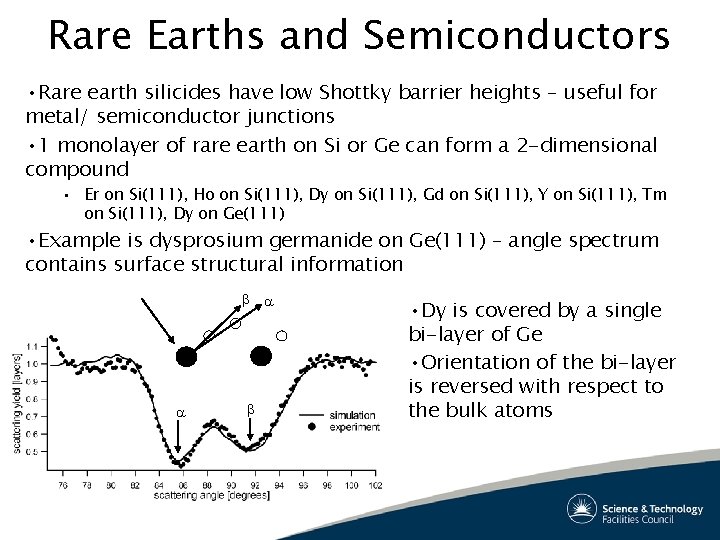
Rare Earths and Semiconductors • Rare earth silicides have low Shottky barrier heights – useful for metal/ semiconductor junctions • 1 monolayer of rare earth on Si or Ge can form a 2 -dimensional compound • Er on Si(111), Ho on Si(111), Dy on Si(111), Gd on Si(111), Y on Si(111), Tm on Si(111), Dy on Ge(111) • Example is dysprosium germanide on Ge(111) – angle spectrum contains surface structural information • Dy is covered by a single bi-layer of Ge • Orientation of the bi-layer is reversed with respect to the bulk atoms
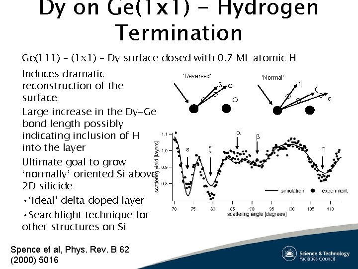
Dy on Ge(1 x 1) - Hydrogen Termination Ge(111) – (1 x 1) – Dy surface dosed with 0. 7 ML atomic H Induces dramatic reconstruction of the surface Large increase in the Dy-Ge bond length possibly indicating inclusion of H into the layer Ultimate goal to grow ‘normally’ oriented Si above 2 D silicide • ‘Ideal’ delta doped layer • Searchlight technique for other structures on Si Spence et al, Phys. Rev. B 62 (2000) 5016 ‘Reversed’ ‘Normal’
High Resolution Depth Profiling Semiconductor device fabrication • Ion implants for semiconductor devices • High- gate dielectric materials Structural materials • Oxide layers for Corrosion protection of light metal alloys • Construction materials • Automotive, aerospace, rail and marine transport applications • Biocompatible coatings for medical implants
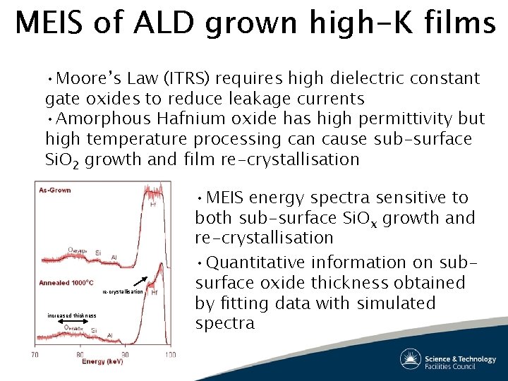
MEIS of ALD grown high-K films • Moore’s Law (ITRS) requires high dielectric constant gate oxides to reduce leakage currents • Amorphous Hafnium oxide has high permittivity but high temperature processing can cause sub-surface Si. O 2 growth and film re-crystallisation increased thickness • MEIS energy spectra sensitive to both sub-surface Si. Ox growth and re-crystallisation • Quantitative information on subsurface oxide thickness obtained by fitting data with simulated spectra
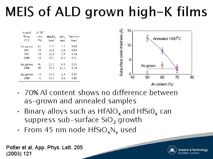
MEIS of ALD grown high-K films • 70% Al content shows no difference between as-grown and annealed samples • Binary alloys such as Hf. Al. Ox and Hf. Si 0 x can suppress sub-surface Si. O 2 growth • From 45 nm node Hf. Si. Ox. Ny used Potter et al, App. Phys. Lett. 205 (2003) 121
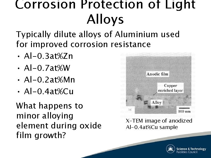
Corrosion Protection of Light Alloys Typically dilute alloys of Aluminium used for improved corrosion resistance • Al-0. 3 at%Zn • Al-0. 7 at%W • Al-0. 2 at%Mn • Al-0. 4 at%Cu What happens to minor alloying element during oxide film growth? X-TEM image of anodized Al-0. 4 at%Cu sample
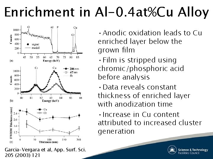
Enrichment in Al-0. 4 at%Cu Alloy • Anodic oxidation leads to Cu enriched layer below the grown film • Film is stripped using chromic/phosphoric acid before analysis • Data reveals constant thickness of enriched layer with anodization time • Increase in Cu content attributed to increased cluster generation Garcia-Vergara et al, App. Surf. Sci. 205 (2003) 121
Thin Film Characterisation Systems which benefit from the simultaneous elucidation of composition and structure • Metal-on-metal growth (giant magnetoresistance films) • Quantum well systems (III-V materials, metals) • Spintronic materials (metal/semiconductor hybrids)
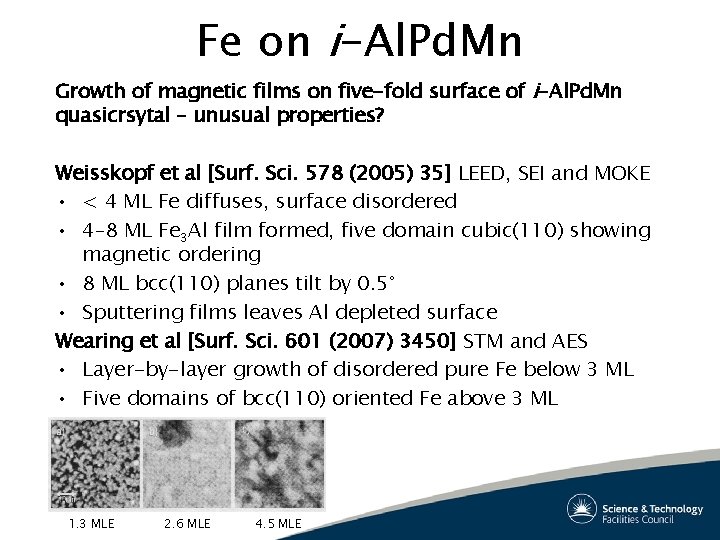
Fe on i-Al. Pd. Mn Growth of magnetic films on five-fold surface of i-Al. Pd. Mn quasicrsytal – unusual properties? Weisskopf et al [Surf. Sci. 578 (2005) 35] LEED, SEI and MOKE • < 4 ML Fe diffuses, surface disordered • 4– 8 ML Fe 3 Al film formed, five domain cubic(110) showing magnetic ordering • 8 ML bcc(110) planes tilt by 0. 5° • Sputtering films leaves Al depleted surface Wearing et al [Surf. Sci. 601 (2007) 3450] STM and AES • Layer-by-layer growth of disordered pure Fe below 3 ML • Five domains of bcc(110) oriented Fe above 3 ML 1. 3 MLE 2. 6 MLE 4. 5 MLE
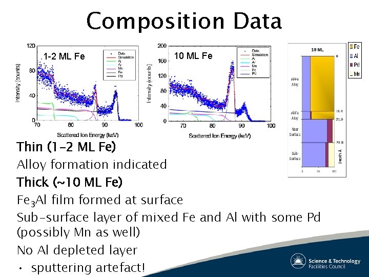
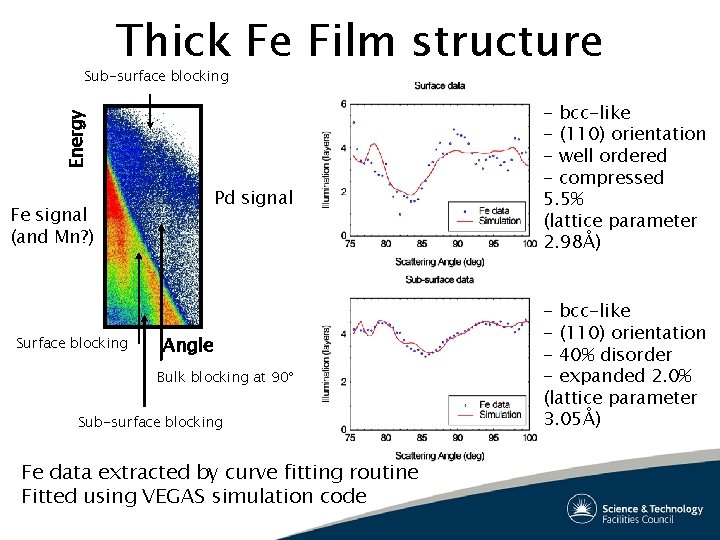
Composition Data 1 -2 ML Fe 10 ML Fe Thin (1 -2 ML Fe) Alloy formation indicated Thick (~10 ML Fe) Fe 3 Al film formed at surface Sub-surface layer of mixed Fe and Al with some Pd (possibly Mn as well) No Al depleted layer • sputtering artefact!
Thick Fe Film structure Energy Sub-surface blocking Pd signal Fe signal (and Mn? ) Surface blocking Angle Bulk blocking at 90 Sub-surface blocking Fe data extracted by curve fitting routine Fitted using VEGAS simulation code - bcc-like - (110) orientation - well ordered - compressed 5. 5% (lattice parameter 2. 98Å) - bcc-like - (110) orientation - 40% disorder - expanded 2. 0% (lattice parameter 3. 05Å)
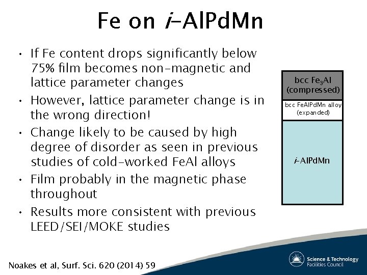
Fe on i-Al. Pd. Mn • If Fe content drops significantly below 75% film becomes non-magnetic and lattice parameter changes • However, lattice parameter change is in the wrong direction! • Change likely to be caused by high degree of disorder as seen in previous studies of cold-worked Fe. Al alloys • Film probably in the magnetic phase throughout • Results more consistent with previous LEED/SEI/MOKE studies Noakes et al, Surf. Sci. 620 (2014) 59 bcc Fe 3 Al (compressed) bcc Fe. Al. Pd. Mn alloy (expanded) i-Al. Pd. Mn
Nanoparticle Characterisation Topographical information • Single element clusters Compositional information • Bimetallic alloys (model catalysts) • III-V quantum dots Structural Information • All the above!
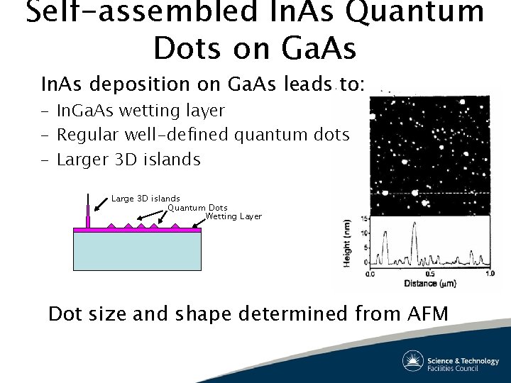
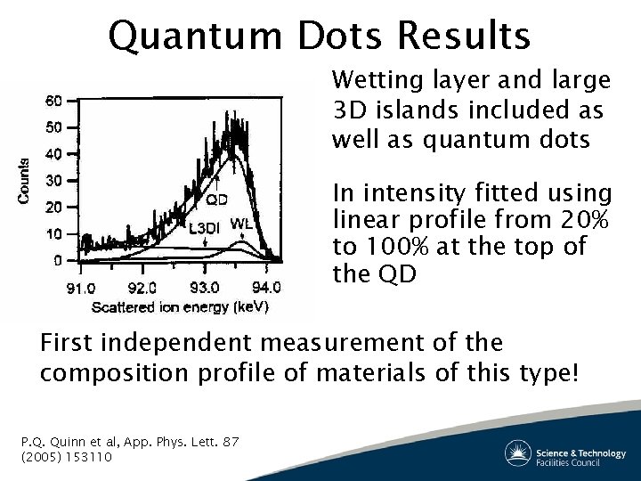
Self-assembled In. As Quantum Dots on Ga. As In. As deposition on Ga. As leads to: – In. Ga. As wetting layer – Regular well-defined quantum dots – Larger 3 D islands Large 3 D islands Quantum Dots Wetting Layer Dot size and shape determined from AFM
Quantum Dots Results Wetting layer and large 3 D islands included as well as quantum dots In intensity fitted using linear profile from 20% to 100% at the top of the QD First independent measurement of the composition profile of materials of this type! P. Q. Quinn et al, App. Phys. Lett. 87 (2005) 153110
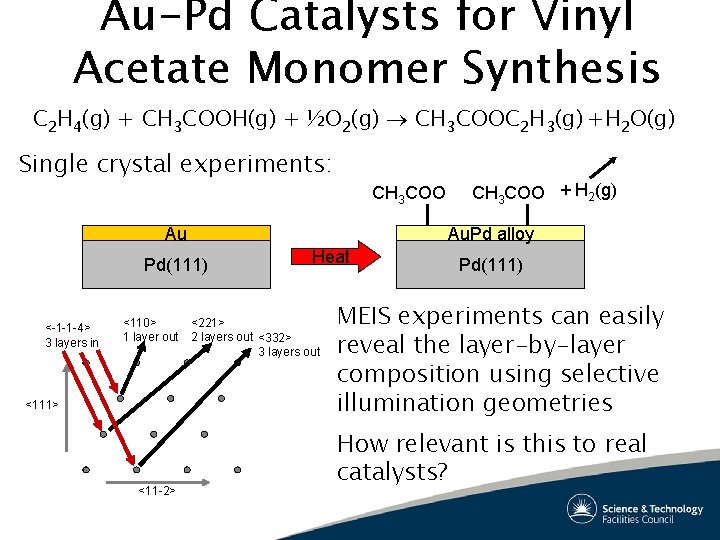
Au-Pd Catalysts for Vinyl Acetate Monomer Synthesis C 2 H 4(g) + CH 3 COOH(g) + ½O 2(g) ® CH 3 COOC 2 H 3(g) +H 2 O(g) Single crystal experiments: CH 3 COO Au Au. Pd alloy Pd(111) <-1 -1 -4> 3 layers in <110> 1 layer out <111> <11 -2> CH 3 COO + H 2(g) Heat <221> 2 layers out <332> 3 layers out Pd(111) MEIS experiments can easily reveal the layer-by-layer composition using selective illumination geometries How relevant is this to real catalysts?
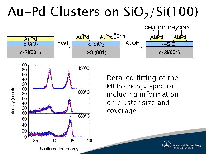
Au-Pd Clusters on Si. O 2/Si(100) CH 3 COO Au. Pd -Si. O 2 c-Si(001) Heat Au. Pd 2 nm Ac. OH -Si. O 2 c-Si(001) Au. Pd -Si. O 2 c-Si(001) Detailed fitting of the MEIS energy spectra including information on cluster size and coverage
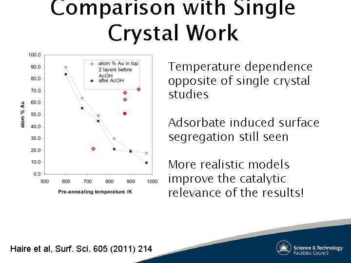
Comparison with Single Crystal Work Temperature dependence opposite of single crystal studies Adsorbate induced surface segregation still seen More realistic models improve the catalytic relevance of the results! Haire et al, Surf. Sci. 605 (2011) 214
Future Research Using MEIS Semiconductor device fabrication • Dielectric layers • Ion implantation • Metalisation Catalysts • Oxide support materials • Bimetallic nanoparticles • Adsorbate induced segregation studies Structural materials (light metal alloys) • Rail, automotive, marine and aerospace applications
Future Research Using MEIS Biomedical applications • Joint replacements, dental implants Photovoltaic materials • Multi-junction solar cells • II-VI quantum dot based solar cells • III-V quantum well LED’s Magnetic materials • Magnetic tunnel junctions • Novel memory materials (MRAM, race track, etc) • Spintronic materials (metal-semiconductor hybrids)
Future Research Using MEIS The ‘Hydrogen economy’ • Photo-catalysts • Hydrogen storage materials • Fuel cells Nanometrology • SIMS Calibration • Elipsometry and other optical techniques Others? ? ?
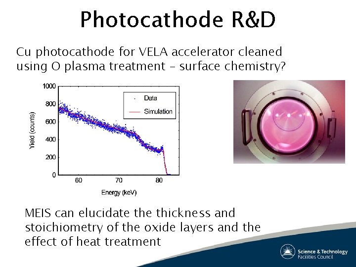
Photocathode R&D Cu photocathode for VELA accelerator cleaned using O plasma treatment – surface chemistry? MEIS can elucidate thickness and stoichiometry of the oxide layers and the effect of heat treatment
Summary MEIS is a fantastic technique for investigating the surface and near-surface region of materials Simultaneous measurement of composition and structure High sensitivity to structural parameters (~2 pm) Virtually monolayer depth resolution
Acknowledgements Daresbury – Paul Bailey, Kevin Connell, Steve Bennett, Graham Bushnell-Wye, Brian Blackwell, Mark Pendleton, Paul Whitfield, Steve Davis, Simon Letts, Vic Pucknell York – Steve Tear, Dave Spence Liverpool – Paul Chalker, Richard Potter, Paul Marshall, Steve Taylor, Anthony Jones Manchester – Peter Skeldon, George Thompson, Sergio Garcia. Vergara Liverpool – Ronan Mc. Grath, Hem-Raj Sharma, Joe Smerdon, Joe Parle, Peter Nugent Warwick – Gavin Bell, Paul Quinn, Neil Wilson, Stuart Hatfield, Chris Mc. Conville, Salim Al-Harthi, Faramaz Gard St Andrews – Chris Baddeley, Andrew Haire, Johan Gustafson, Aofie Trant, Tim Jones