
Mechanistic Study of Di Fluoro Ethylene Carbonate as
Mechanistic Study of Di. Fluoro Ethylene Carbonate as Electrolyte Additive for Rechargeable Na Batteries : A Hybrid MC/MD Simulation Study CREST Workshop Dr. Uppula Purushotham 1
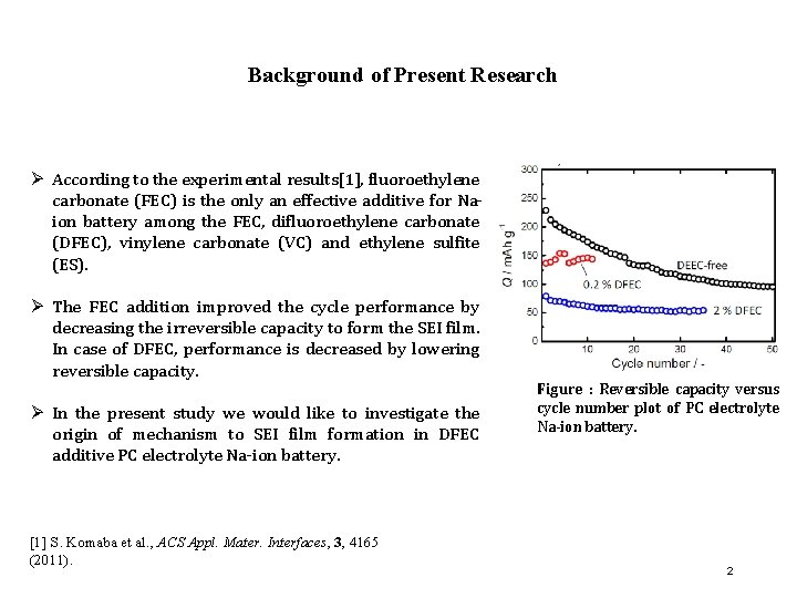
Background of Present Research Ø According to the experimental results[1], fluoroethylene carbonate (FEC) is the only an effective additive for Naion battery among the FEC, difluoroethylene carbonate (DFEC), vinylene carbonate (VC) and ethylene sulfite (ES). Ø The FEC addition improved the cycle performance by decreasing the irreversible capacity to form the SEI film. In case of DFEC, performance is decreased by lowering reversible capacity. Ø In the present study we would like to investigate the origin of mechanism to SEI film formation in DFEC additive PC electrolyte Na-ion battery. [1] S. Komaba et al. , ACS Appl. Mater. Interfaces, 3, 4165 (2011). Figure : Reversible capacity versus cycle number plot of PC electrolyte Na-ion battery. 2
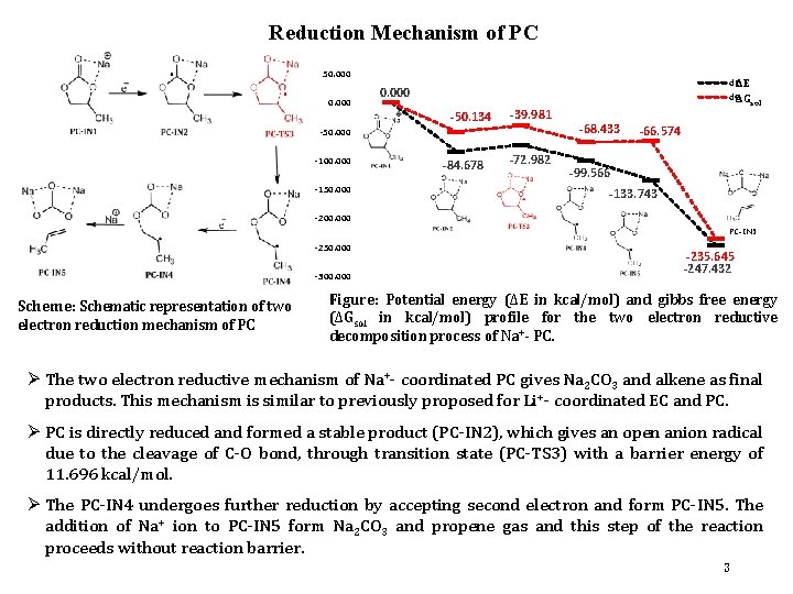
Reduction Mechanism of PC 50. 000 d. EΔΕ d. GΔG 0. 000 -50. 134 -39. 981 -50. 000 -100. 000 -150. 000 -84. 678 -72. 982 sol -68. 433 -66. 574 -99. 566 -133. 743 -200. 000 PC-IN 5 -250. 000 -300. 000 Scheme: Schematic representation of two electron reduction mechanism of PC -235. 645 -247. 432 Figure: Potential energy (ΔΕ in kcal/mol) and gibbs free energy (ΔGsol in kcal/mol) profile for the two electron reductive decomposition process of Na+- PC. Ø The two electron reductive mechanism of Na+- coordinated PC gives Na 2 CO 3 and alkene as final products. This mechanism is similar to previously proposed for Li +- coordinated EC and PC. Ø PC is directly reduced and formed a stable product (PC-IN 2), which gives an open anion radical due to the cleavage of C-O bond, through transition state (PC-TS 3) with a barrier energy of 11. 696 kcal/mol. Ø The PC-IN 4 undergoes further reduction by accepting second electron and form PC-IN 5. The addition of Na+ ion to PC-IN 5 form Na 2 CO 3 and propene gas and this step of the reaction proceeds without reaction barrier. 3
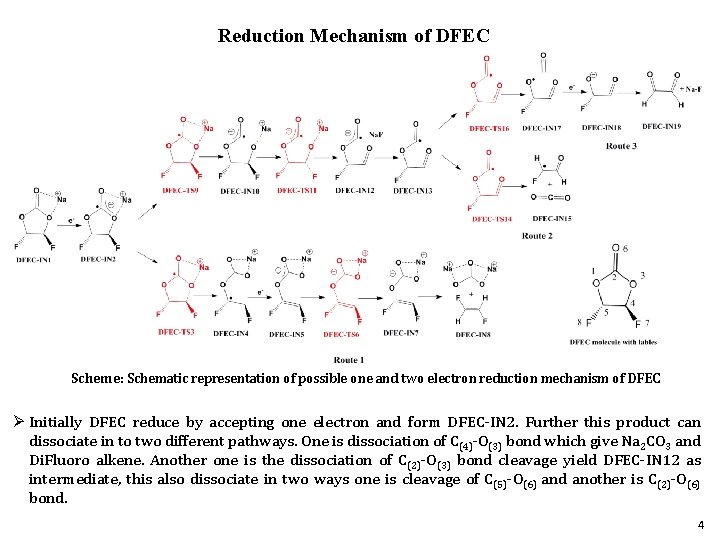
Reduction Mechanism of DFEC Scheme: Schematic representation of possible one and two electron reduction mechanism of DFEC Ø Initially DFEC reduce by accepting one electron and form DFEC-IN 2. Further this product can dissociate in to two different pathways. One is dissociation of C(4)-O(3) bond which give Na 2 CO 3 and Di. Fluoro alkene. Another one is the dissociation of C(2)-O(3) bond cleavage yield DFEC-IN 12 as intermediate, this also dissociate in two ways one is cleavage of C(5)-O(6) and another is C(2)-O(6) bond. 4
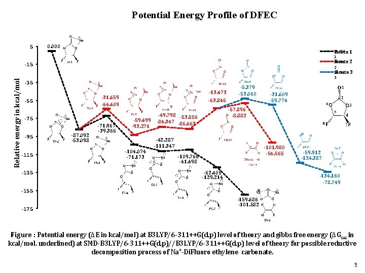
Potential Energy Profile of DFEC 5 0. 000 Series Route 1 1 Route 2 Series Route 3 3 Relative energy in kcal/mol -15 -31. 659 -64. 409 -55 -75 -95 -115 -13. 473 -87. 092 -53. 098 -71. 967 -39. 366 -5. 379 -53. 060 -63. 845 -59. 499 -93. 276 -104. 074 -71. 173 -31. 609 -59. 774 -57. 896 -8. 882 -49. 798 -53. 556 -84. 347 -86. 663 -42. 287 -111. 347 -101. 980 -54. 565 -109. 766 -41. 498 -62. 405 -129. 214 -59. 912 -124. 387 -134. 160 -78. 749 -155 -175 -159. 686 -101. 582 Figure : Potential energy (ΔΕ in kcal/mol) at B 3 LYP/6 -311++G(d, p) level of theory and gibbs free energy (ΔGsol in kcal/mol, underlined) at SMD-B 3 LYP/6 -311++G(d, p)//B 3 LYP/6 -311++G(d, p) level of theory for possible reductive decomposition process of Na+-Di. Fluoro ethylene carbonate. 5

Conclusions ü After one electron reduction of DFEC the C(4)-O(3) bond dissociation occurs via DFEC-TS 3 with 15. 125 kcal/mol activation energy barrier. ü In Route 2 the homolytic fission of C(2)-O(3) bond form a radical anion (DFEC-IN 9) with 22. 683 kcal/mol activation energy barrier. Further dissociation of DFEC-IN 12 via C(5)-O(6) bond proceeds with lower energy than C(2)-O(6) bond dissociation (Route 3). ü In the DFEC mechanism C(4)-O(3) bond cleavage is favorable than C(2)-O(3) bond dissociation, thus Route 1 is favorable with lower reaction barrier. ü The reduced product (PC-IN 2) form an open anion radical due to the cleavage of C-O bond, through transition state (PC-TS 3) with a barrier energy of 11. 696 kcal/mol. Ø Route 1 is favorable with lower reaction barrier, thus we have considered route 1 for MC/MD simulation. DFEC is less reactive than PC with its higher activation energy. Ø We have carried out the MC/MD simulations in two different situations such as one where PC and DFEC are reactive. Second is in the real situation more intact DFEC molecules present in the electrolyte during SEI film formation. Thus, to evaluate the intact DFEC effect we have also carried out the MC/MD simulations where DFEC is non-reactive. 6
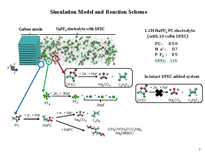
Simulation Model and Reaction Scheme Na. PF 6 electrolyte with DFEC Carbon anode y 1. 1 M Na. PF 6 PC electrolyte (with 10 vol% DFEC) PC: 850 N a+ : 8 7 P F 6 - : 8 5 DFEC: 115 x z + 2 e-, + Na 2 CO 3 DFEC + 2 e-, + 3 Na+ + + e-, + Na+ Na. PC C 2 H 2 F 2 + 2 e-, + Na+ + + DFEC Na 2 CO 3 C 2 H 2 F 2 3 Na. F + Na 2 CO 3 PC + PF 3 PF 6 In intact DFEC added system + C 3 H 6 (CH 3 CHCH 2 OCO 2 Na)2 Na 2 DMBDC 7
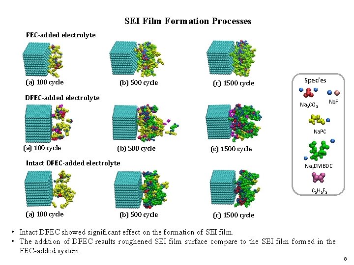
SEI Film Formation Processes FEC-added electrolyte (a) 100 cycle (b) 500 cycle (c) 1500 cycle DFEC-added electrolyte Species Na 2 CO 3 Na. F Na. PC (a) 100 cycle (b) 500 cycle (c) 1500 cycle Intact DFEC-added electrolyte Na 2 DMBDC C 2 H 2 F 2 (a) 100 cycle (b) 500 cycle (c) 1500 cycle • Intact DFEC showed significant effect on the formation of SEI film. • The addition of DFEC results roughened SEI film surface compare to the SEI film formed in the FEC-added system. 8
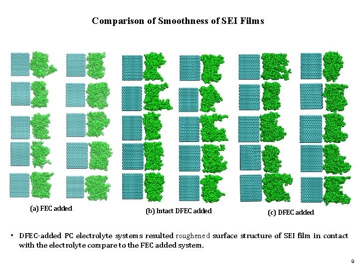
Comparison of Smoothness of SEI Films (a) FEC added (b) Intact DFEC added (c) DFEC added • DFEC-added PC electrolyte systems resulted roughened surface structure of SEI film in contact with the electrolyte compare to the FEC added system. 9
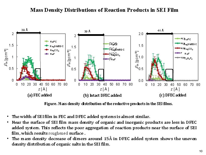
Mass Density Distributions of Reaction Products in SEI Film 39 Å 2 Na. PC Na 2 DMBDC Na 2 CO 3 Na. F 1 Na. PC PC 3 PC 4 Na 2 DMBDC N 2 C Na 2 CO 3 FNa. F 1. 5 [gcm-3] 1. 5 0. 5 1 0 0 10 20 30 40 50 60 70 80 z [Å] (a) FEC added PC 3 Na. PC PC 4 Na DMBDC 1. 5 2 N 2 CNa CO 2 3 F Na. F 1. 0 TDFC 2 H 2 F 2 0. 5 0 41 Å 2. 0 [gcm-3] 39 Å 2 0 10 20 30 40 50 60 70 80 z [Å] (b) Intact DFEC added 0. 0 0 10 20 30 40 50 60 70 80 z [Å] (c) DFEC added Figure. Mass density distribution of the reductive products in the SEI films. • The width of SEI film in FEC and DFEC added systems is almost similar. • Near the surface of SEI film mass density of organic and inorganic products are less in DFEC added system. This reflects the poor aggregation of reaction products near the surface of SEI film, which results roughened surface. • The mass density decrease of dimers around 15Å in DFEC added system shows the uneven density distribution of organic salts in the SEI film. 10
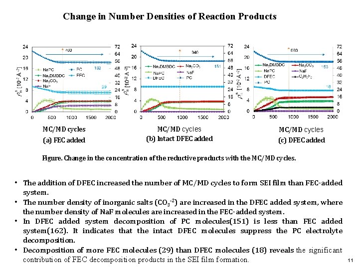
Change in Number Densities of Reaction Products MC/MD cycles (a) FEC added MC/MD cycles (b) Intact DFEC added MC/MD cycles (c) DFEC added Figure. Change in the concentration of the reductive products with the MC/MD cycles. • The addition of DFEC increased the number of MC/MD cycles to form SEI film than FEC-added system. • The number density of inorganic salts (CO 3 -2) are increased in the DFEC added system, where the number density of Na. F molecules are increased in the FEC-added system. • In DFEC added system decomposition of PC molecules(151) is less than FEC added system(162). It indicates that the intact DFEC molecules suppress the PC electrolyte decomposition. • Decomposition of more FEC molecules (29) than DFEC molecules (18) reveals the significant contribution of FEC decomposition products in the SEI film formation. 11
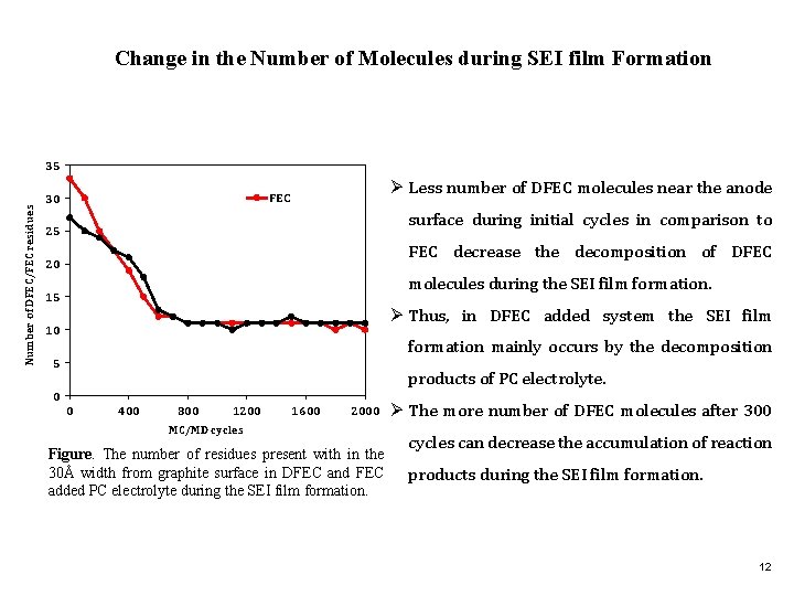
Change in the Number of Molecules during SEI film Formation Number of DFEC/FEC residues 35 Ø Less number of DFEC molecules near the anode FEC 30 surface during initial cycles in comparison to 25 FEC decrease the decomposition of DFEC 20 molecules during the SEI film formation. 15 Ø Thus, in DFEC added system the SEI film 10 formation mainly occurs by the decomposition 5 products of PC electrolyte. 0 0 400 800 1200 1600 2000 MC/MD cycles Figure. The number of residues present with in the 30Å width from graphite surface in DFEC and FEC added PC electrolyte during the SEI film formation. Ø The more number of DFEC molecules after 300 cycles can decrease the accumulation of reaction products during the SEI film formation. 12
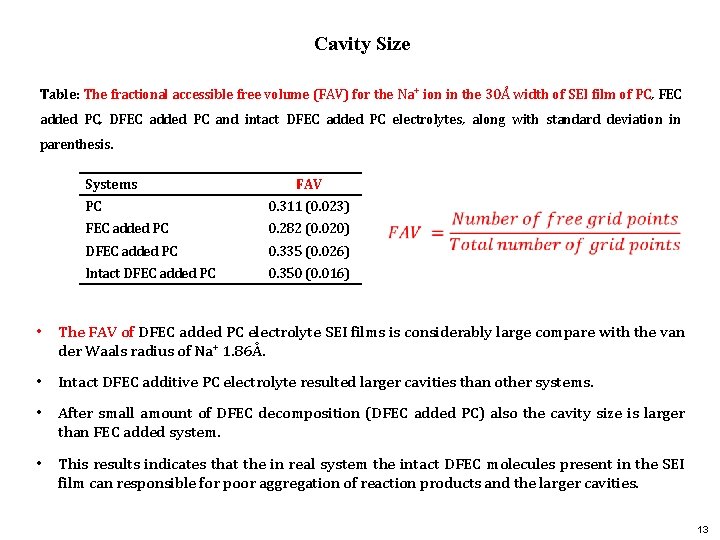
Cavity Size Table: The fractional accessible free volume (FAV) for the Na+ ion in the 30Å width of SEI film of PC, FEC added PC, DFEC added PC and intact DFEC added PC electrolytes, along with standard deviation in parenthesis. Systems FAV PC 0. 311 (0. 023) FEC added PC 0. 282 (0. 020) DFEC added PC 0. 335 (0. 026) Intact DFEC added PC 0. 350 (0. 016) • The FAV of DFEC added PC electrolyte SEI films is considerably large compare with the van der Waals radius of Na+ 1. 86Å. • Intact DFEC additive PC electrolyte resulted larger cavities than other systems. • After small amount of DFEC decomposition (DFEC added PC) also the cavity size is larger than FEC added system. • This results indicates that the in real system the intact DFEC molecules present in the SEI film can responsible for poor aggregation of reaction products and the larger cavities. 13
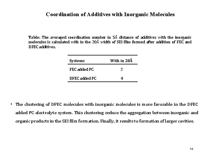
Coordination of Additives with Inorganic Molecules Table: The averaged coordination number in 5Å distance of additives with the inorganic molecules is calculated with in the 20Å width of SEI film formed after addition of FEC and DFEC additives. Systems With in 20Å FEC added PC 2 DFEC added PC 4 • The clustering of DFEC molecules with inorganic molecules is more favorable in the DFEC added PC electrolyte system. This clustering reduce the aggregation between inorganic and organic products in the SEI film formation. Finally, it results to formation of larger cavities. 14
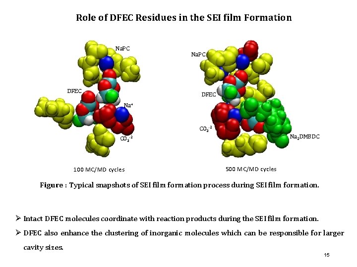
Role of DFEC Residues in the SEI film Formation Na. PC DFEC Na+ CO 3 -2 Na 2 DMBDC CO 3 -2 100 MC/MD cycles 500 MC/MD cycles Figure : Typical snapshots of SEI film formation process during SEI film formation. Ø Intact DFEC molecules coordinate with reaction products during the SEI film formation. Ø DFEC also enhance the clustering of inorganic molecules which can be responsible for larger cavity sizes. 15
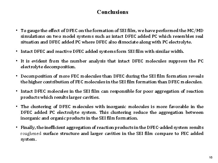
Conclusions • To gauge the effect of DFEC on the formation of SEI film, we have performed the MC/MD simulations on two model systems such as intact DFEC added PC which resembles real situation and DFEC added PC where DFEC also dissociate along with PC electrolyte. • Intact DFEC and reactive DFEC added systems form SEI film with similar width. • It is evident from the number analysis that intact DFEC molecules suppress the PC electrolyte decomposition. • Decomposition of more FEC molecules than DFEC during the SEI film formation reveals the higher contribution of FEC molecules in the SEI film formation than DFEC molecules. • Intact DFEC molecules in the SEI film can responsible for poor aggregation of reaction products which results larger cavities. • The clustering of DFEC molecules with inorganic molecules is more favorable in the DFEC added PC electrolyte system. This clustering reduce the aggregation between inorganic and organic products in the SEI film formation. • Finally, the inefficient aggregation of reaction products in the DFEC-added system results roughened surface structure and larger cavities in the SEI film compare to FEC added system. 16

THANK YOU 17
- Slides: 17