Mechanisms A mechanism is a combination of rigid

Mechanisms A mechanism is a combination of rigid or restraining bodies so shaped and connected that they move upon each other with a definite relative motion. A simple example of this is the slider crank mechanism used in an internal combustion or reciprocating air compressor. Machine A machine is a mechanism or a collection of mechanisms which transmits force from the source of power to the resistance to be overcome, and thus perform a mechanical work.

Kinematic Pairs A mechanism has been defined as a combination so connected that each moves with respect to each other. A clue to the behaviour lies in in the nature of connections, known as kinetic pairs. The degree of freedom of a kinetic pair is given by the number independent coordinates required to completely specify the relative movement. Lower Pairs A pair is said to be a lower pair when the connection between two elements is through the area of contact. Its 6 types are : Revolute which can be expressed by a single coordinate angle 'theta' . Thus a revolute pair has a single degree of freedom.

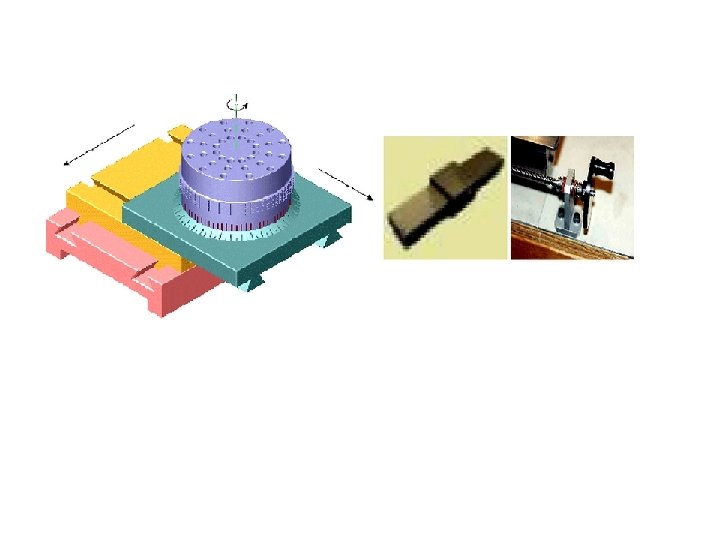
Prismatic Pair A prismatic pair allows only a relative translation between elements 1 and 2, which can be expressed by a single coordinate 'S'. Thus a prismatic pair has a single degree of freedom.
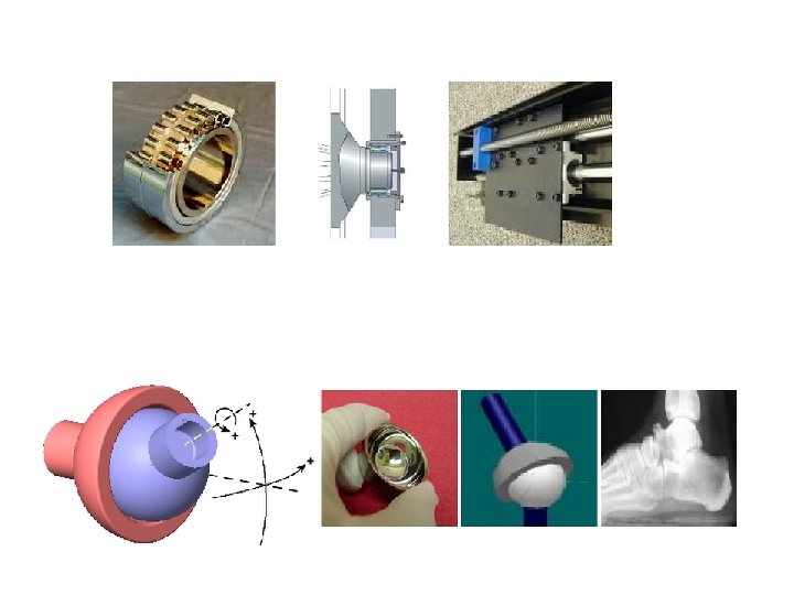

Higher Pairs A higher pair is defined as one in which the connection between two elements has only a point or line of contact. • • A higher pair is defined as one in which the connection between two elements has only a point or line of contact. Two cylinders with unequal radius and with axis parallel make contact along a line. A point contact takes place when spheres rest on plane or curved surfaces (ball bearings) or between teeth of a skew-helical gears. Wrapping Pairs comprise belts, chains, and other such devices.

Mechanisms Plane Mechanisms If all the points of a mechanism move in parallel planes, then it is defined as a plane mechanism. Spatial Mechanisms If all the points do not move in parallel planes then it is called spatial mechanism.


To define a mechanism we define the basic elements as follows : Link A material body which is common to two or more kinematic pairs is called a link. Thus a link should have the following two characteristics: 1. It should have relative motion, and 2. It must be a resistant body. Types of Links In order to transmit motion, the driver and the follower may be connected by the following three types of links : 1. Rigid link. A rigid link is one which does not undergo any deformation while transmitting motion. connecting rod, crank etc. of a reciprocating steam engine is not appreciable, they can be considered as rigid links. 2. Flexible link. A flexible link is one which is partly deformed in a manner not to affect the transmission of motion. belts, ropes, chains and wires are flexible links and transmit tensile forces only. 3. Fluid link. A fluid link is one which is formed by having a fluid in a receptacle and the motion is transmitted through the fluid by pressure or compression only, the case of hydraulic presses, jacks and brakes.

Types of Joints 1. Binary joint. When two links are joined at the same connection, the joint is known as binary joint. 2. Ternary joint. When three links are joined at the same connection, the joint is known as ternary joint. 3. Quaternary joint. When four links are joined at the same connection, the joint is called a quaternary joint.

Kinematic Chain A kinematic chain is a series of links connected by kinematic pairs. Kinematic Chain closed chain • open chain The chain is said to be closed chain if every ink is connected to at least two other links, otherwise it is called an open chain. • A link which is connected to only one other link is known as singular link. • If it is connected to two other links, it is called binary link. • If it is connected to three other links, it is called ternary link, and so on. • A chain which consists of only binary links is called simple chain.

Simple closed chain needs at least 3 links 2 3 1 It is an assemblage of a number of resistant bodies having no relative motion between them and meant for carrying loads having straining action. A railway bridge, a roof truss, machine frames etc. , are the examples of a structure. Difference Between a Machine and a Structure 1. The parts of a machine move relative to one another, whereas the members of a structure do not move relative to one another. 2. A machine transforms the available energy into some useful work, whereas in a structure no energy is transformed into useful work. 3. The links of a machine may transmit both power and motion, while the members of a structure transmit forces only.

Number of Degrees of Freedom for Plane Mechanisms If all the points of a mechanism move in parallel planes, then it is defined as a plane mechanism. It is possible to determine the number of degrees of freedom of a mechanism directly from the number of links and the number and types of joints which it includes.

Four link planner mechanisms: 1. Simplest of all mechanisms 2. Large variety of motions is possible 3. Four lower pairs are required 4. Basically two types of pairs are used: 1) revolute pair (R) 5. Combinations: 1) RRRR 2) RRRP 3) RRPP 4)RPRP 2) prismatic pair (P)

KINEMATIC INVERSION • The process of fixing different links of a kinematic chain one at a time to produce distinct mechanisms is called kinematic inversion. Here the relative motions of the links of the mechanisms remain unchanged. • First, let us consider the simplest kinematic chainlike. , a chain consisting of four binary links and four revolute pairs. The four different mechanisms can be obtained by four different inversions of the chain. INVERSIONS OF RRRR

INVERSIONS OF RRRP SLIDER CRANK QUICK RETURN Oscillatory cylinder


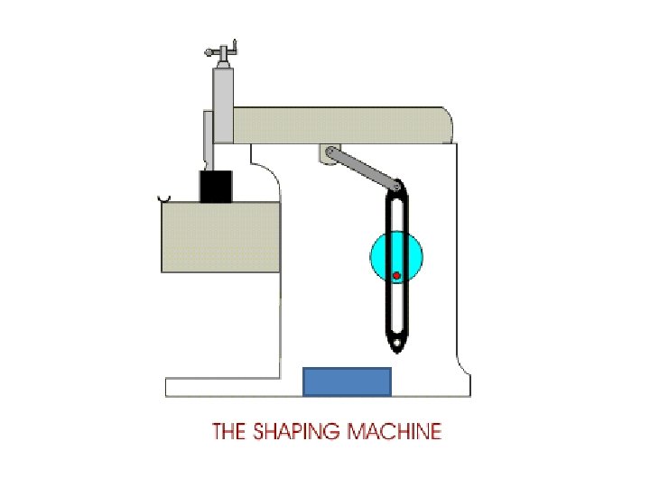
Crank and slotted lever quick return motion mechanism In the extreme positions, AP 1 and AP 2 are tangential to the circle and the cutting tool is at the end of the stroke. The forward or cutting stroke occurs when the crank rotates from the position CB 1 to CB 2 (or through an angle β) in the clockwise direction. The return stroke occurs when the crank rotates from the position CB 2 to CB 1 (or through angle α) in the clockwise direction. Since the crank has uniform angular speed, Therefore,

Whitworth quick return motion mechanism 1. When the driving crank CA moves from the position CA 1 to CA 2 (or the link DP from the position DP 1 to DP 2) through an angle α in the clockwise direction, the tool moves from the left hand end of its stroke to the right hand end through a distance 2 PD. 2. The time taken during the left to right movement of the ram (i. e. during forward or cutting stroke) will be equal to the time taken by the driving crank to move from CA 1 to CA 2. Similarly, the time taken during the right to left movement of the ram (or during the idle or return stroke) will be equal to the time taken by the driving crank to move from CA 2 to CA 1 3. Since the crank link CA rotates at uniform angular velocity therefore time taken during the cutting stroke (or forward stroke) is more than the time taken during the return stroke.

Double Slider Crank Chain A kinematic chain which consists of two turning pairs and two sliding pairs is known as double slider crank chain, Inversions of Double Slider Crank Chain 1. Elliptical trammels. It is an instrument used for drawing ellipses. This inversion is obtained by fixing the slotted plate (link 4), as shown in Fig.

Scotch yoke mechanism. This mechanism is used for converting rotary motion into a reciprocating motion. Oldham’s coupling. An oldham's coupling is used for connecting two parallel shafts whose axes are at a small distance apart. The shafts are coupled in such a way that if one shaft rotates, the other shaft also rotates at the same speed. This inversion is obtained by fixing the link 2, as shown in Fig.

Displacement, Velocity And Acceleration Analysis

The objective of kinematic analysis is to determine the kinematic quantities such as displacements, velocities, and accelerations of the elements of a mechanism when the input motion is given. It establishes the relationship between the motions of various components of the linkage. When the kinematic dimensions and the configurations of the input link of a mechanism are prescribed, the configurations of all the other links are determined by displacement analysis. Analysis of can performed in two ways: 1. Graphical Method: In a graphical method of displacement analysis, the mechanism is drawn to a convenient scale and the desired unknown quantities are determined through suitable geometrical constructions and calculations. The mechanism is drawn to a convenient scale and the desired unknown quantities are determined through suitable geometrical constructions and calculations. 1. The configurations of a rigid body in plane motion are completely defined by the locations of any two points on it. 2. Two intersecting circles have two points of intersection and one has to be careful, when necessary, to choose the correct point for the purpose in hand. 3. The use of tracing paper, as an overlay, is very convenient and very often provides an unambiguous and quick solution. 4. The graphical method fails if no closed loop with four links exists in the mechanism.

2. Analytical Method Consider a four bar mechanism ABCD, as shown in Fig. in which AB = a (input link), BC = b (coupler), CD = c (output link) DA = d (fixed link) 1. Displacement analysis For equilibrium of the mechanism, the sum of the components along X-axis and along Y-axis must be equal to zero. sum of the components along X-axis :

sum of the components along Y-axis To remove ‘beta’ term

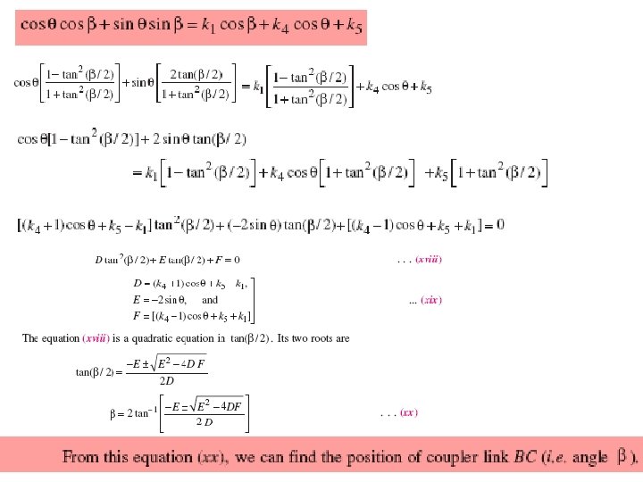
Since it is very difficult to determine the value of for the given value of Ф , from equation (vii), therefore it is necessary to simplify this equation. we know that
, we can find the position of output link CD if")
From this equation (x), we can find the position of output link CD if the length of the links (i. e. a, b, c and d) and position of the input link AB is known. If the relation between the position of input link AB and the position of coupler link BC is required, then eliminate angle from the equations (i) and (iii).
 and (xiv),")
Adding equations (xii) and (xiv),

2. Velocity analysis
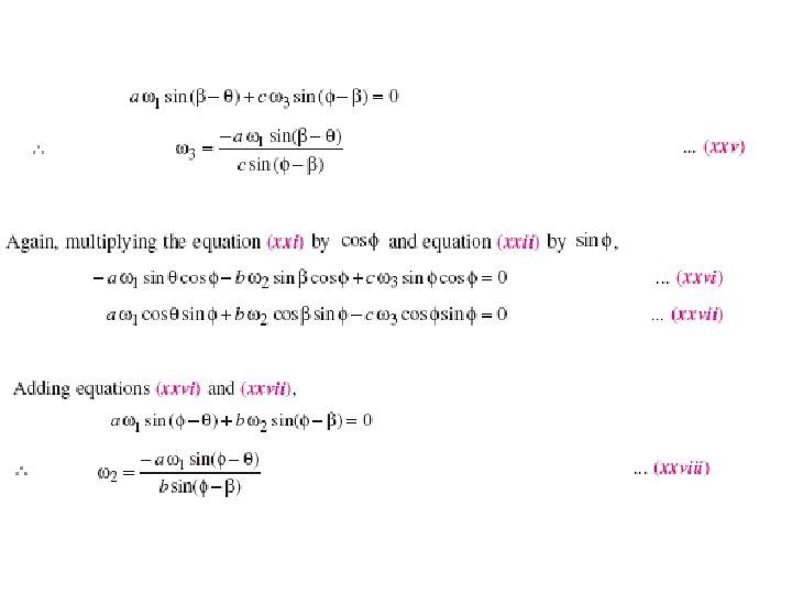
 with respect to time, Again, differentiating equation (xxii)")
3. Acceleration analysis Differentiating equation (xxi) with respect to time, Again, differentiating equation (xxii) with respect to time,
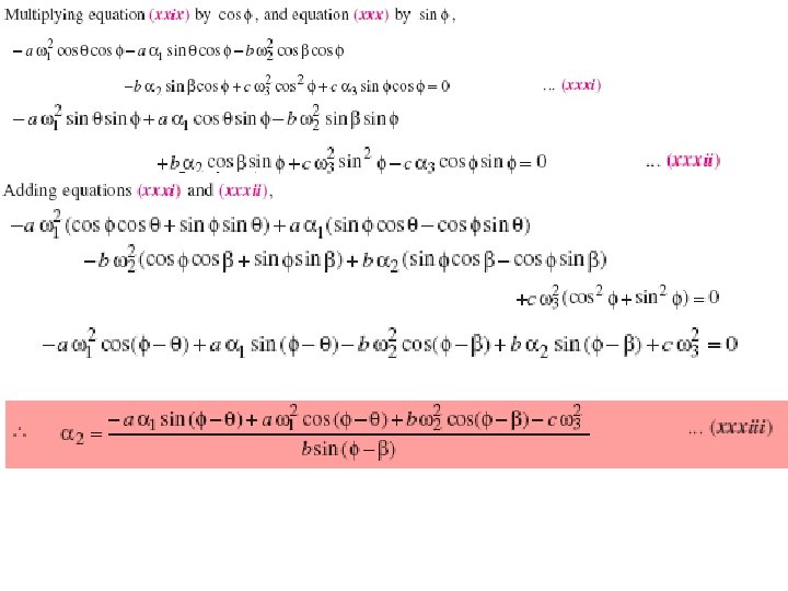

Determination of α 3

Straight Line Motion Mechanisms

Straight Line Mechanisms • One of the most common forms of the constraint mechanisms is that it permits only relative motion of an oscillatory nature along a straight line. The mechanisms used for this purpose are called straight line mechanisms. • These mechanisms are of the following two types: 1. in which only turning pairs are used, and 2. in which one sliding pair is used. • These two types of mechanisms may produce exact straight line motion or approximate straight line motion.

Approximate Straight Line Motion Mechanisms • The approximate straight line motion mechanisms are the modifications of the four-bar chain 1. Watt’s mechanism. It is a crossed four bar chain mechanism and was used by Watt for his early steam engines to guide the piston rod in a cylinder to have an approximate straight line motion

2. Modified Scott-Russel mechanism. in this case AP is not equal to AQ and the points P and Q are constrained to move in the horizontal and vertical directions. A little consideration will show that it forms an elliptical trammel, so that any point A on PQ traces an ellipse with semimajor axis AQ and semi-minor axis AP If the point A moves in a circle, then for point Q to move along an approximate straight line, the length OA must be equal (AP)2 / AQ. This is limited to only small displacement of P

3. Grasshopper mechanism. This mechanism is a modification of modified Scott-Russel’s mechanism with the difference that the point P does not slide along a straight line, but moves in a circular arc with centre O. It is a four bar mechanism and all the pairs are turning pairs as shown in Fig. In this mechanism, the centres O and O 1 are fixed. The link OA oscillates about O through an angle AOA 1 which causes the pin P to move along a circular arc with O 1 as centre and O 1 P as radius. For small angular displacements of OP on each side of the horizontal, the point Q on the extension of the link PA traces out an approximately a straight path QQ′, if the lengths are such that OA= (AP)2 / AQ. Note: The Grasshopper mechanism was used in early days as an engine mechanism which gave long stroke with a very short crank.

4. Tchebicheff’s mechanism. 1. It is a four bar mechanism in which the crossed links OA and O 1 B are of equal length, as shown in Fig. 2. The point P, which is the mid-point of AB traces out an approximately straight line parallel to OO 1. 3. The proportions of the links are, usually, such that point P is exactly above O or O 1 in the extreme positions of the mechanism i. e. when BA lies along OA or when BA lies along BO 1. 4. It may be noted that the point P will lie on a straight line parallel to OO 1, in the two extreme positions and in the mid position, if the lengths of the links are in proportions AB : OO 1 : OA = 1 : 2. 5.

5. Roberts mechanism. 1. It is also a four bar chain mechanism, which, in its mean position, has the form of a trapezium. 2. The links OA and O 1 B are of equal length and OO 1 is fixed. 3. A bar PQ is rigidly attached to the link AB at its middle point P. 4. A little consideration will show that if the mechanism is displaced as shown by the dotted lines in Fig. the point Q will trace out an approximately straight line.

Condition for Exact Straight Line Motion Mechanisms • The principle adopted for a mathematically correct or exact straight line motion is described in Fig. • Let O be a point on the circumference of a circle of diameter OP. Let OA be any chord and B is a point on OA produced, such that OA × OB = constant • Then the locus of a point B will be a straight line perpendicular to the diameter OP.

Proof: • Draw BQ perpendicular to OP produced. Join AP. The triangles OAP and OBQ are similar. • But OP is constant as it is the diameter of a circle, therefore, if OA × OB is constant, then OQ will be constant. Hence the point B moves along the straight path BQ which is perpendicular to OP. A B Base O P O Base Q

Exact Straight Line Motion Mechanisms • • Peaucellier exact straight line motion mechanism: It consists of a fixed link OO 1 and the other straight links O 1 A, OC, OD, AD, DB, BC and CA are connected by turning pairs at their intersections, as shown in Fig. The pin at A is constrained to move along the circumference of a circle with the fixed diameter OP, by means of the link O 1 A. In Fig. , AC = CB = BD = DA ; OC = OD ; and OO 1=O 1 A It may be proved that the product OA × OB remains constant, when the link O 1 A rotates. Join CD to bisect AB at R. Now from right angled triangles ORC and BRC, we have Since OC and BC are of constant length, therefore the product OB × OA remains constant. Hence the point B traces a straight path perpendicular to the diameter OP.

2. Hart’s mechanism. 1. This mechanism requires only six links as compared with the eight links required by the Peaucellier mechanism. 2. It consists of a fixed link OO 1 and other straight links O 1 A, FC, CD, DE and EF are connected by turning pairs at their points of intersection, as shown in Fig. 3. The links FC and DE are equal in length and the lengths of the links CD and EF are also equal. 4. The points O, A and B divide the links FC, CD and EF in the same ratio. A little consideration will show that BOCE is a trapezium and OA and OB are respectively parallel to * FD and CE. Hence OAB is a straight line. It may be proved now that the product OA × OB is constant.

It therefore follows that if the mechanism is pivoted about O as a fixed point and the point A is constrained to move on a circle with centre O 1, then the point B will trace a straight line perpendicular to the diameter OP produced

3. Exact Straight Line Motion Consisting of One Sliding Pair-Scott Russell’s Mechanism It consists of a fixed member and moving member P of a sliding pair as shown in Fig. The straight link PA Q is connected by turning pairs to the link OA and the link P. The link OA rotates about O. A little consideration will show that the mechanism OAP is same as that of the reciprocating engine mechanism in which OA is the crank and PA is the connecting rod. In this mechanism, the straight line motion is not generated but it is merely copied.

Intermittent Motion Mechanism • Intermittent motion means that the motion is not continuous, but it ceases after definite intervals. • Intermittent rotary motion is required generally in machine tools where work table, hexagonal turret, and spindle are to be indexed.

Geneva Mechanism • Figure shows a Geneva wheel mechanism which consists of a driving wheel 1. • It rotates continuously, and carries a pin P that engages in a slot in die driven member 2. • The follower or driven member 2 is turned 1/4 th of a revolution for each revolution of plate 1.

• • • Ratchet and Pawl Mechanism Figure shows the details of a pawl and ratchet mechanism. This mechanism is used to produce intermittent circular motion from an oscillating or reciprocating member. Wheel 4 is given intermittent circular motion by means of arm 2 and driving pawl 3. A second pawl 5 prevents 4 from turning backward when 2 is rotated clockwise in preparation for another stroke. The line of action PN of the driving pawl and tooth must pass between centres O and A in order to have pawl 3 remain in contact with the tooth.

Toggle Mechanism • Toggle mechanisms are used, where large resistances are to be overcome through short distances. Here, effort applied will be small but acts over large distance. • In the mechanism shown in fig, 2 is the input link, to which, power is supplied and 6 is the output link, which has to overcome external resistance. Links 4 and 5 are of equal length. • Considering the equilibrium condition of slider 6, • For small angles of α, F (effort) is much smaller than P(resistance). • This mechanism is used in rock crushers, presses, riveting machines etc.

Ratchet

Pantograph • • Pantographs are used for reducing or enlarging drawings and maps. They are also used for guiding cutting tools or torches to fabricate complicated shapes. In the mechanism shown in fig. path traced by point A will be magnified by point E to scale, as discussed below. In the mechanism shown, AB = CD; AD =BC and OAE lie on a straight line. When point A moves to A’ , E moves to E’ and OA’E’ also lies on a straight line.

Steering Gear Mechanism • The steering gear mechanism is used for changing the direction of two or more of the wheel axles with reference to the chassis, so as to move the automobile in any desired path. • Usually the two back wheels have a common axis, which is fixed in direction with reference to the chassis and the steering is done by means of the front wheels. • In automobiles, the front wheels are placed over the front axles, which are pivoted at the points A and B, as shown in Fig. These points are fixed to the chassis. • When the vehicle takes a turn, the front wheels along with the respective axles turn about the respective pivoted points. • The back wheels remain straight and do not turn. Therefore, the steering is done by means of front wheels only.

Condition for perfect steering • In order to avoid skidding (i. e. slipping of the wheels sideways), the two front wheels must turn about the same instantaneous centre I which lies on the axis of the back wheels. • If the instantaneous centre of the two front wheels do not coincide with the instantaneous centre of the back wheels, the skidding on the front or back wheels will definitely take place, which will cause more wear and tear of the tyres. • Thus, the condition for correct steering is that all the four wheels must turn about the same instantaneous centre. • The axis of the inner wheel makes a larger turning angle than the angle subtended by the axis of outer wheel.

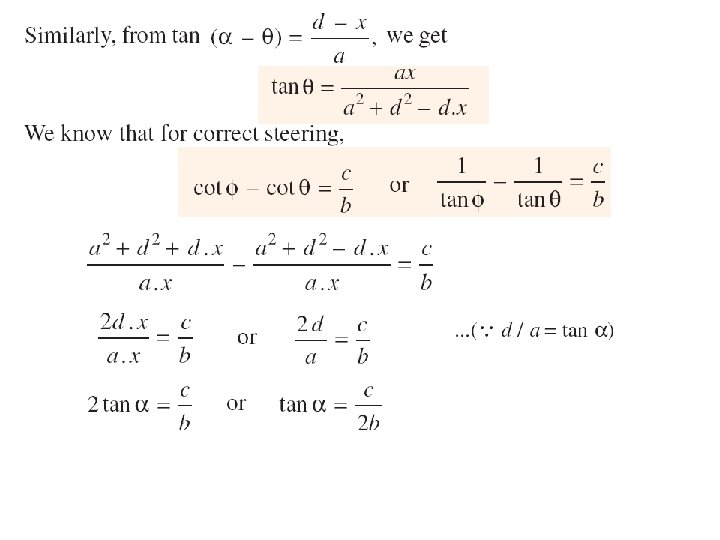
• Condition for perfect steering This is the fundamental equation for correct steering. If this condition is satisfied, there will be no skidding of the wheels, when the vehicle takes a turn.

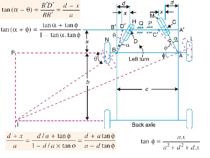
Davis Steering Gear The Davis steering gear is shown in Fig. The slotted links AM and BH are attached to the front wheel axle, which turn on pivots A and B respectively. The rod CD is constrained to move in the direction of its length, by the sliding members at P and Q. The steering is affected by moving CD to the right or left of its normal position. C D shows the position of CD for turning to the left. Let a = Vertical distance between AB and CD, b = Wheel base, d = Horizontal distance between AC and BD, c = Distance between the pivots A and B of the front axle. x = Distance moved by AC to AC = CC = DD, and = Angle of inclination of the links AC and BD, to the vertical.

ACKERMANN STEERING GEAR MECHANISM • In Ackerman steering gear, the mechanism ABCD is a four bar crank chain, as shown in Fig. • The shorter links BC and AD are of equal length and are connected by hinge joints with front wheel axles. The longer links AB and CD are of unequal length. The following are the only three positions for correct steering. 1. When the vehicle moves along a straight path, the longer links AB and CD are parallel and the shorter links BC and AD are equally inclined to the longitudinal axis of the vehicle, as shown by firm lines in Fig. . 2. When the vehicle is steering to the left, the position of the gear is shown by dotted lines in Fig. In this position, the lines of the front wheel axle intersect on the back wheel axle at I, for correct steering. 3. When the vehicle is steering to the right, the similar position may be obtained.

Hook’s Joint 62

Introduction • This joint was first invented by Da Vinci, an English physicist and mathematician Robert Hooke's (1635 -1703) name is associated with it since he put it to use for connecting two non-parallel and intersecting shafts. • It is commonly knows as 'Universal Joint'. 63

Introduction • It is used for transmitting power from engine gear box to the rear axle of the automobile. • It is also used in knee joint of a milling machine. • The angle between the driving and driven shafts may be constant but usually it varies while the vehicle moves on an uneven surface. 64

Introduction 65

Introduction 66

Introduction • One of the disadvantages of this joint is that the velocity ratio is not constant, because the driving shaft rotates at a uniform angular speed but the driven shaft rotates at a varying angular speed. • Because of variation in the output speed (driven), single Hooke's joint is not recommended for high speeds as it may cause excessive vibrations in the system. • To have constant velocity ratio, double Hooke's joints are used. 67

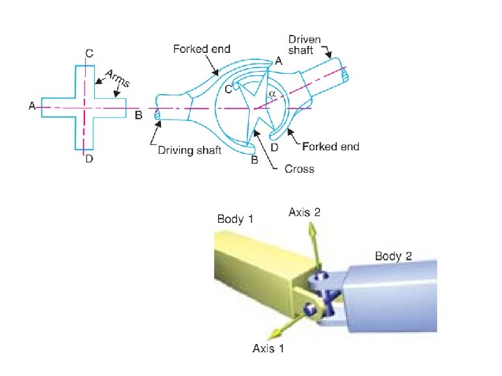
Construction • The universal joint consists of two shafts '1' and '2' known as the driving and the driven shafts respectively. • These shafts rotate in fixed bearings. • Each shaft carries a semicircular fork at its end. • The angle between the shafts is assumed as 'α'. • The ends of the forks are connected by a center piece, which is in the shape of a cross, sphere or square. • This cross has four arms which are at right angles to each other. • The fork ends of the driving shaft T are 'A' and 'B’ and that of driven shaft '2' are 'C' and 'D’. 68
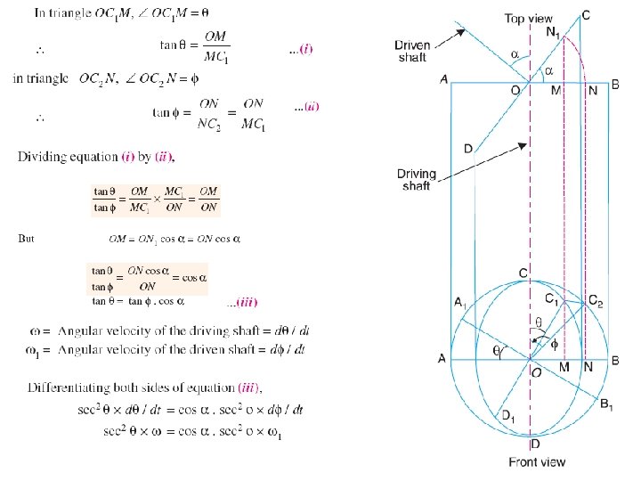
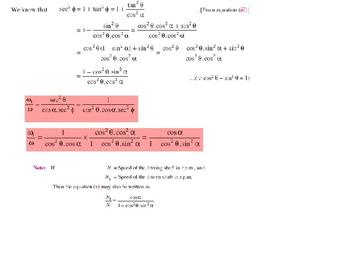

Maximum and Minimum speeds of the driven shaft. 72

The speed variations of the driven shaft are shown on the polar diagram as shown 73

Condition for Equal speeds. This condition is satisfied at four points 5, 6, 7 and 8 74

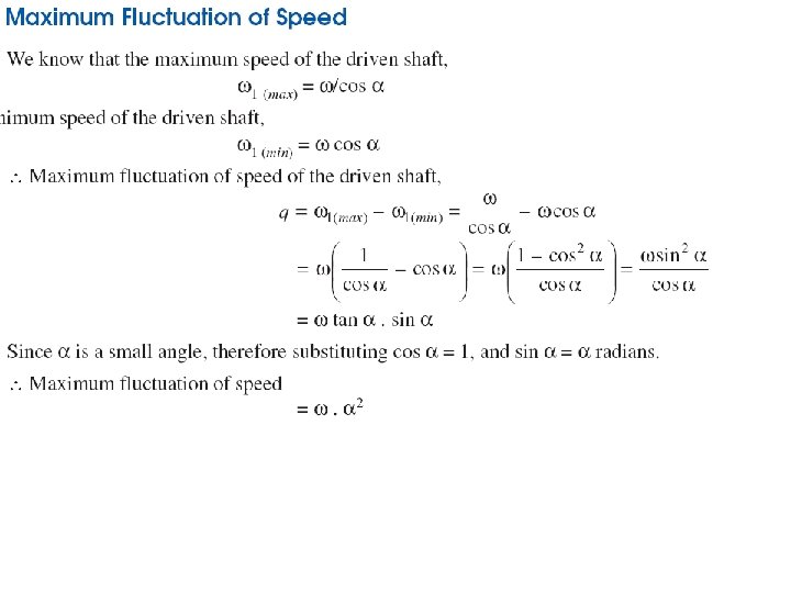
Maximum Variation of speed. 75

Angular Acceleration of the Driven Shaft. The maximum or minimum value of the angular acceleration can be obtained by differentiating the above equation w. r. t. 'Θ' and putting it equal to zero. The approximate final result can be written as: The angular acceleration of the driven shaft is a maximum, when `Θ 'is about 45°, 135° etc. that is when the arms of the cross are inclined at 45° to the plane containing the axes of the two shafts. 76

Double Hooke’s Joint 1. We have seen in the previous articles, that the velocity of the driven shaft is not constant, but varies from maximum to minimum values. 2. In order to have a constant velocity ratio of the driving and driven shafts, an intermediate shaft with a Hooke’s joint at each end as shown in Fig. is used. 3. This type of joint is known as double Hooke’s joint.

Velocity Analysis

Thus, this combined motion of rotation and translation of the link AB may be assumed to be a motion of pure rotation about some centre I, known as the instantaneous centre of rotation (also called centro or virtual centre). Methods for Determining the Velocity of a Point on a Link The following two methods are important from the subject point of view. 1. Instantaneous centre method, 2. Relative velocity method. • The instantaneous centre method is convenient and easy to apply in simple mechanisms, • whereas the relative velocity method may be used to any configuration diagram.

Velocity of a Point on a Link by Instantaneous Centre Method

Number of Instantaneous Centres in a Mechanism Types of Instantaneous Centres The instantaneous centres for a mechanism are of the following three types : 1. Fixed instantaneous centres, 2. Permanent instantaneous centres, 3. Neither fixed nor permanent instantaneous centres. The first two types i. e. fixed and permanent instantaneous centres are together known as primary instantaneous centres and the third type is known as secondary instantaneous centres.

Location of Instantaneous Centres 1. When the two links are connected by a pin joint (or pivot joint), the instantaneous centre lies on the centre of the pin as shown in Fig. 2. When the two links have a pure rolling contact (i. e. link 2 rolls without slipping upon the fixed link 1 which may be straight or curved), the instantaneous centre lies on their point of contact as shown in 3. When the link 2 (slider) moves on fixed link 1 having straight surface as shown in Fig. (c), the instantaneous centre lies at infinity and each point on the slider have the same velocity. 4. When the link 2 (slider) moves on fixed link 1 having curved surface as shown in Fig. (d), the instantaneous centre lies on the centre of curvature of the curvilinear path in the configuration at that instant. 5. When the link 2 (slider) moves on fixed link 1 having constant radius of curvature as shown in Fig. (e), the instantaneous centre lies at the centre of curvature i. e. the centre of the circle, for all configuration of the links.
 Theorem The Aronhold Kennedy’s theorem states that")
Aronhold Kennedy (or Three Centres in Line) Theorem The Aronhold Kennedy’s theorem states that if three bodies move relatively to each other, they have three instantaneous centres and lie on a straight line. let us consider that the instantaneous centre Ibc lies outside the line joining Iab and Iac as shown in Fig. The point Ibc belongs to both the links B and C. Let us consider the point Ibc on the link B. Its velocity v. BC must be perpendicular to the line joining Iab and Ibc. Now consider the point Ibc on the link C. Its velocity v. BC must be perpendicular to the line joining Iac and Ibc.

Example: Locate all the instantaneous centres of the slider crank mechanism as shown in Fig. The lengths of crank OB and connecting rod AB are 100 mm and 400 mm respectively. If the crank rotates clockwise with an angular velocity of 10 rad/s, find: 1. Velocity of the slider A, and 2. Angular velocity of the connecting rod AB.
- Slides: 85