MECHANISM 1 KINEMATIC LINK KINEMATIC PAIR KINEMATIC CHAIN


![Inversion of Four Bar Chain Beam Engine [Crank & Leaver Mechanism] ØFour Bar Mechanism](https://slidetodoc.com/presentation_image_h2/11665ecb6c1e93db2b7b31dfd8b1e674/image-14.jpg "Inversion of Four Bar Chain Beam Engine [Crank & Leaver Mechanism] ØFour Bar Mechanism")
![Coupling Rod of locomotive [Double Crank Mechanism] Link AB and CD are of equal](https://slidetodoc.com/presentation_image_h2/11665ecb6c1e93db2b7b31dfd8b1e674/image-16.jpg "Coupling Rod of locomotive [Double Crank Mechanism] Link AB and CD are of equal")
")


- Slides: 23
MECHANISM 1
�KINEMATIC LINK �KINEMATIC PAIR �KINEMATIC CHAIN �MECHANISM
KINEMATIC LINK �A resistant body, which is a part of the machine and has a motion relative to other connected parts is known as kinematic link. Prof. Pritam D. Gole 5
KINEMATIC PAIR � Kinematic link which are connected together in such a way that relative motion is in a definite directions 6
Prof. Pritam D. Gole 7
Kinematic Chain When the kinematic pairs are connected in such manner that, the last link is joined to the first link transmit completely or successfully constrained then it is called as Kinematic Chain.
�Mechanism � When one of the links of a kinematic chain is fixed, the chain is known as mechanism. It may be used for transmitting or transforming motion e. g. engine indicators, typewriter etc. � A mechanism with four links is known as simple mechanism, and the mechanism with more than four links is known as compound mechanism. engine indicators, typewriter etc.
�Inversion of Mechanism � When one of links is fixed in a kinematic chain, it is called a mechanism. So we can obtain as many mechanisms as the number of links in a kinematic chain by fixing, in turn, different links in a kinematic chain. This method of obtaining different mechanisms by fixing different links in a kinematic chain, is known as inversion of the mechanism. �Machine � It is a combination of resistant bodies, with definite (constrained) relative motions, which is used for transmitting or transforming available energy so as to do some particular kind of work
Sr. No. Mechanism Machine 1 When one of the links of a kinematic chain is fixed, the chain is known as mechanism. It may be used for transmitting or transforming motion It is a combination of resistant bodies, with definite (constrained) relative motions, which is used for transmitting or transforming available energy so as to do some particular kind of work 2 The primary function of mechanism is to transmit or transfer the motion The primary function of machine is to transmit or transfer the energy 3 Every mechanism is not necessarily a machine Every machine is either a mechanism or a combination of more than one mechanisms 4 Examples of mechanism are: clock, type-writer, lock, P-V diagram indicator of engine, etc Example of machine are : I. C. engine, shaping machine, hand Pump, etc
Inversion of Four bar Chain � � � Four bar links which forms four turning pair. Length of four links may be different. The link connected to crank and Rocker or lever is called coupler. The shorter link will make a complete revolution relative to the other three link i. e crank or driver. The fixed link of the mechanism is called frame i. e ground.
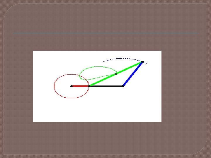
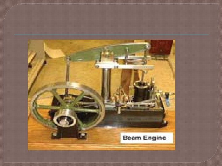
Inversion of Four Bar Chain Beam Engine [Crank & Leaver Mechanism] ØFour Bar Mechanism ØWhen crank rotates about A, � lever oscillates about point D, The end E is connected to piston rod which reciprocates due to rotation of crank � Convert rotary into reciprocating motion �
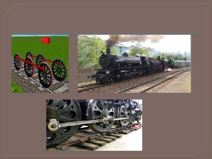
Coupling Rod of locomotive [Double Crank Mechanism] Link AB and CD are of equal lengths and act as a crank are connected to wheel. � AB : is Coupler � AD: is fixed and to maintain a constant center to centre dist. Between them. � Transmit rotary motion from one wheel to another. �
3. Ackermann steering gear mechanism (Double lever Mechanism)
Convert rotary motion into reciprocating motion
Single Slider Crank Chain � A single slider crank chain is a modification of the basic four bar chain. � It consist of one sliding pair and three turning pairs. It is, usually, found in reciprocating steam engine mechanism. � This type of mechanism converts rotary motion into reciprocating motion and vice versa. In a single slider crank chain, as shown in Fig. , the links 1 and 2, links 2 and 3, and links 3 and 4 form three turning pairs while the links 4 and 1 form a sliding pair. � The link 1 corresponds to the frame of the engine, which is fixed. The link 2 corresponds to the crank ; link 3 corresponds to the connecting rod and link 4 corresponds to piston. As the crank rotates, the cross-head reciprocates in the guides and thus the piston reciprocates in the cylinder. links 4 links 3 links 1 links 2
Prof. Pritam D. Gole 21
Ø Geneva Mechanism is used to converting the constant rotary motion into intermittent indexing motion. Ø Used for indexing of a work table on the machine tool.
Ø Oscillating Motion of the driving arm is converted into intermittent rotor motion of the driven ratchet. Ø Used for counting devices, clockworks, lifting jacks etc.