Mechanical Advantage Explore mechanical advantage and gear ratios


.")


- Slides: 53
Mechanical Advantage Explore mechanical advantage and gear ratios with the Gear Box!
Discover new hands-on builds and programming opportunities to further your understanding of a subject matter.
The Completed Look of the Build V 5 Gear Box Explore mechanical advantage and gear ratios!
Parts Needed Can be built with: VEX V 5 Classroom Super Kit
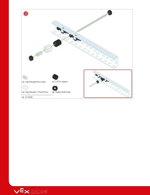
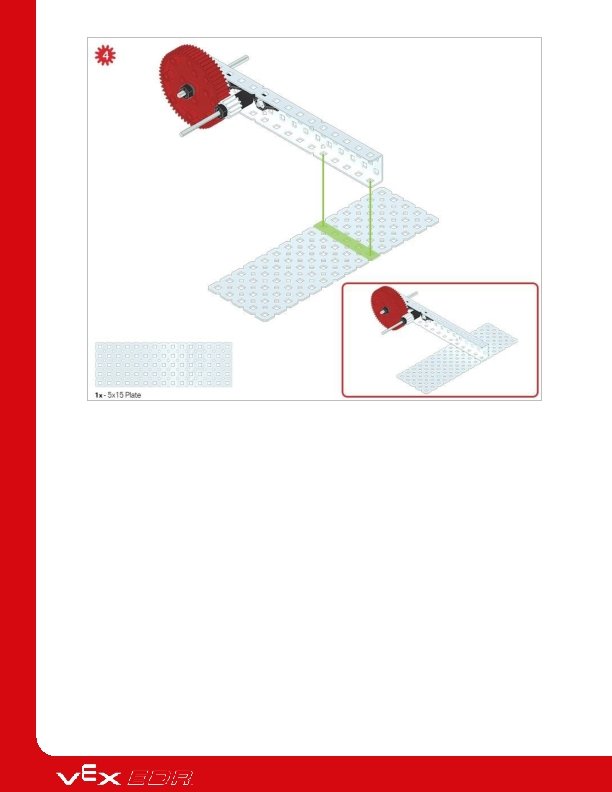
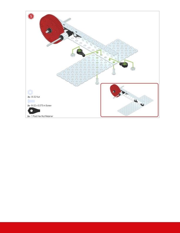
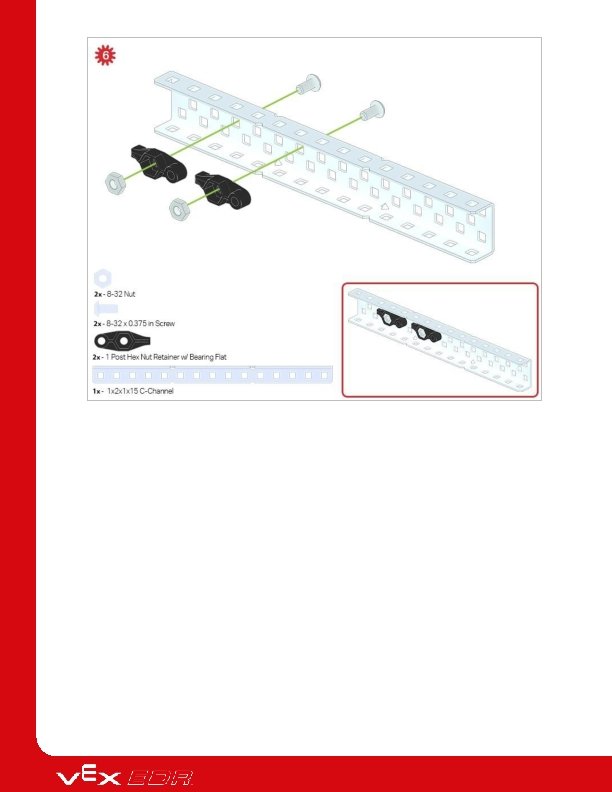
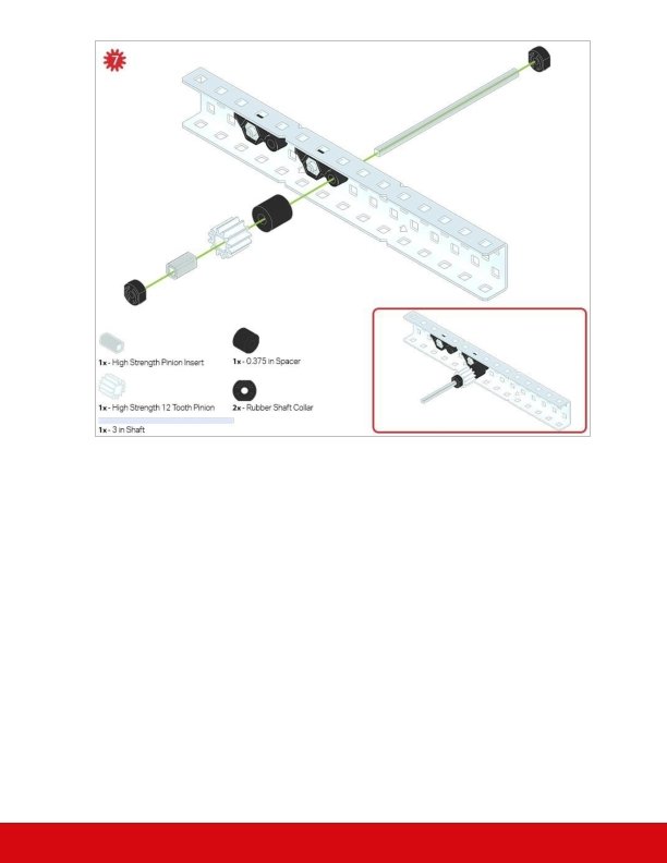
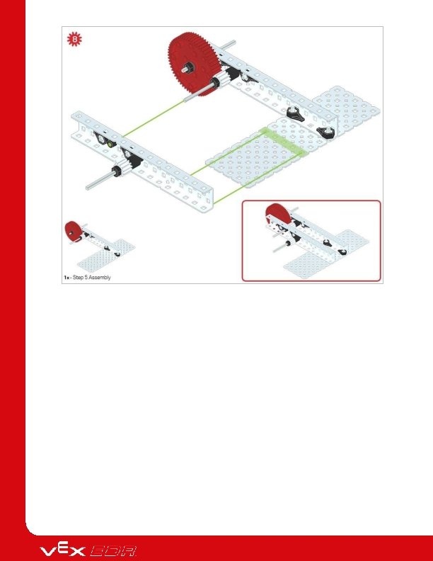
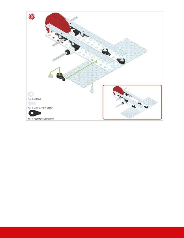
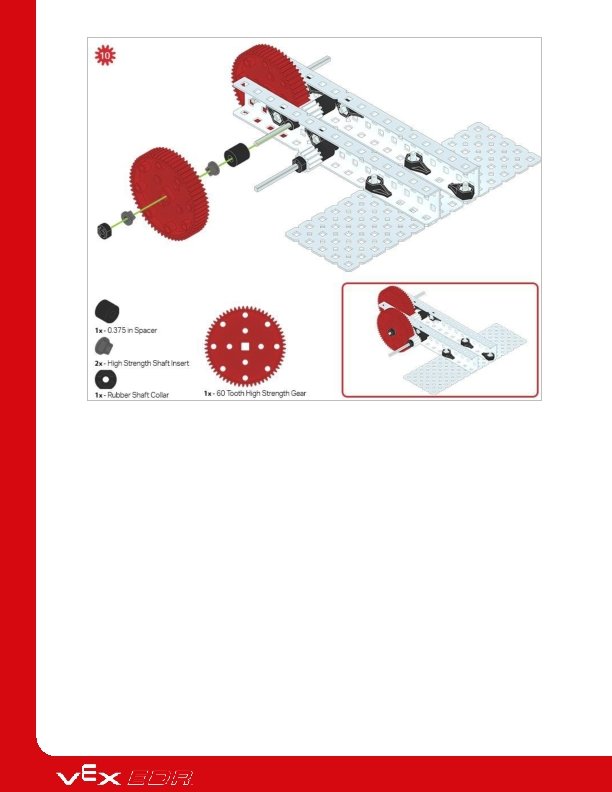
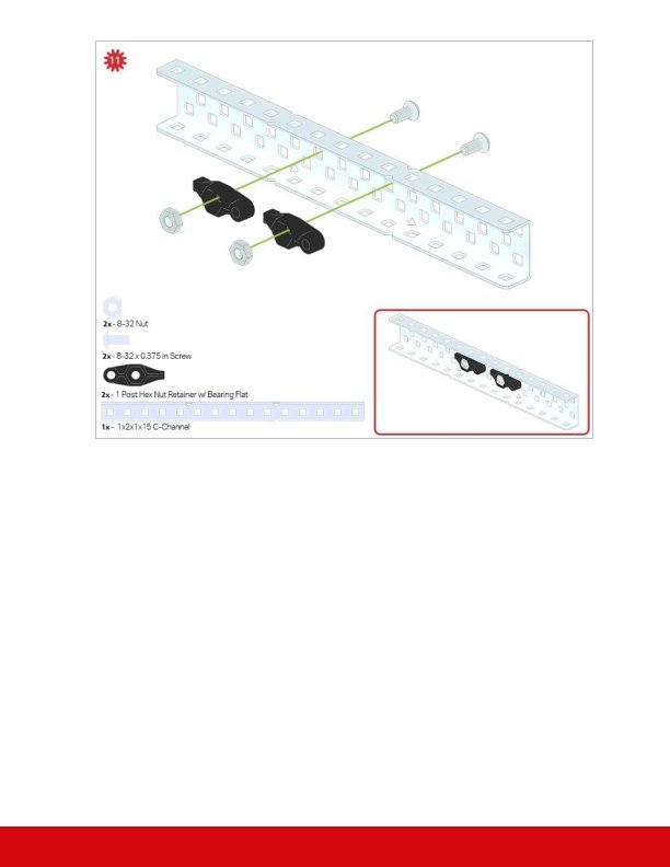
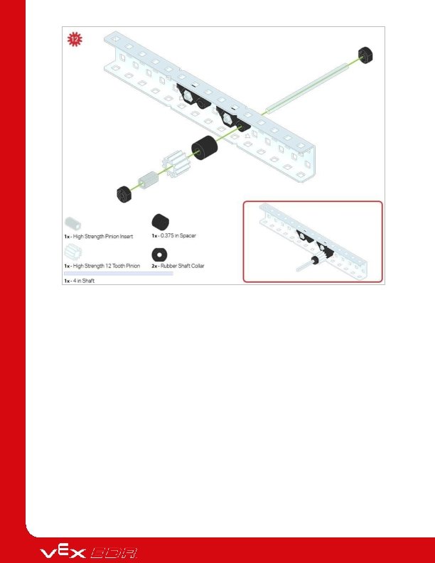
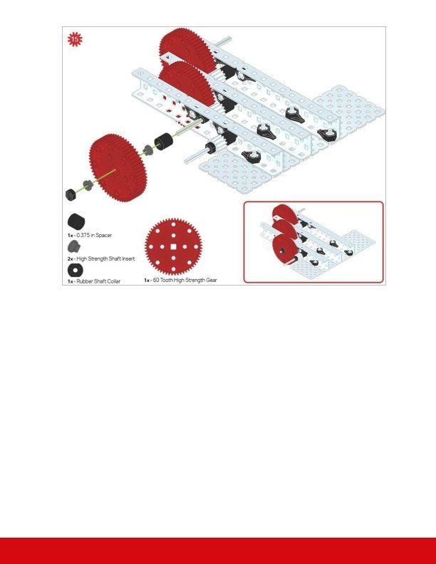
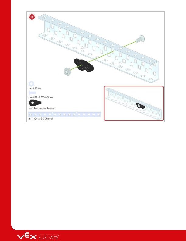
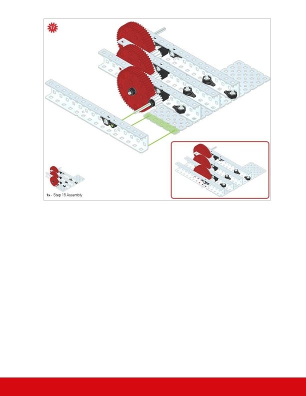
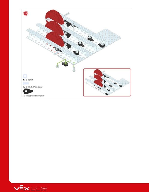
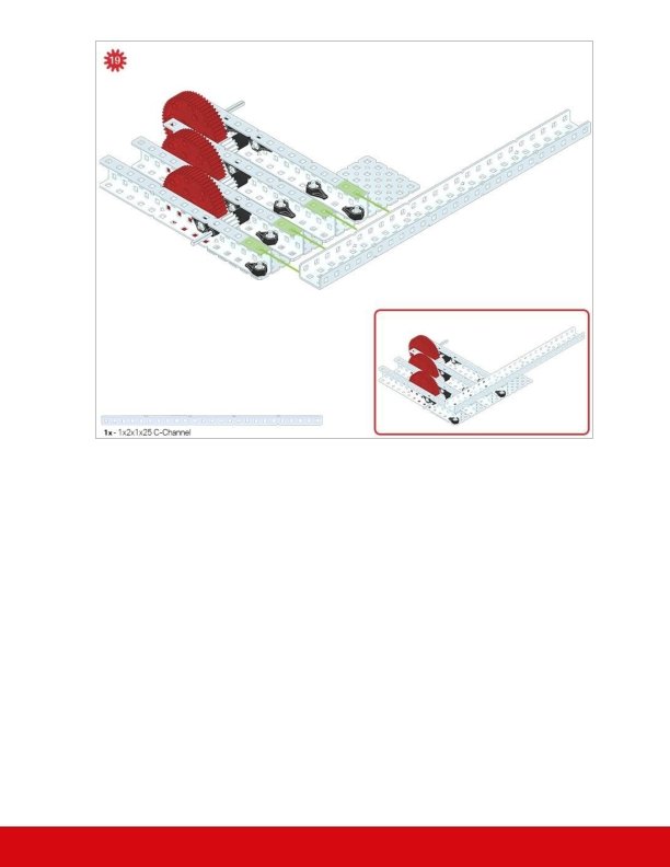
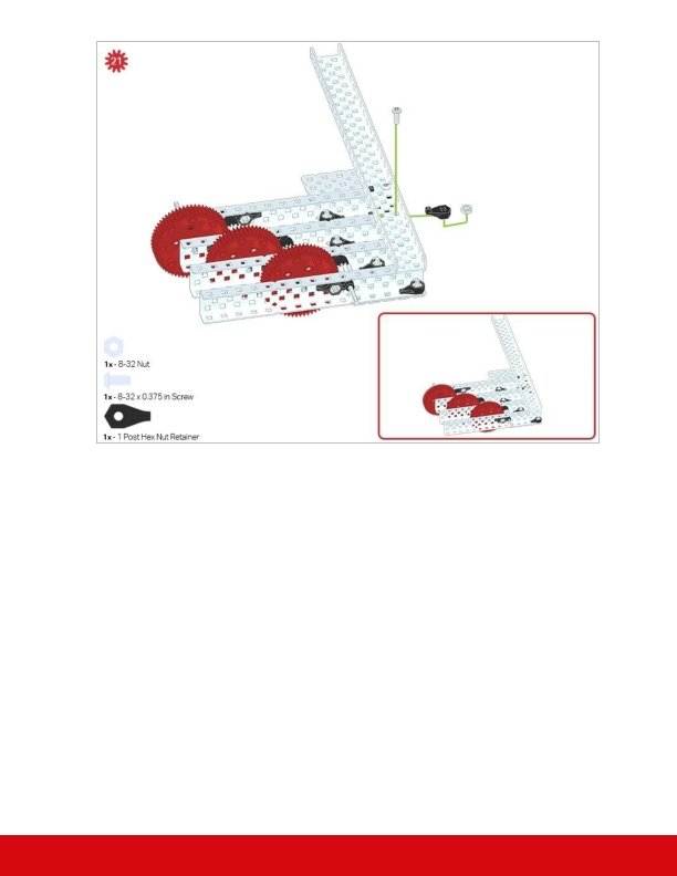
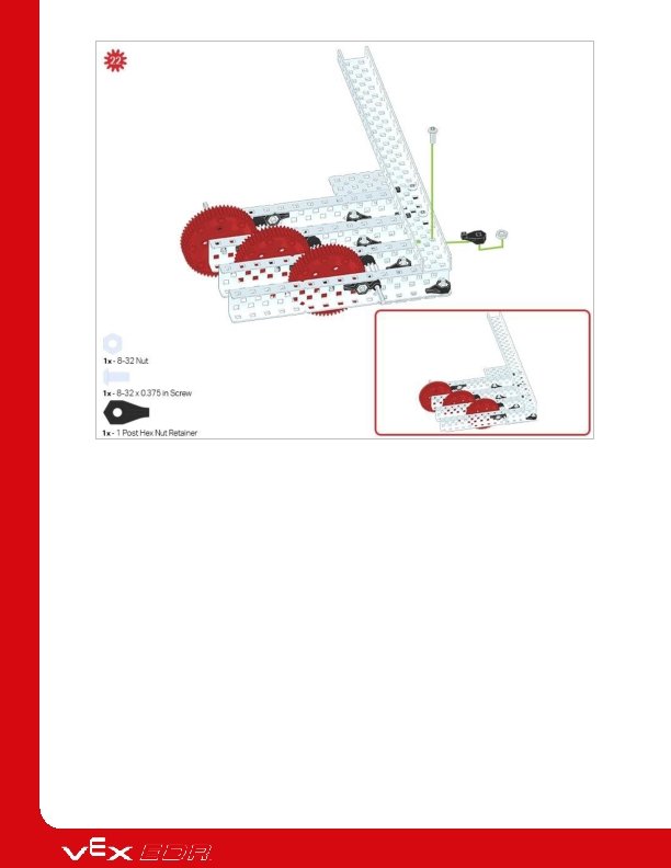
Build Instructions
Make sure that the High Strength 12 Tooth Pinion meshes with the 60 Tooth High Strength Gear in order for proper rotation to occur.
The green icon indicates that the build needs to be rotated (180 degrees).
Build Instruction Tips Check the Appendix for info on how to use the new Hex Nut Retainers.
Exploration Now that you've finished the build, test what it does. Explore with your build and then answer these questions in your engineering notebook. What does this build do? Explain with details. How might this build be used? Explain with details and sketches. Does the build have a mechanical advantage(s)? If so, how? What is the mechanical advantage? Explain with details. Which engineering terms are needed to explain this build to someone who has not seen it? Explain how each term describes this build. For example, if we were designing a roof for a house, I would say that the engineering term "pitch" is needed to describe this roof. Pitch describes the steepness of the slope in the roof. I could then use this term to better describe what I was building. Here are some suggested terms for the mechanical advantage exploration: "gear ratios", "idler gear", "speed", etc.
Test your build, observe how it functions, and fuel your logic and reasoning skills through imaginative, creative play.
Building Mechanical Advantage with Gears One larger gear rotation results many smaller gear rotations Different Sizes and Types of Gears A gear's circumference has a direct impact on how the gear transmits torque and speed. When two gears are meshed a mechanical advantage is produced if the circumference of the gears differs. This results in a change to the speed and torque of the axles attached to the gears. This change is proportional to the number of teeth in the gear. VEX gears have teeth of the same size and spacing. This helps to prevent slippage between gears, ensuring that the attached axles are always synchronized with each other. Having similarly sized and spaced teeth also enables the user to determine the gear ratio.
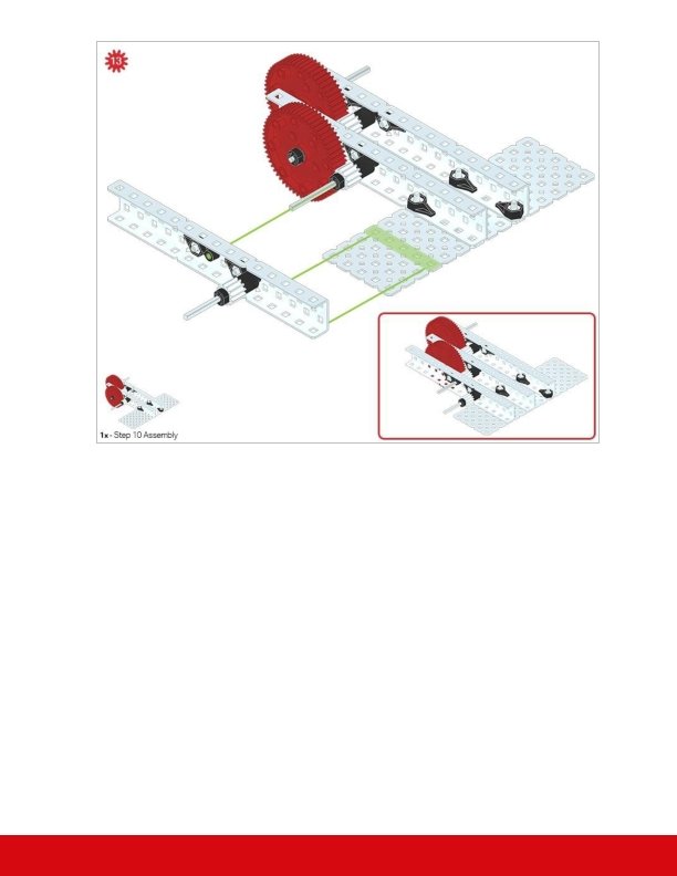
Applying Gears to this Build 1. The Gears in a Single Layer of the V 5 Gear Box Build Step 10 of the V 5 Gear Box build In every layer of the gearbox, you meshed a 12 -tooth gear with a 60 -tooth gear. Notice that the 60 -tooth gear is on the shaft that turns when you turn the shaft lock plate. When the 60 tooth gear turns, it turns the 12 -tooth gear. That means that on this side of the gearbox, the 60 -tooth gear is the driving gear and the 12 -tooth gear is the driven gear. Locate three locations in the build where a 60 -tooth gear drives a 12 -tooth gear. Hint: It matters which shaft you're turning. You can use a Shaft Collar extended to a wheel or another shaft-locked part to make it easier. Since there are 5 times as many teeth on the larger gear, our gear ratio is 5: 1, meaning every 5 turns of the smaller gear, the larger gear will turn 1 time.
2. Using a Larger Gear as an Input for Increased Speed Using a 60 -tooth gear to drive a 12 -tooth gear We can measure rotational speed around an axle. In the example above, we are turning or driving the large gear. For each 1 turn around for the larger, driving gear, the smaller gear has to turn 5 whole times around. This means that the smaller gear will spin 5 times as fast as the larger gear, due to the 5: 1 gear ratio. This is known as high gear ratio; the ratio is higher than 1: 1.
3. Using a Smaller Gear as an Input for Increased Torque Using a 12 -tooth gear to drive a 60 -tooth gear Torque is a measure of how hard you turn something about a center point. You can calculate it by multiplying the force of a push by how far away the push is from the center point. Since the teeth of the smaller, driving gear are close to the center, they push with more force for the same amount of torque. At the same time, the teeth of the driven gear are far away from the center point, so the same amount of force creates more torque. If you have a larger driving gear, the torque you need to apply to the shaft is much higher than if you were driving a smaller gear. Since we can attach multiple gears to the same shaft, we can adjust the amount of force from the same torque, resulting higher torque with each link. The resultant gear ratio from each stage of our V 5 Gear Box is 1: 5, a low gear ratio. The driving gear will have to turn further to move the driven gear, but it will make the driven gear push harder.
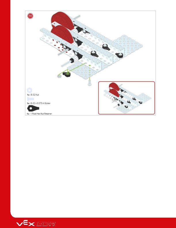
4. Multiplying Mechanical Advantage The gearbox, showing high and low geared shafts. Each stage has a 5: 1 gear ratio, so we can multiply them together to make 5 x 5 x 5: 1 x 1 x 1, or 125: 1 ratio between input and output shafts. That means that if you turn the high-geared shaft 1 time all the way around, the output shaft will turn 125 times! On the other hand, if you apply some torque to the low-geared shaft, the output shaft will output with a torque 125 times as high, but it will do it very slowly. Try turning the high geared shaft with no resistance. How quickly does the output shaft turn? Try turning the low geared shaft while holding the output shaft. Can you stop the output shaft from turning?
Become a 21 st century problem solver by applying the core skills and concepts you learned to other problems.
Where We've Seen Torque or Speed The chain and sprockets of a bicycle Pedal Faster or Pedal Stronger! When riding a bicycle, maintaining a certain pedaling speed (also called cadence) regardless of hills or flat road is important. To transfer power from the pedal to the wheels involves the usage of gears. There are two places that gears exist on a bicycle. The first is connected to the pedal, called the chainring. The second place is connected to the back tire, called the rear cog or sprocket. The gears are connected by a chain. The chain transfers the power applied at the pedal to the wheels and a mechanical advantage is created based on the size of gears connected to the pedals (front cassette) and wheels (rear cassette). There are different bikes with varying numbers of gears called chainrings and sprockets. A
single gear bike remains at a fixed mechanical advantage - the gears that are on a single gear bike will not change regardless if the person is pedaling on a flat road or a hill. This means the person pedaling has to put all of the strain on their legs in order to climb hills or ride much faster. A multi-geared bike allows the person pedaling to maintain the same pedaling speed to adjust their mechanical advantage to reach different outcomes. This enables the rider to climb hills or travel faster without changing their pedaling speed. A bicycle with multiple gears gives many options to use mechanical advantage to their personal advantage. A bicycle at a stand-still would want to use a gear combination suited for more torque (turning power) in order to accelerate from a stop or to climb a large hill. A mechanical advantage for torque (more turning power) is achieved when a smaller gear drives a larger gear. In the context of a bicycle, this happens when the smallest front chainring size is paired with the largest rear cog or sprocket. However, a bicycle geared for torque will not be able to move very quickly. On the other hand, a bicycle that is already moving and wants to reach a fast speed needs to use a gear combination suited for more speed (rate of motion) in order to achieve a high speed without having to pedal hundreds of times per minute. A mechanical advantage for speed is achieved when a larger gear drives a smaller gear. In the context of a bicycle, this happens when the largest front chainring size is paired with the smallest rear cog or sprocket. Having a mechanical advantage when biking allows riders to get the most out of the amount of energy they exert. A mechanical advantage can be applied in many different situations and become desirable when designing a robot for a competition.
Designing for Torque or Speed Advantages VEX V 5 Clawbot Torque or Speed in Robotics Competitions Whether you build in a torque or speed advantage on your robot will depend on the weight of the objects it interacts with (how heavy the robot's part is, how much force it will need to do its task), and how quickly or carefully you want a task done (moving around the field vs. carefully grabbing and moving a game piece). It is helpful to consider using torque or speed advantages to accomplish tasks similar to these: Moving the entire robot around the field - speed advantage Lifting and moving large robot arms or claws - torque advantage Controlling a claw to hold game objects firmly - torque advantage Moving a small part that collects small game objects - speed advantage
It is important to read and consider the rules of a competition so that you can build a competition robot for speed and strength in a strategic manner.
Is there a more efficient way to come to the same conclusion? Take what you’ve learned and try to improve it.
Improve Your Build Answer the following questions in your engineering notebook as you tinker with the build. What would you change about the build if you wanted to improve it? Explain at least one change. What steps will you follow to change the build? Explain with details and/or sketches. Do your changes to the build make it work more efficient or powerful? Explain how. Or, do the changes make the build usable for more tasks? Will more people want to use it after the change? Explain how the change affects how it is used. Make your changes to the build and then test them. Did your changes make the build better? Explain how, or why not. How many times did you try to change the build? What happened during each try? Explain. Is there a change you would like to make but need additional pieces? Explain with details and/or sketches.
Understand the core concepts and how to apply them to different situations. This review process will fuel motivation to learn.
Review 1. You can use gears in your robot to . o create a torque advantage o create a speed advantage o create either torque or speed advantages, depending on what the robot needs to do o None of the above 2. If you were riding a bicycle, how would you be using gears? o Changing gears lets you pedal more easily or makes you need more force to pedal. o Changing gears lets your pedaling make you move farther or shorter distances. o Changing gears lets you pedal easily up steep hills or quickly across even surfaces. o All of the answers are correct. 3. If gears are connected together as in a gear box, how do you calculate the total gear ratio? o Add each gear ratio in the chain o Multiply each gear ratio in the chain o Divide the teeth on the first driving gear by the teeth on the final, output gear o None of the answers are correct. 4. True or False: A gear box can demonstrate a high or low gear configuration. o True o False 5. Which configuration will result in the highest torque output? o Small driving gear, small driven gear o Small driving gear, large driven gear o Large driving gear, small driven gear
o Large driving gear, large driven gear 6. The driven gear . o does the turning o is turned by the driving gear o is always smaller than the driving gear o is always larger than the driving gear
Additional information, resources, and materials.
Using the 1 Post Hex Nut Retainer w/ Bearing Flat The 1 Post Hex Nut Retainer w/ Bearing Flat allows shafts to spin smoothly through holes in structural components. When mounted, it provides two points of contact on structural components for stability. One end of the retainer contains a post sized to securely fit in the square hole of a structural component. The center hole of the retainer is sized and slotted to securely fit a hex nut, allowing a 8 -32 screw to easily be tightened without the need for a wrench or pliers. The hole on the end of the Retainer is intended for shafts or screws to pass through. To make use of the retainer: Align it on a VEX structural component such that the end hole is in the desired location, and the center and end sections are also backed by the structural component.
Insert the square post extruding from the retainer into the structural component to help keep it in place. Insert a hex nut into the center section of the retainer so that it is flush with the rest of the component. Align any additional structural components to the back of the main structural component, if applicable. Use an 8 -32 screw of appropriate length to secure the structural component(s) to the retainer through the center hole and hex nut.
Using the 4 Post Hex Nut Retainer The 4 Post Hex Nut Retainer provides five points of contact for creating a strong connection between two structural components using one screw and nut. Each corner of the retainer contains a post sized to securely fit in a square hole within a structural component. The center of the retainer is sized and slotted to securely fit a hex nut, allowing a 8 -32 screw to easily be tightened without the need for a wrench or pliers. To make use of the retainer: Align it on a VEX structural component such that the center hole is in the desired location, and each corner is also backed by the structural component. Insert the square posts extruding from the retainer into the structural component to help keep it in place. Insert a hex nut into the center section of the retainer so that it is flush with the rest of the component.
Align any additional structural components to the back of the main structural component, if applicable. Use an 8 -32 screw of appropriate length to secure the structural component(s) to the retainer through the center hole and hex nut.
Using the 1 Post Hex Nut Retainer The 1 Post Hex Nut Retainer provides two points of contact for connecting a structural component to another piece using one screw and nut. One end of the retainer contains a post sized to securely fit in the square hole of a structural component. The other end of the retainer is sized and slotted to securely fit a hex nut, allowing a 8 -32 screw to easily be tightened without the need for a wrench or pliers. To make use of the retainer: Align it on a VEX structural component such that both ends are backed by the structural component and positioned to secure the second piece. Insert the square post extruding from the retainer into the structural component to help keep it in place. If the retainer is being used to secure two structural components, insert a hex nut into the other end of the retainer so that it is flush with the rest of the component. If used to secure
a different type of component, such as a standoff, it may be appropriate to insert the screw through this side. Align any additional components to the back of the main structural component, if applicable. If the retainer is being used to connect two structural components, use an 8 -32 screw of appropriate length to secure the structural components through the hole and hex nut. If used to connect a different type of component, such as a standoff, secure it directly or with a hex nut.
Engineering Notebooks Alexander Graham Bell's notebook entry from a successful experiment with his first telephone An Engineering Notebook Documents your Work Not only do you use an engineering notebook to organize and document your work, it is also a place to reflect on activities and projects. When working in a team, each team member will maintain their own journal to help with collaboration. Your engineering notebook should have the following: An entry for each day or session that you worked on the solution Entries that are chronological, with each entry dated Clear, neat, and concise writing and organization Labels so that a reader understands all of your notes and how they fit into your iterative design process An entry might include: Brainstorming ideas Sketches or pictures of prototypes
Pseudocode and flowcharts for planning Any worked calculations or algorithms used Answers to guiding questions Notes about observations and/or conducted tests Notes about and reflections on your different iterations