MEC 0011 Statics Lecture 7 Prof Sanghee Kim


 Floor beam (바닥보) Joint")


- Slides: 20
MEC 0011 Statics Lecture 7 Prof. Sanghee Kim Fall_ 2012
Chapter Objectives - Determine the forces in the members of a truss using the method of joints and the method of sections - Analyze forces acting on the members of frames and machines composed of pinconnected members Chapter Outline 1. 2. 3. 4. Simple Trusses The Method of Joints Zero-Force Members The Method of Sections
6. 1 Simple Trusses • A truss composed of slender members joined together at their end points Planar Trusses (평면트러스) • • Planar trusses used to support roofs and bridges Roof load is transmitted to the truss at joints(연결부) by means of a series of purlins(마룻대)
• The analysis of the forces developed in the truss members is 2 D • Similar to roof truss, the bridge truss loading is also coplanar (동일평면선상)
- Load transmitting Deck Stringer (종재) Floor beam (바닥보) Joint
Assumptions for Design 1. “All loadings are applied at the joint” - Weight of the members neglected 2. “The members are joined together by smooth pins” - Assume connections provided the center lines of the joining members are concurrent Gusset plate (bolting & welding) (bolting & pin
• Importance of actual design of truss To state whether the nature of the force is tensile or compressive Compression members made thicker (due to bucking or column effect) • Force tend to elongate member tensile force • Force tend to shorten member compressive force
• Form of a truss must be rigid to prevent collapse • The simplest form that is rigid or stable is a triangle Expanding the basic triangular truss (connect more members to new joint D)
6. 2 The Method of Joints • For truss, we need to know the force in each members • Forces in the members are internal forces equilibrium not be applied • For external force members, equations of equilibrium can be applied • Force system acting at each joint is coplanar and concurrent • ∑Fx = 0 and ∑Fy = 0 must be satisfied for equilibrium
Procedure for Analysis • Draw the FBD with at least 1 known and 2 unknown forces • Find the external reactions at the truss support • Determine the correct sense of the member • Orient the x and y axes • Apply ∑Fx = 0 and ∑Fy = 0 • Use known force to analyze the unknown forces
Example 6. 1 Determine the force in each member of the truss and indicate whether the members are in tension or compression.
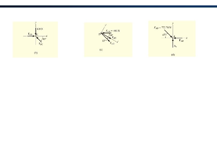
Solution 2 unknown member forces at joint B 1 unknown reaction force at joint C 2 unknown member forces and 2 unknown reaction forces at point A For Joint B,
For Joint C,
For Joint A,
- FBD of each pin shows the effect of all the connected members and external forces applied to the pin - FBD of each member shows only the effect of the end pins on the member
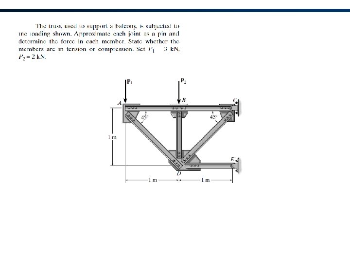
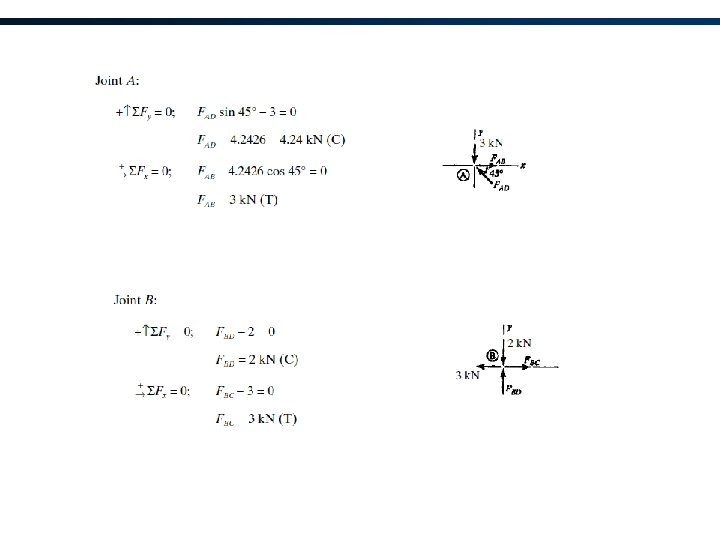
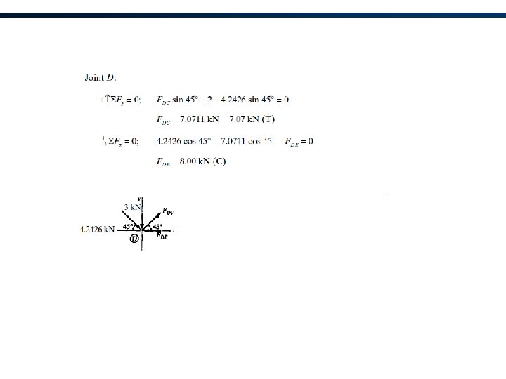
Example 6. 2 Determine the force in each member of the truss and indicate whether the members are in tension or compression.