
MEC 0011 Statics Lecture 4 Prof Sanghee Kim
- Slides: 24
MEC 0011 Statics Lecture 4 Prof. Sanghee Kim Fall_ 2012
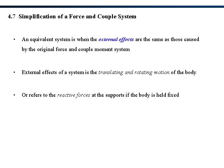
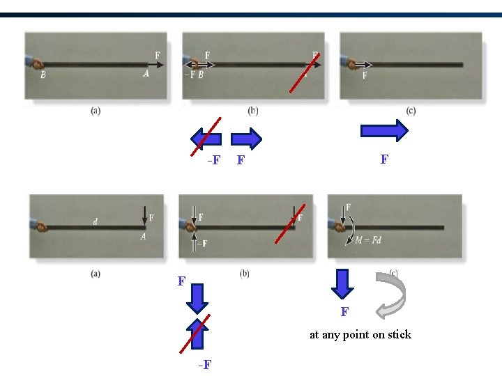
4. 7 Simplification of a Force and Couple System • An equivalent system is when the external effects are the same as those caused by the original force and couple moment system • External effects of a system is the translating and rotating motion of the body • Or refers to the reactive forces at the supports if the body is held fixed
-F F F at any point on stick -F
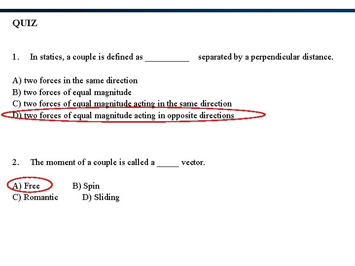
QUIZ 1. In statics, a couple is defined as _____ separated by a perpendicular distance. A) two forces in the same direction B) two forces of equal magnitude C) two forces of equal magnitude acting in the same direction D) two forces of equal magnitude acting in opposite directions 2. The moment of a couple is called a _____ vector. A) Free C) Romantic B) Spin D) Sliding
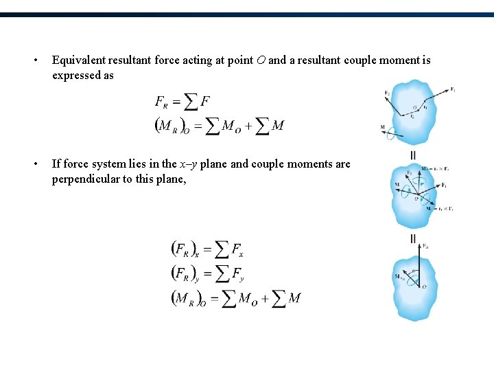
• Equivalent resultant force acting at point O and a resultant couple moment is expressed as • If force system lies in the x–y plane and couple moments are perpendicular to this plane,
Procedure for Analysis 1. Establish the coordinate axes with the origin located at point O and the axes having a selected orientation 2. Force Summation 3. Moment Summation
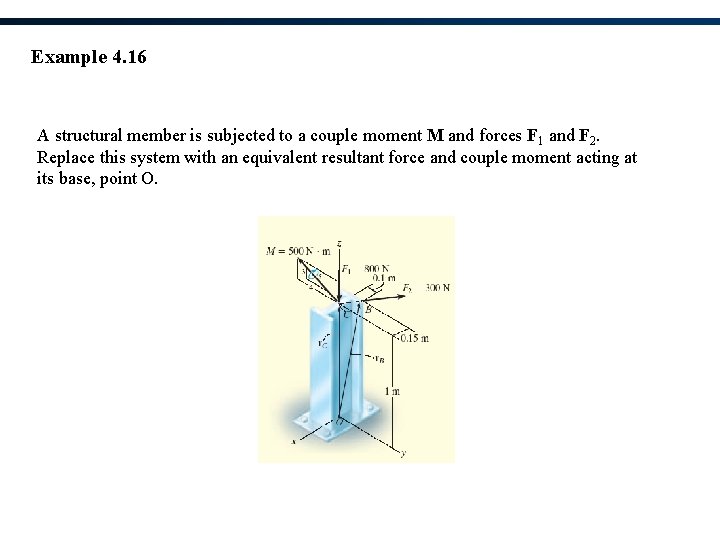
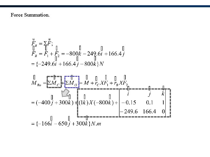
Example 4. 16 A structural member is subjected to a couple moment M and forces F 1 and F 2. Replace this system with an equivalent resultant force and couple moment acting at its base, point O.
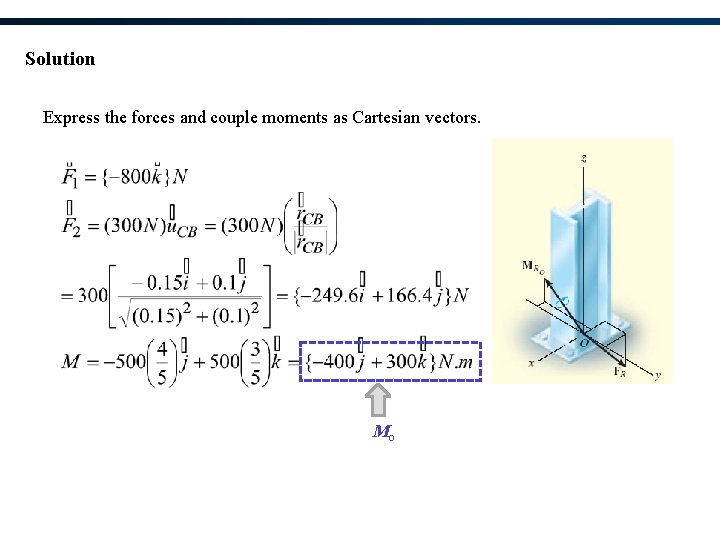
Solution Express the forces and couple moments as Cartesian vectors. Mo
Force Summation.
Chapter Objectives • Develop the equations of equilibrium for a rigid body • Concept of the free-body diagram for a rigid body • Solve rigid-body equilibrium problems using the equations of equilibrium
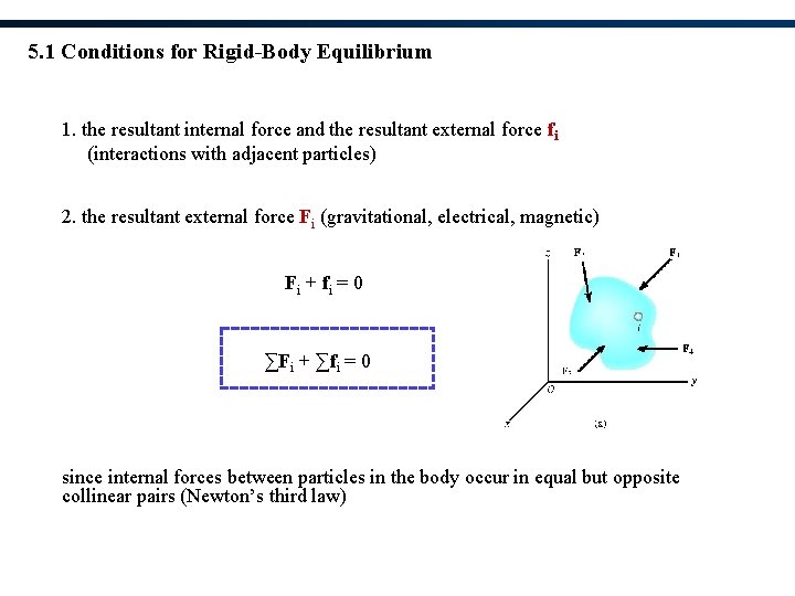
5. 1 Conditions for Rigid-Body Equilibrium 1. the resultant internal force and the resultant external force fi (interactions with adjacent particles) 2. the resultant external force Fi (gravitational, electrical, magnetic) F i + fi = 0 ∑Fi + ∑fi = 0 since internal forces between particles in the body occur in equal but opposite collinear pairs (Newton’s third law)
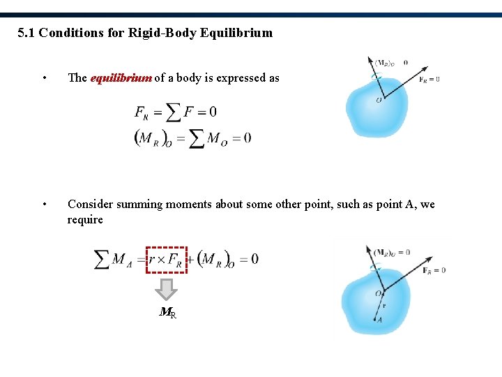
5. 1 Conditions for Rigid-Body Equilibrium • The equilibrium of a body is expressed as • Consider summing moments about some other point, such as point A, we require MR
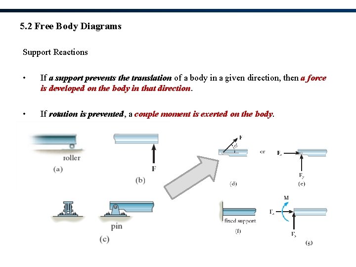
5. 2 Free Body Diagrams Support Reactions • If a support prevents the translation of a body in a given direction, then a force is developed on the body in that direction. • If rotation is prevented, a couple moment is exerted on the body.
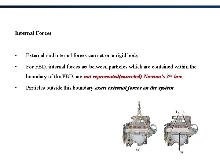
Internal Forces • External and internal forces can act on a rigid body • For FBD, internal forces act between particles which are contained within the boundary of the FBD, are not represented(canceled) Newton’s 3 rd law • Particles outside this boundary exert external forces on the system
Weight and Center of Gravity • Each particle has a specified weight • System can be represented by a single resultant force, known as weight W of the body • Location of the force application is known as the center of gravity
Procedure for Drawing a FBD 1. Draw Outlined Shape • Imagine body to be isolated or cut free from its constraints • Draw outline shape 2. Show All Forces and Couple Moments • Identify all external forces and couple moments that act on the body 3. Identify Each Loading and Give Dimensions • Indicate dimensions for calculation of forces • Known forces and couple moments should be properly labeled with their magnitudes and directions
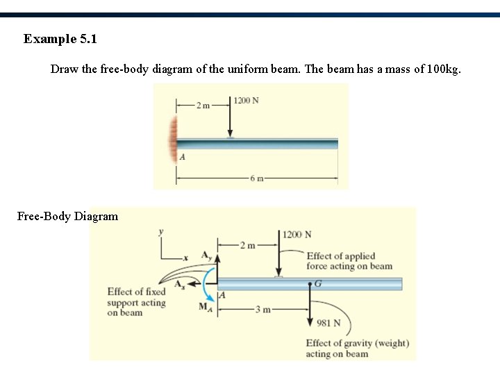
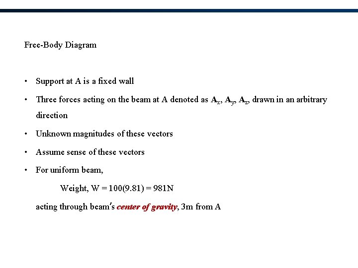
Example 5. 1 Draw the free-body diagram of the uniform beam. The beam has a mass of 100 kg. Free-Body Diagram
Free-Body Diagram • Support at A is a fixed wall • Three forces acting on the beam at A denoted as Ax, Ay, Az, drawn in an arbitrary direction • Unknown magnitudes of these vectors • Assume sense of these vectors • For uniform beam, Weight, W = 100(9. 81) = 981 N acting through beam’s center of gravity, 3 m from A
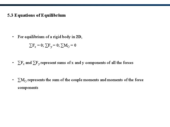
5. 3 Equations of Equilibrium • For equilibrium of a rigid body in 2 D, ∑Fx = 0; ∑Fy = 0; ∑MO = 0 • ∑Fx and ∑Fy represent sums of x and y components of all the forces • ∑MO represents the sum of the couple moments and moments of the force components
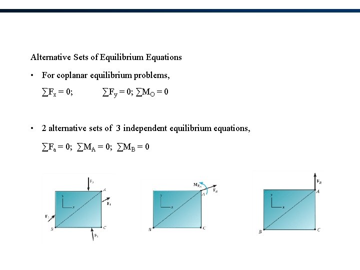
Alternative Sets of Equilibrium Equations • For coplanar equilibrium problems, ∑Fx = 0; ∑Fy = 0; ∑MO = 0 • 2 alternative sets of 3 independent equilibrium equations, ∑Fa = 0; ∑MA = 0; ∑MB = 0
Procedure for Analysis Equations of Equilibrium • Apply ∑MO = 0 about a point O • Unknowns moments of are zero about O and a direct solution the third unknown can be obtained • Orient the x and y axes along the lines that will provide the simplest resolution of the forces into their x and y components • Negative result scalar is opposite to that was assumed on the FBD
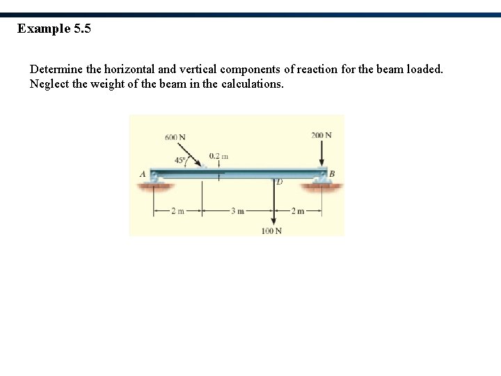
Example 5. 5 Determine the horizontal and vertical components of reaction for the beam loaded. Neglect the weight of the beam in the calculations.
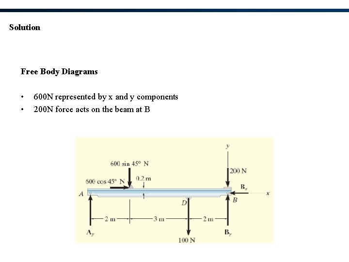
Solution Free Body Diagrams • • 600 N represented by x and y components 200 N force acts on the beam at B
Equations of Equilibrium