Measurement of Geophysical Effects with large scale gravitational


 in mrad/Hz-1/2; LC (red) – local")

 data vs. prediction for 5 days, December 7, 2006 (Neither the phase or")


 the mean pseudo spectrum of the")
")
=Re{ E 1*(t) exp jω0")
 = E 1*(t) g*(t) , → E 1*( )")
 OS Transfer Function")
![E 1(t) ~ [A + a(t)] → a(t) = 0 central mode regime: VS(t)](https://slidetodoc.com/presentation_image_h2/e052560a484591f3fcf01cac14938018/image-31.jpg "E 1(t) ~ [A + a(t)] → a(t) = 0 central mode regime: VS(t)")
![neighbour mode regime : a*(t) ≠ 0 VS Re[<a*(t) g*(t)>j G ( m)] ;](https://slidetodoc.com/presentation_image_h2/e052560a484591f3fcf01cac14938018/image-32.jpg "neighbour mode regime : a*(t) ≠ 0 VS Re[<a*(t) g*(t)>j G ( m)] ;")
 = GR( ) G( )")


- Slides: 36
Measurement of Geophysical Effects with large scale gravitational interferometers V. N. Rudenko Sternberg Astronomical Institute, MSU Part I : Physical mechanisms for geodynamical signals in Virgo. GGD Workshop 17 -18 April 2012, IPGP, Paris (France)
Introduction
at quasi static frequencies VIRGO interferometer can be considered as a conventional two coordinate strain meter, four points tilt meter and as a new type of gravity field gradiometer
Sensing of pure gravity field variations
Geo-application of GW-interferometers Estimates of Virgo intrinsic noises
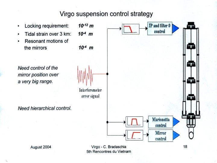
Virgo control circuit signals
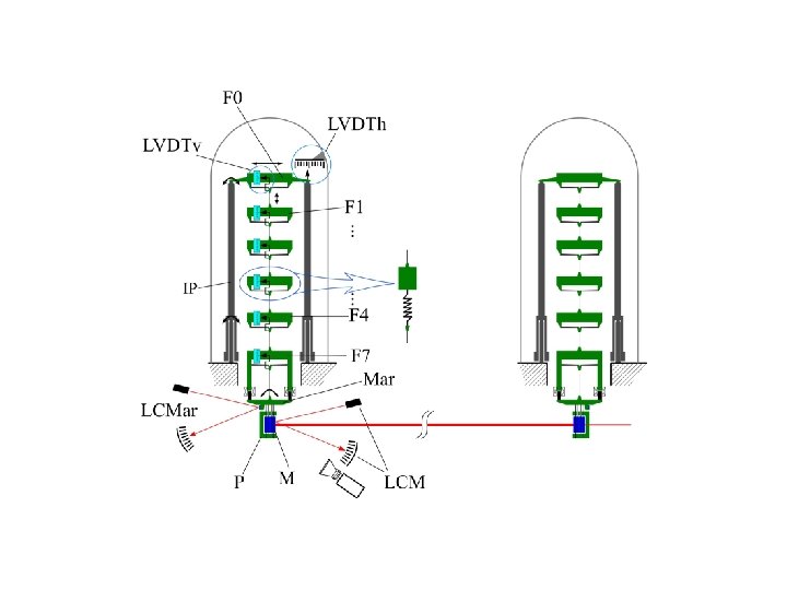
The vacuum chambers of Virgo Central Area West input Power Recycling Nord input Beam Splitter Signal Recycling
Principle scheme of the VIRGO angular control system
recycling mirror angular noise (around the beam direction) in mrad/Hz-1/2; LC (red) – local control regime ; GC (black) – global control regime. .
Geo signals at the main output
(LIGO) data vs. prediction for 5 days, December 7, 2006 (Neither the phase or amplitude have been normalized) It is assumed: ht = g||L/c 2 LIGO tidal signal at FSR-frequency ~ 37 k. Hz Meliessinos A. , MG-12 Paris, July 12– 18, 2009; http: //xxx. lanl. gov/PS, cache/arxiv/pdf/1001. 558 v. 2. pdf. Forrest C. V. , Tidal Effects on Laser Gravitational Wave Detectors, Thesis Univ. of Rorester, LIGO Document P 09 0000 v 1 (2009).
. ISSN 0021_3640, JETP Letters, 2010, Vol. 91, No. 10, pp. 495– 499. © Pleiades Publishing, Inc. , 2010. Original Russian Text © A. V. Gusev, V. N. Rudenko, 2010, published in Pis’ma v Zhurnal Йksperimental’noі i Teoreticheskoі Fiziki, 2010, Vol. 91, No. 10, pp. 543– 547. Gravitational Modulation of the Optical Length of Long Baseline Laser Interferometers A. V. Gusev* and V. N. Rudenko** Sternberg Astronomical Institute, Moscow State University, Universitetskii pr. 13, Moscow, 119992 Russia * e_mail: avg@sai. msu. ru ** e_mail: rvn@sai. msu. ru Received February 15, 2010 The effect of quasi static variations of the Earth’s gravitational field on the output signal of long baseline gravitational-wave interferometers has been considered. The relativistic representation of the gravitational field in the form of a varying refractive index is used. An analytical calculation with numerical estimates of the tidal effect has been performed to explain the recent results observed on the LIGO interferometers
Pump with a finite width of line pump frequency pedestal width FSR interval neighbors mode
Mechanism FSR-harmonic at the main output relativistic gravity effect ! PD in the “dark spot”
phase difference at the PD n – tidal variation modulation index ~ 0. 02 % observable value ~ 1 % observable effect was too big in respect of RG estimate
A. Melissinos GR «red shift model»
If it is not GR effect, … then what ? the only hypothesis it is a residual arm shift… L const. behind the control accuracy ~ L= 10 -10 cm tidal LT~ 10 -7 L residual t-deformation ~ 10 -10/3· 105 = 10 -16 GR effect (10 -7 g 0 L/c 2 ) F ~ 5· 10 -18
(Frasca effect: Sidereal periodicity in Virgo noise data) the mean pseudo spectrum of the noise in the region 22 Hz
Interferometer Optical Scheme (without recycling mirror)
analysis logic optical pump: OS – optical system configuration E(t)=Re{ E 1*(t) exp jω0 t} , ω0 - carrier → E 1*(t) = [A* + a*(t)] exp{ j sin mt } , L ~ L 1 L 2 → L ; (0) = ω0( 1 + ) , - geo length variations = l/L , = c/2 L = 1 - 2 = st + gw static variations + gw-signal frequencies) (quasi
OS output → E 2(t) = E 1*(t) g*(t) , → E 1*( ) g*(t- )d ; g(t) – OS impulse characteristic frequencies: G(0), G( 1) transf. functions G( m) (0) = ω0(1 + ) – central mode (0) = ω0(1 + ) 2 FSR – side modes (0) = ω0(1 + ) m - sidebands G ( m) = G( m) + G( m) G ( m) = G( m) G( m) symmetric TF PD output → quadratures: VS , VC output signals VS Re [ A G(0) + < a(t) g(t) ] j. G+ ( m) VC Re [ A G(0) + < a(t) g(t) ] j. G ( m)
( k = 0 center , k = 1 side modes) OS Transfer Function G( (k)) 1 -exp j[ 0(2 l/c)+ ] exp j[k ( /(1 -r))( L/L)] l ~ ~ = 1( ) - 2( ) ={2 /(1 -r)} (L/ ) , l = < l>+ l “dark spot”→ 4( l/ ) + st/ =0, → lopt (L/2(1 r)) st main point: G( ) f ( st , l ) → coupled values! st gw ( st + gw)
E 1(t) ~ [A + a(t)] → a(t) = 0 central mode regime: VS(t) 0 , E 1 ~ A VC(t) A Re [ G*(0) j G+( m)] VC(t) A [4( l/ ) + ( st + gw)/ ] m( l/c) , l = < l > + l st l = lopt = [L/2(1 -r)] st VC(t) A gw m (< l > + l)/c (Frasca effect ? ) hgw ~ (1+ cos st) sin ( t + )
neighbour mode regime : a*(t) ≠ 0 VS Re[<a*(t) g*(t)>j G ( m)] ; VC {G ( m)] V(t) = VC + j VS ; → {FSR filter} → V (t) → 2 Melissinos regime FSR amplitude modulation 2 [|G(1)|2+|G( 1)|2] [|G+( m )|2+|G ( m )|2] lopt dark spot [4( l/λ) + (( st + gw)/ ]2 +[ΔL/L(1 r)]2 → no linear effect! But if l ≠ lopt → l = lopt+ ler ← a small detuning 2 4( l/λ) ( st + gw)/ Melissinos effect reconstruction ; ; [ m = L/(1 r) ler ] change ler – satisfies exp. data
Interferometer with power recycling mirror. Transfer Function GI( ) = GR( ) G( ) recycling cavity TF . model: MR - FP composed by (Michelson – FP arms cavity) tuning parameters: l = l 1 – l 2 , l. R = l. RB + li «geo amplitude modulation» of ITF output spectral components is kept but more powerful and with a new tuning
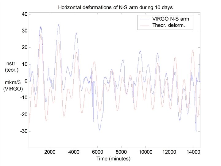
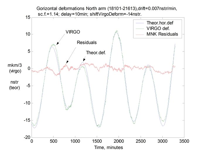
Conclusions • • • . Geophysical information from GW interferometers can be readout using compensation signal of circuits controlling the device operation regime. - besides due to parametric variations of FP resonance frequencies Geo - information might be received through the amplitude modulation of the free spectral range frequency filtered at the main interferometer output. Noise spectral density at the main output also is modulated by very slow (quasi static) variations of the interferometer base, produced by geophysics. It was demonstrated that VIRGO can be used as a two coordinate very long base strain meter. However the quality of the data strongly depends on a number of operational regime brakes during the observational time. Idea of measuring relative angular variations of mirror’s “plumb lines” for a sensing pure “gravity perturbations” up to now was not realized and requires a more detailed study.
11 Radical method for the linear parametric response reconstruction would be a using the two mode pump at neighbor frequencies ω0 and 1= 0+ωfsr “dark spot” condition is kept for the mode ω0 ; A residual part of the mode 1 iteracting at photo diode with radio sideband ω1+ r will produce directly at the Pound-Drever mixer output a low frequency signal I(t) proportional to the optical length variations . A possibility of application this method for a registering weak global geodynamical effects as well as detection of very low frequency GW is under the process in SAI MSU
Thanks for attention !