ME 521 Computer Aided Design 9 Solid Modeling


 C A-B Dr.")


 • • • 9. Solid Modeling The boundary representation method represents")
 Vertices 9. Solid Modeling Edges Faces Dr. Ahmet Zafer Şenalp ME")
 § Vertex is a unique point in space 9. Solid Modeling")
 9. Solid Modeling Ø Solid modelers store more information (geometry and")
 9. Solid Modeling A Loop is an ordered alternating sequence of")
 9. Solid Modeling Validity of B-Rep • To ensure topological validation")
 9. Solid Modeling Or in other terms by including the number")
 • • • 9. Solid Modeling Based on these definitions, neither")


 Feature modeling, in brief,")


- Slides: 63
ME 521 Computer Aided Design 9. Solid Modeling Assoc. Prof. Dr. Ahmet Zafer Şenalp e-mail: azsenalp@gmail. com e-mail: Mechanical Engineering Department Gebze Technical University
History of Geometric Modeling • • • 9. Solid Modeling 1967 Surface Modeling(S. A. Coons) 1973 Solid Modeling– Constructive Solid Geometry (Laning et al. , Draper Lab. ) 1973 Solid Modeling– Boundary Representation (Ian Braid, Cambridge U. ) 1985 Feature Based Modeling (Pratt & Wilson) 1990 Parametric Modeling (PTC) Dr. Ahmet Zafer Şenalp ME 521 Mechanical Engineering Department, GTU 2
9. Solid Modeling • Using volume information – weight or volume calculation, mass center calculation, moment of inertia calculation, – Finite element analysis model preperation • Using volume and boundary information – CNC code generation, robotics and assemblies Dr. Ahmet Zafer Şenalp ME 521 Mechanical Engineering Department, GTU 3
Half Space 9. Solid Modeling Unbounded geometric entities Each one of them divides the representation space into infinite portions, one filled with material and the other empty • Surfaces can be considered half-space boundaries and half spaces can be considered directed surfaces • An object is defined by the volume space contained within the defined boundary of the object Introduces the direction into the modeling, thus enables the topological information be stored in a geometric model • • Dr. Ahmet Zafer Şenalp ME 521 Mechanical Engineering Department, GTU 4
Half Space • • 9. Solid Modeling By specifying different boundary surface, we can have any half-spaces; The most commonly used half spaces: Planar Cylindrical Spherical Conical Toroidal By combining half-spaces (using Boolean operations) in a building block fashion, various solids can be constructed. Dr. Ahmet Zafer Şenalp ME 521 Mechanical Engineering Department, GTU 5
Properties of Solid Model 9. Solid Modeling The properties that a solid model or an abstract solid should capture mathematically can be stated as follows: 1. Rigidity. This implies that the shape of a solid model is invariant and does not depend on the model location or orientation in space. 2. Homogeneous three-dimensionality. Solid boundaries must be in contact with the interior. No isolated or dangling boundaries should be permitted. 3. Finiteness and finite describability. The former property means that the size of the solid is not infinite while the latter ensures that a limited amount of information can describe the solid. The latter property is needed in order to be able to store solid models into computers whose storage space is always limited. It should be noted that the former property does not include the latter and vice versa. For example, a cylinder that may have a finite radius and length may be described by an infinite number of planar faces. Dr. Ahmet Zafer Şenalp ME 521 Mechanical Engineering Department, GTU 6
Properties of Solid Model 9. Solid Modeling 4. Closure under rigid motion and regularized Boolean operations. This property ensures that manipulation of solids by moving them in space or changing them via Boolean operations must produce other valid solids. 5. Boundary determinism. The boundary of a solid must contain the solid and hence must determine distinctively the interior of the solid. Dr. Ahmet Zafer Şenalp ME 521 Mechanical Engineering Department, GTU 7
Solid Modeling Approaches 9. Solid Modeling • Constructive Solid Geometry: CSG • Boundary Representation: B-rep • Hybrid (Feature Based Modeling) Dr. Ahmet Zafer Şenalp ME 521 Mechanical Engineering Department, GTU 8
Constructive Solid Geometry • 9. Solid Modeling Based on simple geometric primitives – box – cone – sphere – etc. Dr. Ahmet Zafer Şenalp ME 521 Mechanical Engineering Department, GTU 9
Constructive Solid Geometry • 9. Solid Modeling Primitives are placed and combined by using boolean operations: – Union denoted by – Difference or subtraction denoted by – Intersection denoted by Dr. Ahmet Zafer Şenalp ME 521 Mechanical Engineering Department, GTU 10
Constructive Solid Geometry Example: 9. Solid Modeling C A (A-B) C A-B Dr. Ahmet Zafer Şenalp ME 521 Mechanical Engineering Department, GTU B 11
Constructive Solid Geometry Example: Dr. Ahmet Zafer Şenalp ME 521 Mechanical Engineering Department, GTU 9. Solid Modeling 12
Constructive Solid Geometry • 9. Solid Modeling All the operations are stored as a boolean tree rotation cylinder sphere Dr. Ahmet Zafer Şenalp ME 521 cylinder Mechanical Engineering Department, GTU 13
Boundary Representation (B-Rep) • • • 9. Solid Modeling The boundary representation method represents a solid as a collection of boundary surfaces. The database records both of the surface geometry and the topological relations among these surfaces. This representation is used mainly for graphical displays. Solids are represented by faces, edges and vertices. To enable the validity of the object topological rules should be guaranteed; – Faces are bounded with edges – Each edge should be shared with exactly 2 faces – Each edge should have a vertex at each end – At least 3 edges should connect at each vertex The surface must be closed Euler operations are used to construct B-rep models by combining faces, edges and vertices. Euler operation are lower level operations than boolean operations. Dr. Ahmet Zafer Şenalp ME 521 Mechanical Engineering Department, GTU 14
Boundary Representation (B-Rep) Vertices 9. Solid Modeling Edges Faces Dr. Ahmet Zafer Şenalp ME 521 Mechanical Engineering Department, GTU 15
Boundary Representation (B-Rep) § Vertex is a unique point in space 9. Solid Modeling § An Edge is a finite, non-self-intersecting, directed space curve bounded by two vertices § A Face is defined as a finite connected, non-self-intersecting, region of a closed oriented surface bounded by one or more loops
Boundary Representation (B-Rep) 9. Solid Modeling Ø Solid modelers store more information (geometry and topology) than wireframe or surface modelers (geometry only). Ø Geometry is the actual dimensions that define the entities of the object. Ø The geometry that defines the object shown in Figure 1 is the lengths of lines L 1, L 2 and L 3, the angles between the lines, and the radius R and the center P 1 of the half-circle. Ø Topology (sometimes called combinatorial structure), on the other hand, is the connectivity and associativity of the object entities. The topology of the object shown below can be stated as follows; Ø Ø L 1 shares a vertex (point) with L 2 and C 1 L 2 shares a vertex with L 1 and L 3 ; L 3 shares a vertex with L 2 and C 1. L 1 and L 3 do not overlap Same geometry but different topology (P 1 is inside/outside) Dr. Ahmet Zafer Şenalp ME 521 Same topology but different geometry Mechanical Engineering Department, GTU 17
Boundary Representation (B-Rep) 9. Solid Modeling A Loop is an ordered alternating sequence of vertices and edges. A loop defines a non-selfintersecting, piecewise, closed space curve which, in turn, may be a boundary of a face. A Handle (Genus or Through hole)is defined as a passageway that passes through the object completely. A Body (Shell) is a set of faces that bound a single connected closed volume. Thus a body is an entity that has faces, edges, and vertices
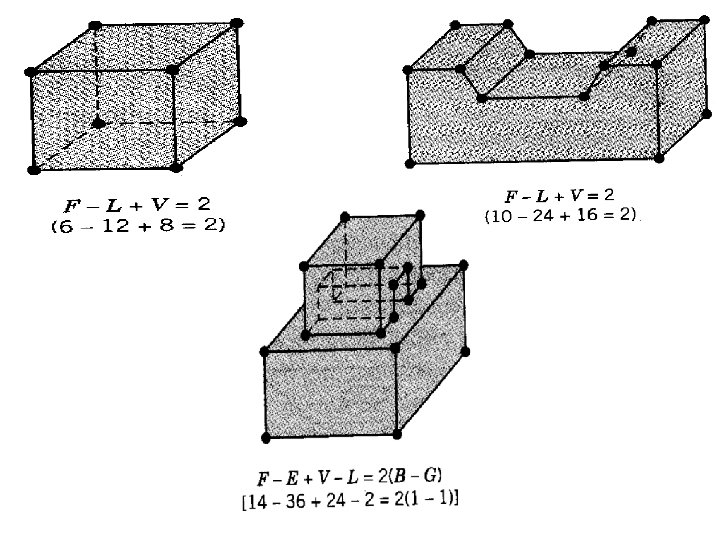
Boundary Representation (B-Rep) 9. Solid Modeling Validity of B-Rep • To ensure topological validation of the boundary model, special operators are used to create and manipulate the topological entities. These are called Euler Operators • The Euler’s Law gives a quantitative relationship among faces, edges, vertices, loops, bodies or genus in solids Geometry should obey Euler rules: V: Number of vertices E: Number of edges F: Number of faces 16 – 24 + 10 – 2 = 2 V-E+F=2 Dr. Ahmet Zafer Şenalp ME 521 Mechanical Engineering Department, GTU 19
Boundary Representation (B-Rep) 9. Solid Modeling Or in other terms by including the number of bodies (for multiple bodies) and handles; EULER LAW: F-E+V-L=2(B-G) Where F = number of faces E = number of edges V = number of vertices L = Faces inner loops B = number of bodies G = number of genus (handles) Dr. Ahmet Zafer Şenalp ME 521 Mechanical Engineering Department, GTU 20
Boundary Representation (B-Rep) • • • 9. Solid Modeling Based on these definitions, neither geometry nor topology alone can completely model objects. Wireframe and surface models deal only with geometrical information of objects, and are therefore considered incomplete and ambiguous. From a user point of view, geometry is visible, and topology is considered to be nongraphical relational information that is stored in solid model databases and is not visible to users. B-rep does not guarantee that a group of boundary surfaces should form a closed solid. Most CAD software uses both CSG and B-rep methods (hybrid structure). Dr. Ahmet Zafer Şenalp ME 521 Mechanical Engineering Department, GTU 22
Geomerty Construction With B-Rep 9. Solid Modeling Geometry construction commands: Dr. Ahmet Zafer Şenalp ME 521 Mechanical Engineering Department, GTU 23
CSG-B-Rep 9. Solid Modeling Deficiencies of Geometric Models Geometric models have a number of deficiencies that seriously limit their usefulness to the extent that they are really attractive only for recording the detail design of the product. 1. Microscopic data. The data available in geometric models is at low, microscopic level. For instance; • Boundary representation models are expressed in terms of geometry (points, lines, surfaces, etc) and topology (vertices, edges, faces, etc. ), • CSG in terms of solid primitives and set operations Unfortunately, the decision-making and reasoning processes of most engineering tasks require macroscopic entities
CSG-B-Rep 9. Solid Modeling Deficiencies of Geometric Models 2. Lack of design intent: A related problem to microscopic data is that geometric models cannot make the distinction between the geometry which is there to satisfy interface constraints, or to satisfy functional requirements, or for other reasons, such as manufacturability. 3. Single-level structure: Geometric models record the geometry at a single level of abstraction in terms of precisely dimensioned geometric entities. In other words, when ordinary geometric modeling methods are used, the exact geometry of the part being designed must be known in advance and defined using exact coordinates, orientations, geometric locations, and so on. 4. Tedious construction: The geometry construction methods typically supported in geometric modelers are not in line with how designers view the part. • The primitives are very low level; locating and orienting entities with respect to each other must be done tediously by means of arbitrary points, lines, and planes. • All problems of geometric modeling discussed in the previous slides point in the same direction: some macroscopic entities should be available in explicit form in the model.
CSG-B-Rep CSG • Simple representation • Limited to simple objects • Stored as binary tree • Difficult to calculate • Rarely used anymore 9. Solid Modeling B-Rep • Flexible and powerful representation • Stored explicitly • Can be generated from CSG representation • Used in current CAD systems Most of the CAD system uses B-rep or hybrid method. Dr. Ahmet Zafer Şenalp ME 521 Mechanical Engineering Department, GTU 26
9. Solid Modeling Feature Based Modelling • • Parts modelled by adding features to a base part Features represent manufacturing “operations” – – – – • • § § • • hole fillet round rib chamfer slot pocket etc. Material can be added or subtracted, similar to CSG Features are not limited to simple primitives, and can be created by Extrusion Sweeping Revolving etc. A history tree is created, similar to a CSG boolean tree Today most of the CAD systems use feature based modelling Dr. Ahmet Zafer Şenalp ME 521 Mechanical Engineering Department, GTU 27
9. Solid Modeling Feature Based Modelling Feature-based Design (FBD) Feature modeling, in brief, is an approach where high-level modeling entities termed "features" are utilized to provide all the above improvements to ordinary geometric modeling techniques. Features represent manufacturing “operations” Dr. Ahmet Zafer Şenalp ME 521 Mechanical Engineering Department, GTU 28
9. Solid Modeling Feature Based Modelling Definition of Feature • Features are generic shapes with which engineers associate certain attributes and knowledge useful in reasoning about the product. • Features encapsulate the engineering significance of portions of the geometry and, as such, are important in product design, product definition, and reasoning for a variety of applications • A specific geometric configuration formed on the surface, edge, or corner of a workpiece intended to modify outward appearance or to achieve a given function. Dr. Ahmet Zafer Şenalp ME 521 Mechanical Engineering Department, GTU 29
9. Solid Modeling Feature Based Modelling Feature Model: A feature model is a data structure that represents a part or an assembly mainly in terms of its features. • Each feature in the feature model is an identifiable entity that has some explicit representation. • The shape of a feature may be expressed in terms of dimension parameters and enumeration of geometric and topological entities and relations, or in terms of construction steps needed to produce the geometry corresponding to the feature. • The engineering significance may involve formalizing the function the feature serves, or how it can be produced, or what actions must be taken when performing engineering analysis or evaluation, or how the feature "behaves" in various situations. The collection of features chosen to represent a part depends on the part type and the applications that the feature model is intended to support. Dr. Ahmet Zafer Şenalp ME 521 Mechanical Engineering Department, GTU 30
9. Solid Modeling Feature Based Modelling Types of Features: 1. Form features: Portions of nominal geometry; recurring, stereotypical shapes. 2. Tolerance features: Deviations from nominal form/size/location. 3. Assembly features: Grouping of various features types to define assembly relations, such as mating conditions, part relative position and orientation, various kinds of fits, and kinematic relations. 4. Functional features: Sets of features related to specific function; may include design intent, non-geometric parameters related to function, performance, etc. 5. Material features: Material composition, treatment, condition, etc. Form features, tolerance features, and assembly features are all closely related to the geometry of parts, and are hence called collectively Geometric Features. Dr. Ahmet Zafer Şenalp ME 521 Mechanical Engineering Department, GTU 31
9. Solid Modeling Feature Based Modelling Features represent manufacturing “operations” Dr. Ahmet Zafer Şenalp ME 521 Mechanical Engineering Department, GTU 32
9. Solid Modeling Feature Based Modelling Slot Fillet Shell Hole Dr. Ahmet Zafer Şenalp ME 521 Mechanical Engineering Department, GTU 33
Feature Based Modelling History Tree 9. Solid Modeling Final Part Increasing part complexity Part 3 Part 2 Shell Hole Part 1 Fillets Features added Base Dr. Ahmet Zafer Şenalp ME 521 Slot Mechanical Engineering Department, GTU 34
Feature Based Modelling Modifying Parts • • 9. Solid Modeling The part is created from the history tree Features can be added, deleted and re-ordered Feature dimensions can be changed Feature parameters can be changed – eg. From protrusion to cutout Dr. Ahmet Zafer Şenalp ME 521 Mechanical Engineering Department, GTU 35
9. Solid Modeling Feature Based Modelling Types of Features can also be broadly classified into two main categories, as follows: Explicit features: All the details of the feature are fully defined. Implicit features: Sufficient information is supplied to define the feature but the full details have to be calculated when required Dr. Ahmet Zafer Şenalp ME 521 Mechanical Engineering Department, GTU 36
9. Solid Modeling Feature Based Modelling Feature-based, Parametric Models – Pro/E Feature-based, Parametric Solid Modeling system represents the recent advance of computer geometric modeling. It is used as the foundation of Pro/ENGINEER, etc. Feature-based, parametric solid modeling eliminated the direct use of common geometric primitives such as cone, cylinder, sphere, etc, since these primitives only represent low-level geometric entities. In designing and manufacturing mechanical parts, one would always refer to mechanical features. The modeling approach uses sweeping to form the main shape of the part, and build-in mechanical features to specify the detailed geometry of the model. These features include holes (through, blind, sink), rounds, chamfers, slots, etc. Operations to solid model, such as cut and shell (change a solid model into a hollow shell) are also supported. Dr. Ahmet Zafer Şenalp ME 521 Mechanical Engineering Department, GTU 37
9. Solid Modeling Feature Based Modelling Feature-based, Parametric Models – Pro/E To create the 2 D cross-section for sweeping, a 2 D sketch needs to be generated in the 2 D Sketcher. A user can sketch the rough shape of the closed shape. The system will automatically assign a dimension value of the sketched feature. The dimensions of the sketched feature can be changed at any time by simply entering the desired value, or kept as a variable, allowing even more convenient change of its value. The user has to provide all necessary dimensions to pass the section of cross-section generation. Problems of under- or over- dimensioning can be identified. Dr. Ahmet Zafer Şenalp ME 521 Mechanical Engineering Department, GTU 38
9. Solid Modeling Sweeping Operations 3 D solids are formed by using 2 D cross sections Sweeping consists of : - extrude - revolve - sweep Dr. Ahmet Zafer Şenalp ME 521 Mechanical Engineering Department, GTU 39
9. Solid Modeling with Pro/E Feature based modeling – Base Features : can be a datum plane/coordinate axis or a sketched feature. All future geometry will refer to this feature directly/indirectly. – Sketched Features: These are user created features using a sweep/blend technique from 2 D sections. Sweep => extrude, revolve. . . – Referenced Features: These features reference existing features and do not have to be drawn. e. g. holes, chamfers. . . – Datum Features: Features used only to provide a reference for other features. Dr. Ahmet Zafer Şenalp ME 521 Mechanical Engineering Department, GTU 40
Constraint Based Modelling 9. Solid Modeling • User constraints geometry based on Design Intent • Design variations can be generated by changing a few key dimensions • Geometry is automatically regenerated based on constraints Dr. Ahmet Zafer Şenalp ME 521 Mechanical Engineering Department, GTU 41
Constraint Based Modelling 9. Solid Modeling D 5 D 1 D 2 D 4 D 3 Dr. Ahmet Zafer Şenalp ME 521 Mechanical Engineering Department, GTU 42
Constraint Based Modelling 9. Solid Modeling Design Intent: • • • The part should be twice as long as it is wide The hole should be centred in both directions The hole diameter should be 50 mm Dr. Ahmet Zafer Şenalp ME 521 Mechanical Engineering Department, GTU 43
Parametric and Variational Modelling 9. Solid Modeling • Parametric modelling – constraints defined sequentially – each constraint calculated based on previously defined constraints – order of constraint specification is important • Variational modelling – constraints solved simultaneously – order of constraint specification doesn’t matter Dr. Ahmet Zafer Şenalp ME 521 Mechanical Engineering Department, GTU 44
Parametric Definition 9. Solid Modeling User specifies dimension D 1, other dimensions calculated sequentially Dr. Ahmet Zafer Şenalp ME 521 Mechanical Engineering Department, GTU 45
Variational Definition 9. Solid Modeling Solve system of simultaneous equations: Dr. Ahmet Zafer Şenalp ME 521 Mechanical Engineering Department, GTU 46
Constraint Types • • • 9. Solid Modeling Ground constraints Dimensional constraints Geometric constraints Dr. Ahmet Zafer Şenalp ME 521 Mechanical Engineering Department, GTU 47
Ground Constraints • • 9. Solid Modeling Horizontal Vertical Both ends fixed Point location X of point Y of point Angle of line Dr. Ahmet Zafer Şenalp ME 521 Mechanical Engineering Department, GTU 48
Dimensional Constraints • • • 9. Solid Modeling Horizontal dimension Vertical dimension Linear dimension Angular dimension Radial dimension Dr. Ahmet Zafer Şenalp ME 521 Mechanical Engineering Department, GTU 49
Geometric Constraints • • 9. Solid Modeling Parallel Perpendicular Tangent Collinear, coincident, coplanar Dr. Ahmet Zafer Şenalp ME 521 Mechanical Engineering Department, GTU 50
Modelling Approach • • • 9. Solid Modeling Sketch approximate geometry Generate solids and features Add constraints and dimensions afterwards Dr. Ahmet Zafer Şenalp ME 521 Mechanical Engineering Department, GTU 51
Design by feature 9. Solid Modeling 1. Destructive by machining features • In the destructive by machining features approach, one starts with a model of the raw stock from which a part is to be machined; the part model is created by subtracting from the stock, features corresponding to material removed by machining operations. • This facilitates a manufacturing plan to be concurrently developed. Dr. Ahmet Zafer Şenalp ME 521 Mechanical Engineering Department, GTU 52
Design by feature Dr. Ahmet Zafer Şenalp ME 521 9. Solid Modeling Mechanical Engineering Department, GTU 53
Design by feature 9. Solid Modeling 2 -Synthesis by design features • The synthesis by design features approach differs from the above in that models can be built both by adding and subtracting features; it is not necessary to start with the model of the base stock. Dr. Ahmet Zafer Şenalp ME 521 Mechanical Engineering Department, GTU 54
Features Library Dr. Ahmet Zafer Şenalp ME 521 9. Solid Modeling Mechanical Engineering Department, GTU 55
Features Library Dr. Ahmet Zafer Şenalp ME 521 9. Solid Modeling Mechanical Engineering Department, GTU 56
Features Library Dr. Ahmet Zafer Şenalp ME 521 9. Solid Modeling Mechanical Engineering Department, GTU 57
Features Library Dr. Ahmet Zafer Şenalp ME 521 9. Solid Modeling Mechanical Engineering Department, GTU 58
Feature Creation 9. Solid Modeling • The first stage deals with the building of a two-dimensional feature region. • The second stage deals with the generation of three-dimensional feature volume. Dr. Ahmet Zafer Şenalp ME 521 Mechanical Engineering Department, GTU 59
Feature Creation Dr. Ahmet Zafer Şenalp ME 521 9. Solid Modeling Mechanical Engineering Department, GTU 60
Feature Creation Dr. Ahmet Zafer Şenalp ME 521 9. Solid Modeling Mechanical Engineering Department, GTU 61
Feature Creation Dr. Ahmet Zafer Şenalp ME 521 9. Solid Modeling Mechanical Engineering Department, GTU 62
Feature Creation Dr. Ahmet Zafer Şenalp ME 521 9. Solid Modeling Mechanical Engineering Department, GTU 63