Mc Master linear bearing 6709 K 180 with

Mc. Master linear bearing #6709 K 180 with guide rail suppressed Mc. Master rail #6709 K 63

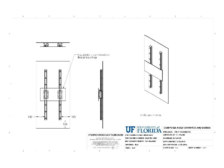
top plate 300 150 4 mm 6061 T 6 aluminum Mc. Master #6709 K 180 with guide rail suppressed base plate 400 800 5 mm 6061 T 6 aluminum Mc. Master #6709 K 63
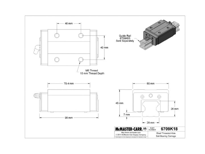

Note: To find this part at Mc. Master, select the rail part that is to the right of the ball bearing cartridge part. From that page, select the rail part that is 600 mm long.

Mc. Master #6709 K 180 with guide rail suppressed and two planes created. The assembly was easier to create with these two planes added.
 Select metric steel socket")
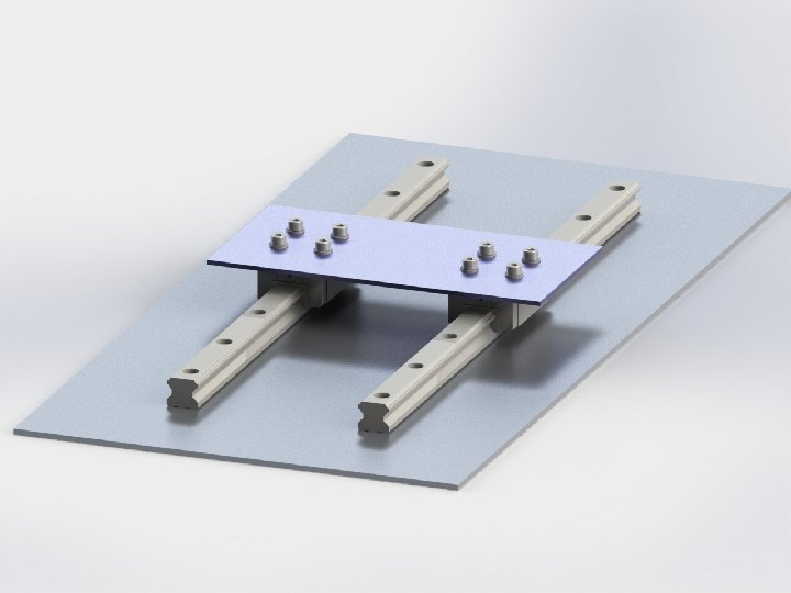
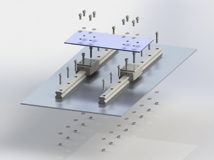
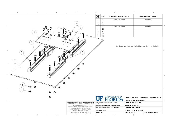
1. Attach the top plate to the linear bearings. a) Select metric steel socket cap screws and zinc-plated steel washers to attach the top plate to the linear bearings. b) Add clearance holes to the top plate. 2. Attach the rails to the base plate. a) Select metric steel socket cap screws to secure each rail to the base plate. b) Select washers and zinc plated steel hex nuts that will go underneath the bottom plate. c) Add clearance holes to the base plate. 3. Create an exploded view of your final assembly. 4. Create a drawing sheet with the exploded view of your assembly. a) Add a drawing bill of materials using the UF template. b) The part/assembly number field will include the Mc. Master part number (except for the top and base plates). c) The part/assembly name field should include the dimensions of the item, such as the thread size and length (for a screw). For example, for a screw, part/assembly number: Mc. MASTER 362 K 68 part/assembly name: CAP SCREW, M 8, 14 MM LONG 5. Turn in 3 files. a) your assembly file b) your drawing file (one sheet with the exploded view and bill of materials table) c) a zip file that contains everything (assembly file, drawing file, and part files). You may use pack-and-go.
- Slides: 10