Material Characterization Rheology Rheology is the science that


: The fluids for which the applied stress ( ) is")


 Definition: It is defined as the measurement of the")


 Ostwald Fenske Method by using Ubbelohde Test Tube Definition: It")


 9. 3. 2. 1. 1")


 Minimum Viscosity b) The")


- Slides: 52
Material Characterization
Rheology: Rheology is the science that studies the deformation and flow of materials in liquid, melt or solid form in terms of materials elasticity and viscosity. Elasticity: Elasticity is the ability of material to store deformational energy, and can be viewed simply as the capacity of material to regain its original shape after being deformed. Viscosity: Viscosity is the measure of materials resistance to flow. Viscoelasticity: Materials respond to an applied displacement or force by exhibiting either elastic or viscous behavior or a combination of these, called Viscoelasticity.
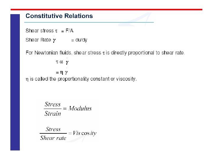
Ideal Fluids (Newtonian fluids): The fluids for which the applied stress ( ) is proportional to the strain rate or shear rate i. e. , follows Newton’s law are called Ideal fluids. Let us imagine two parallel plates of very large area A at a distance of y apart by an ideal fluid. A shear force F is applied to the top of the plate and the top plate moves with uniform velocity u. (as shown in Fig. 1). Moving plate with surface area ‘A’
The viscosity of a Newtonian fluid is dependent only on temperature but not on shear rate and time. e. g. Water, Milk, Sugar solution, Mineral Oil etc. Most cases, the relationship between shear stress ( ) and shear rate ( ) is not linear and these fluids are called Non. Newtonian Fluid. In contrast to Newtonian Fluids, these fluids show either time dependent or time independent behavior.
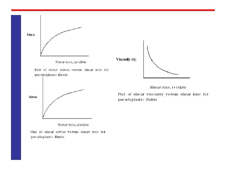
Non Newtonian Fluids, Time Independent The viscosity of a Non Newtonian time independent fluid is dependent only on temperature and shear stress ( ) and shear rate ( ) Depending on how viscosity ( ) changes with shear rate ( ) the flow behavior is characterized as Shear Thinning – the decreases with increased . Pseudoplastic Fluids Shear thinning fluids are also called pseudoplastic. e. g. Paint, Shampoo, Slurries, Polymer Melts, Ketch up, etc. The and relationship for pseudoplastic fluids is shown below
Shear Thickening – the increases with increased Dilatant Fluids Shear Thickening fluids are called dilatant. Examples are wet sand, concentrated starch suspensions, etc.
Bingham Liquids– exhibits so called yield value. i. e. a critical shear stress must be applied to cause the fluid flow. Bingham Fluids / Plastic These fluids are believed to have an internal structure, which resists the flow of fluid at lower shear stress. Therefore, a certain shear stress value needs to be applied to help the fluid flow. Examples: Tomato Paste, Tooth Paste, Hand Cream, Grease, etc.
The important type of Non Newtonian fluid is the psudoplastic one and polymer melts and rubber components behave in this way.
Melt Flow Index Test (MFI) Definition: It is defined as the measurement of the rate of extrusion of molten resin through a die of specified length & diameter under prescribed conditions of temperature and pressure in 10 min. The unit of MFI is g/10 min. Test Methods: v. ASTM D 1238 v. ISO 1133 1991
Test Apparatus: • Test Sample • Steel Cylinder • Die • Heater • Piston • Load • Thermometer • Weighing Balance
Test Sample: The test specimen should be in the form of powder, granules, strips or film or moulded slugs of Thermoplastics material Steel Cylinder: The Steel Cylinder shall be 50. 8 mm in Dia. , 162 mm in length and a straight hole 9. 5504 ± 0. 0076 mm in Dia. . It is a thermal sensor one and thermometer is provide in it. Die: The outside of the steel die shall be 9. 5504 ± 0. 0076 mm in diameter that it will fall freely to the bottom of the steel cylinder. The die shall have 2. 0955 ± 0. 0051 mm in inner Dia. And 8 ± 0. 025 mm in length. Heater: The heater must have the capacity to heating the apparatus and maintain the temperature ± 0. 2°C at 10 mm above the die.
Piston: The piston shall be made of steel with an insulating bush at the top as a barrier to restrict the heat flow from the piston to load. The land of the piston shall be 9. 4742 ± 0. 0076 mm in Dia. and 6. 35 ± 0. 13 mm in length. Load: The cylindrical steel load has different weight in size based on the material such as 0. 0. 325 kg, 1. 2 kg, 2. 16 kg, 3. 8 kg, 5. 0 kg, 12. 5 kg, 21. 6 kg, 31. 6 kg. Note: The combined weight of piston and load shall be within a tolerance of ± 0. 5% of the selected load. Weighing Balance: The weighing balance should have the capacity to measure the four decimal of weight of the sample.
Test Procedure: Place thermometer on the hold provided. The set temperature stabilizes for 5 min. than charge the material using tool without any air gap. Then apply the load over the piston. Allow some time for material to melt and soften and purge the material up to the lower mark of the piston. Then start the stopwatch and start cutting off the extrudate depending upon the flow. Calculations: 30 Sec. , 1 min, 3 min, or 6 min intervals and tabulate the weight of the extrudate. Flow rate = (m/t) x 600 Where m = mass of extruded, t = time of piston travel for length L. (sec), 600 = conversion factor to convert in sec.
9. 3. 2. 1. 1. 9 Factors Influencing: 1. Preheat Time. If the cylinder is not preheated for a specified length of time. This causes the flow rate to vary considerably. 2. Moisture in the material, especially a highly pigmented one, causes bubbles to appear in the extrudate. The weight of the extrudate is significantly influenced by the presence of the moisture bubbles. 3. Packing. The sample resin in the cylinder must be packed properly by Pushing the rod with substantial force to allow the air entrapped between the resins Pellets to escape. Once the piston is lowered, the cylinder is sealed of air can escape. This causes variation in the test results. 4. Volume of Sample. In order to achieve the same response curve. Repeatedly, the volume of the sample in the cylinder must be kept constant. Any change in sample volume causes the heat input from the cylinder to the material significantly
Summary of test specimen for MFI
Dilute Solution Viscosity
Dilute Solution Viscosity (DSV) Ostwald Fenske Method by using Ubbelohde Test Tube Definition: It is defined as the measurement of viscosity of the dilute solution of polymer. This gives the correlation between dilute solution viscosity and molecular weight or chain length. Test Methods: v. ASTM D 2857 95(2007) v. ISO 1628
Test Apparatus: • Volumetric Flask • Transfer Pipet • Constant Temperature Bath • Viscometer • Stopwatch • Thermometer
Procedure: v This method is applicable to all polymers that dissolve completely without any chemical reaction with the solvent or degradation to form solutions that are stable with time at a temperature between ambient and 150°C. v Weigh an appropriate sample into a volumetric flask and then add 50 cm³ of solvent and shake it. v A suitable quantity of the solution is transferred into the U tube viscometer by using transfer pipette. The test temperature is maintained in a constant temperature bath. v After temperature achieved their set temperature, the liquid level of viscometer is brought above the upper graduation mark in the bulb A by means of gentle air pressure. Then allow the solution to drain down through the capillary. v The efflux time (t) is measured between the two marked points using a timer. The efflux time for solvent (t 0) is also measured under similar conditions. In order to measure the intrinsic viscosity, solutions of different concentration are used.
v. The presence of small amount of a polymeric material dissolved in a solvent significantly increases viscosity of the solvent. Such an increase in viscosity is dependent on the concentration and molecular weight of the polymer and its interaction with solvent v. In order to determine the molecular weight of a polymer, viscosity of polymer solutions at different concentrations relative to that of the solvent is measured. v. Since only relative measurements are required, capillary viscometers are well suited. The most convenient viscometers are Ostwald viscometer and Ubbelohde viscometer.
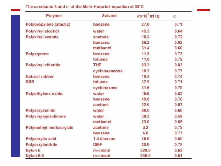
v The viscosity of dilute polymer solutions may be related to the molecular weight of the polymer. This method involves the measurements of viscosity of dilute polymer solutions over a concentration range (usually up to 2 g dl 1). The polymer is usually separated into narrow molecular weight distribution fractions, which are characterized by absolute molecular weight methods. The molecular weight is related to the intrinsic viscosity by the Mark Houwink relationship. v The molecular weight is related to the intrinsic viscosity by the Mark Houwink relationship. v Where k and are empirical constants and are characteristic for a polymer solvent pair at a given temperature.
Huggins Equation Kraemer Equation
Definition of Different viscosity terms: Relative Viscosity, rel: It is the ratio between the solution viscosity ( ) to the solvent viscosity ( o). Specific Viscosity, sp: It is related to the fluid viscosity increase due to all polymer solute molecules. Reduced Viscosity: The ratio of the relative viscosity increment to the mass concentration of the polymer
inherent Viscosity inh: The ratio of natural logarithm of the relative viscosity to the mass concentration of the polymer Intrinsic Viscosity, : The limiting value of the reduced viscosity or the inherent viscosity as the polymer solute concentration approaches zero.
Significance: v It is giving the information about the molecular characterization of polymers. v Viscosity is dependent on molecular weight distribution. So we can determine the molecular weight and chain length of polymers. v It is used to differentiate the polymer grades based on the molecular weight distribution. Limitations: v The polymer type, molecular weight and its distribution will affect the flow time. v Concentration of the solution and air bubbles present in the solution will also affect the flow time and viscosity. v Temperature is also affect the viscosity of the solution. v Dilute solution viscosity data are dependent upon the purity of the ingredients in solution and type of viscometer. So at the beginning of each experiment, the viscometer to be washed with acetone.
9. 3. 1. 2. 5 Brookfield Viscometer 9. 3. 1. 2. 5. 1 Definition: The viscosity defines the flow behaviour of plastisol under low shear. This viscosity relates to the conditions encountered in pouring, casting, molding and dipping process. The Brookfield instrument is a commercially used rotating spindle type viscometer. 9. 3. 1. 2. 5. 2 Significance: The suitability of a dispersion resin for given application process is dependent upon its viscosity characteristics. The test standard for viscosity measurement of plastisols / organosols, epoxy resin and emulsion etc. 9. 3. 1. 2. 5. 3 Test Methods: ASTM D 2393, ASTM D 1824 and ISO 2555.
9. 3. 1. 2. 5. 6 Procedure: 1. Select the spindle in middle or upper portion of viscometer dial at the highest rotational speed to be used. Insert the spindle approximately at 45° angle. Move the sample so as to center the spindle, adjust the depth to the immersion mark. 2. Start the viscometer at its lowest speed. Allow it to run 2 min. record the scale reading during the next rotation. 3. Placing it in a constant temperature bath at the specified test temperature preconditions the sample. The proper size spindle is allowed to rotate in the sample for 30 sec. The instrument is stopped through the use of a clutch and the reading is taken from the dial. The test is repeated until a constant reading is obtained. Record the sample temperature at the conclusion of viscosity reading.
Conversion table from centipoises to factor
9. 3. 1. 4 Dilute Solution Viscosity & K Value 9. 3. 1. 4. 1 Ostwald Fenske Method 9. 3. 1. 4. 2 Ubbelohde 9. 3. 1. 4. 2. 1 Definition: Inherent Viscosity, inh: The ratio of natural logarithm of the relative viscosity to the mass concentration of the polymer; c: inh =(In r)/c. Intrinsic Viscosity [ ]: The limiting value of the reduced viscosity or inherent viscosity at infinite dilution of the polymer Reduced Viscosity: The ratio of the relative viscosity increment to the mass concentration of the polymer i. e. Relative Viscosity: The ratio of the difference between the viscosities of solution and solvent to the viscosity of the solvent i. e.
9. 3. 1. 4. 2. 2 Significance: # Measuring the viscosity of dilute solutions prepared in suitable solvents can be useful for understanding the relative molecular characteristics of polymers. When viscosity data are used in conjugation with other molecular parameters, the properties of polymers pending on their molecular structure can be better predicted. It is also possible to obtain a satisfactory correlation between dilute solution viscosity and molecular parameters such Molecular weight or chain length of linear polymers. # The viscosity (kinetic) determination of dilute solutions involves the use of all efflux viscometer having a capillary bore or small orifice that drains by gravity. The values strongly dependent on density or specific gravity of the liquid, and is measured in stocks (S) and centistocks (c. S). The value in poise is obtained on multiplication of measured value with specific gravity.
The viscosity of dilute polymer solutions may be related to the molecular weight of the polymer. This method involves the measurements of viscosity of dilute polymer solutions over a concentration range (usually up to 2 g dl 1). The polymer is usually separated into narrow molecular weight distribution fractions, which are characterized by absolute molecular weight methods. The molecular weight is related to the intrinsic viscosity by the Mark Houwink relationship. Where k and are empirical constants and are characteristic for a polymer solvent pair at a given temperature.
9. 3. 1. 4. 2. 3 Procedure: # A suitable quantity of the solution is transferred into the viscometer suing transfer pipette. The test temperature is maintained in a constant temperature bath. # The liquid level of viscometer is brought above the upper graduation mark in the bulb A by means of gentle air pressure. # The efflux time (t) is measured between the two marked points using a timer. The efflux time for solvent (t 0) is also measured under similar conditions. In order to measure the intrinsic viscosity, solutions of different concentration are used. # The presence of small amount of a polymeric material dissolved in a solvent significantly increases viscosity of the solvent. Such an increase in viscosity is dependent on the concentration and molecular weight of the polymer and its interaction with solvent
# In order to determine the molecular weight of a polymer, viscosity of polymer solutions at different concentrations relative to that of the solvent is measured. # Since only relative measurements are required, capillary viscometers are well suited. The most convenient viscometers are Ostwald viscometer and Ubbelohde viscometer. Definition of Different viscosity terms
Huggins Equation Kraemer Equation
9. 3. 2 Flow Properties of Thermosetting Materials Factor Affecting Flow: 1. Resin Type: All resin flow differently because of basic differences in the structure of the polymer e. g. melamine formaldehyde exhibit longer flow than urea formaldehyde. 2. Type of filler: The small particle size filler e. g. wood floor, mica, and minerals creates less turbulence and less frictional drag during mold filling. The size of the glass fibre and long fibre can adversely affect the flow. 3. Storage Time: All resins have a natural tendency to polymerize in storage, causing partial precure, which reduces flow.
9. 3. 2. 1 Cup Flow (ASTM D 731) 9. 3. 2. 1. 1 Definition: The measurement of the molding index of thermosetting plastics ranging in flow from soft to stiff by selection of appropriate molding pressure within the range from 4. 1 to 31. 9 MPa 9. 3. 2. 1. 2 Significance: This test is specifically designed for thermosetting molding compounds. This test is primarily useful for determining the minimum pressure required to mold a standard cup and the time required to close the mold fully. The material is molded using a mould of specified cup shaped cavity dimensions. The method provides the guide for evaluating the mold ability of thermosetting powders. 9. 3. 2. 1. 3 Test Methods: ASTM D 731
9. 3. 2. 1. 6 Test Apparatus: The test apparatus shown in Figure
9. 3. 2. 1. 7 Procedure: 1. The rate of flow is sensitive to the condition of the mold surface. First two reading has to be discarded and after two successive reading the mold flow can be accepted. The preferred mold temperature is given below: Phenolics: 165 1 °C Melamine: 155 1 °C Urea: 150 1 °C Epoxy: 150 1 °C Diallyl phthalates: 150 1 °C Alkyd: 150 1 °C
# Take the weight and begin the test with proper load to close the mold to the fin thickness specified for the type of material. The load can be applied to the mold is as given below: Total Load Molding Pressure (MPa) 1112 4. 6 1601 6. 6 1124 9. 0 1686 13. 6 2248 18. 0 3372 21. 2 4496 36. 3 11120 45. 4
# If a 2248 N load applied to make initial cup and required fin thickness is obtained, the next lower load 1686 N is applied as indicated above. If the mold close to the required thickness again then next 1124 N load applied. If the mold then does not close, the ‘molding index’ is close to 1686 N load. # The time of flow in seconds shell be measured from that the hydraulic gage indicates an applied load of 454 kg to the instant that the fin has reached 0. 20 mm I thickness for material with an izod impact strength of 27 J/m of notch.
9. 3. 2. 2 Spiral Flow 9. 3. 2. 2. 1 Definition: The spiral flow of a thermosetting molding compounds is a measure of the combined characteristics of fusion under pressure, melt viscosity and gelation rate under specific condition. 9. 3. 2. 2. 2 Significance: This is a high shear rate test for thermoplastics and is widely accepted in the molding industry and quality control test. The test is performed on an injection molding machine under specified condition and using a spiral flow mould. 9. 3. 2. 2. 3 Test Method: ASTM D 3123 98
9. 3. 2. 2. 4 Procedure Molding condition: 1. Temperature: A temperature of 150 3°C shall be maintained on the mold and transfer plunger. 2. Transfer Pressure: The actual pressure applied to the compounds at the base of the pot shall be 6. 90 0. 17 MPa. 3. Charges Mass: The mass of the compounds shall be determined empirically so that the thickness of the molded compounded on the top of the sprue plate of the mold. 4. Transfer plunger speed: The transfer plunger speed without load shall be controlled between 25 and 100 mm/s. 5. Pressure Cure Time: sufficient cure time shall be used to facilitate easy removal of spiral from the mold.
Spiral flow data of polypropylene. 9. 3. 2. 3 Disc Flow Test
9. 3. 3 For Elastomer For vulcanisable compound a measure of the time to the incipient vulcanisation and rate of curing can be determined for elastomeric material using Mooney viscosity. 9. 3. 3. 1 Mooney Viscosity 9. 3. 3. 1. 1 Definition: Mooney viscosity is defined as the shearing torque resisting rotation of a cylindrical metal disk (or rotor) embedded in rubber within a cylindrical cavity. 9. 3. 3. 1. 3 Test Method: ASTM D 1646, ISO 289
9. 3. 3. 1. 2 Significance: 1. By this method molecular mass and viscosity can be determined because rubber is non newtonian fluid. 2. These mooney viscosities of polymers will normally relate to how they will be processed. Lower Mooney viscosity materials (30 to 50) will be used in injection molding, while higher Mooney products (60 to 80) can be more highly extended and used in extrusion and compression molding. 3. The onset for vulcanization can be detected by increase in viscosity. The curing rate also can be detected for rubbers. 4. Test Apparatus:
9. 3. 3. 1. 6 Procedure: 1. Select the rotor to be used and select the test temperature table given below: 1. Adjust the torque indicator to the zero reading while viscometer running in the unloaded condition with the rotor in place. 2. Remove the hot rotor and place the test piece and replace the viscometer and start the viscometer and recorder.
Case Study: Following can be obtained from the recorder a) Minimum Viscosity b) The time required for a specified increase above the minimum viscosity. c) Cure Index: Typical curing characteristics curve using large rotor
Scorch assessed by plasticity test on rubber sample when sample heated an increase in stiffness with heating time was observed (The results shown in Fig. ). Rate of cure is still assessed by vulcanising samples for various times and following the change in tensile properties, hardness, set, swelling etc Determinations of scorch and cure characteristics
Thank You Very Much for Your Kind Attention