Master Copy for IRTMTCALD COMPUTER WORKING SYSTEM CWS


 CWS DISPLAY")
 8 Digital inputs Microcontroller 8")


 is a subsystem of")
 Average")


 are provided to influence the ramp times for")
")
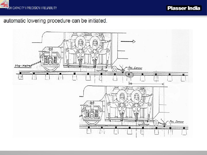
 SAT moving backward in")
")

![Working on uphill sections: The [+/-] keys on the main page allow the output](https://slidetodoc.com/presentation_image_h/13a7300e90300a75057e6487dadcee38/image-38.jpg "Working on uphill sections: The [+/-] keys on the main page allow the output")
 Relative speed (SAT/machine) measured proportional current temperature on the")


- Slides: 49
Master Copy for IRTMTC/ALD
COMPUTER WORKING SYSTEM - CWS
Introduction The abbreviation CWS means Computer Working System. Similar to the CMS system (Computer Measuring System) which has been in use for quite some time. 3
• CWS is a digitalised method of processing data which are received from various inputs. • The output of it is used to control a valve for the designated operation. • It is also used for indication purpose. • CWS also displays real time track parameter data so that actual correction done can be evaluated. • It also displays any faults occurring in its system (Diagnose).
This system consists of EK micro-controller cards and adapter cards for inputs and outputs. The same type of display and input terminal is used as for the CMS system. 5
The settings and adjustements of tamping units and squeeze pressure are made on controller cards. 6
For hydrostatic driving, among other things while driving, a driving controller is available. This can control up to four driving pumps. The card can also take over the automotive control. 7
8
For the satellites, with hydrostatic drive, there is also a separate controller available. The adaper card will not only process the hydraulic signals, but also the position and speed of the satellite. 9
© 2018 PMC Rail International Academy 10
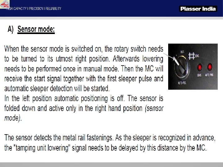
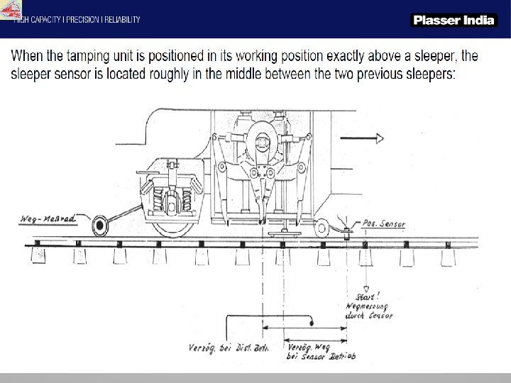
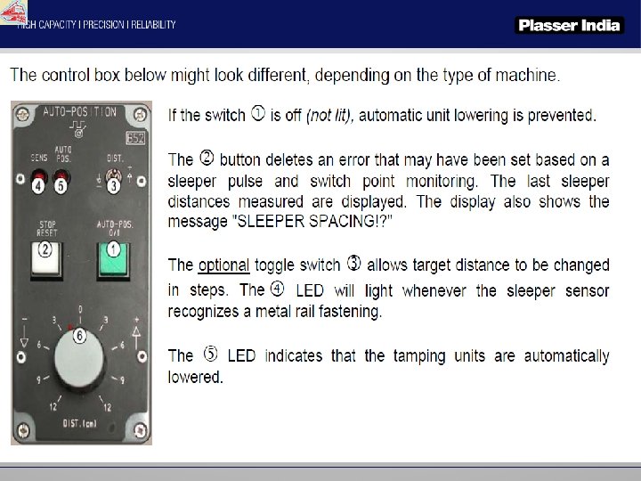
For automatic tamping a controller is availlable. The controller evaluates both the stuffing for the way, as well as the evaluation of the small iron. © 2018 PMC Rail International Academy 11
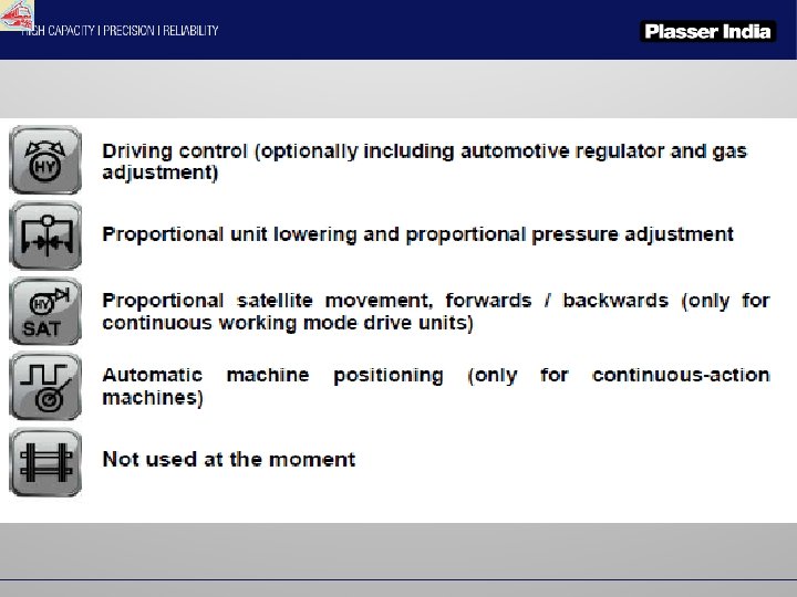
The status of the indiviual functions or their settings can be accessed via the display. The individual functions selected through the ‚F‘ keys. are As with the CMS-System you can switch to the submenu via the ‚go on‘ keys. © 2018 PMC Rail International Academy 12
DRIVING CONTROLLER PROP. TAMPING CONTROLLER PROP. LOWER 1 ST UNIT GROUP (FRONT) CWS DISPLAY PROP. LOWER 2 ND UNIT GROUP (REAR) PROP. VALVE SATELLITE AUTOMATIC POSITION SATELLITE
8 analogue outputs 8 analogue inputs Adapter (Power Board) 8 Digital inputs Microcontroller 8 Digital outputs Power output to prop. valves Analogue inputs from transducers.
Adapters • The CWS consist of five analogue adapter boards. • Equipped with 16 high-resistivity analogue inputs. • Analogue inputs include measuring equipment (Transducers), input potentiometers, correction value potentiometers. • Allow the input signals to be amplified to guarantee the best possible use of the ± 10 V. • The processed data from microcontroller is again converted to analog signals & then used to control various associated valves. • The outputs are led via buffer amplifiers on the adapter board so as to minimize radio interference. • Conversion of the output voltage of the MC card into the corresponding impressed current is also performed on the adapter card (9 V are converted to 60 m. A).
Microcontrollers • The MC board is identical with the one used in the CMS system (with 14 bit DA converter). • The microcontroller has both ADC & DAC. • The CWS consist of five digital microcontroller boards for each. • Contains the software which are decisive for entire process. • Equipped with 8 analogue outputs. • The processor used works at 40 Mhz. • All MC's are connected to the control terminal and to one another via a CAN bus.
PLASSER & THEURER CWS WORKING SYSTEM Driving mode controller or ‘F’ controller
• The driving mode controller (F controller for short) is a subsystem of CWS system. It consists of an adapter card for preparing the analogue inputs and outputs and a micro controller board. • This subsystem allows a total no. of 4 pump servo valves for hydromatic transit drive with 60 m. A converter modules. Max. voltage +9 V of MC is converted to 60 m. A. • As an alternative the max. voltage +9 V is amplified to +10 V which is used for proportion driving. • A further function of the driving controller is to provide up to 7 speed limit signals. A separate MC module (frequency - voltage converter) calculates the machine running speed from a speedometer signal and read in via an analogue input of the CWS system (+10 V = 140 km/h). The speed limits can be set individually and are outputted in binary codes on 3 digital outputs. • An external MC module calculates the engine speed and transmits it to the CWS driving controller (+10 V=2500 rpm).
F Controller operation via terminal: Current working speed (Input - distance measuring wheel) Average working speed Press the “service" key to shift to the detailed display. The button shows yellow when detailed view is active. 1. Driving mode symbol (working mode drive) Driving enabling Forward / backward driving Main Engine Speed Input % of the selected accelerator Tamping depth (Manual input) Additional engine speed
The detailed display shows all the relevant inputs and outputs: Driving enabling Operational mode Speed (transiting: machine speed, otherwise working speed) Main engine RPM Additional engine RPM Special mode 1 (for example, sweeping) Special mode 2 (additional engine) output to servo pump 4 (± 100% = ± 9 V = 60 m. A) Additional engine RPM Full throttle signal % acceleration of selected mode Special input 1 or 3 enabled driving-mode output influencing by comparison of pressure values (± 10%)
Options for adjustment and calibration in the service menu • Each microcontroller has its own Service Menu. • This is called up by pressing the Service button. This is indicated by a brief buzzer sound. • The work function of the MC is switched off when the service menu is open. The RUN LED is switched off. • When the service menu is closed, a short buzzer sounds briefly again and the F Controller returns to working mode. The RUN LED is now illuminated. 1. General settings (servo pump assignment, etc. ) 2. Calibration: Adjustment of the zero offset and scaling factors. 3. Diagnostics: Display of digital and analogue inputs and simulation of outputs.
• Adjustments and calibrations as well as diagnostics can be carried out only when the “Drive permission” signal is switched off. All settings and calibration values are stored in an EEPROM on the MC card. To be able to change values, the write-protection switch must be set to the ‘ENA’ position. Once all adjustments have been made, the switch should be returned to the ‘DIS’ position for safety reasons.
1. General settings As soon as the MC is ready, a green tick is shown in the bottom left corner of the display.
• • • The output pump assignment and a maximum control level can be set for each drive. Specify which output voltage is to be output for 100% transducer deflection. The default value is +9 V. This is converted by the adapter card to 60 m. A for the servo control level. If, for example, the control level is set to 90%, only 90% of 9 V are output at 100% transducer deflection. Each servo output can be set separately during assignment. An assignment of, e. g. 1010, means that outputs 1 and 3 are triggered in this mode.
Continue button • Furthermore, there are 2 special inputs available (FA 18 and FA 24). These can be used e. g. for a brush speed or DTS vibration or an additional engine (FA 24). Only one pump output each is possible when assigning these inputs.
PLASSER & THEURER CWS WORKING SYSTEM Proportional pressure controller or ‘PD’ controller
• The PD controller consists of an adapter power board and a micro-controller board containing the software. • Like in the CMS system, all MC's are connected to the control terminal and to one another via a CAN bus. • 2 proportional power stages are fitted on the adapter board to directly control two pressure proportioning valves that are pre-charged with a pressure of approximately 80 bar by a reducing valve. The voltage of the MC output amounting to between 0 and +9 V is converted to max. 680 m. A which corresponds to a pressure increase by approximately 70 bar. As the pressure system is pre-charged with a pressure of 80 bar, this leads to a maximum pressure of about 150 bar. • A measurement circuit converts the currently available proportional current into a proportional voltage (680 m. A = approx. +6. 8 V) which is then returned to the MC where the actual current value is displayed in the detailed view of the display (100% at a control voltage of +9 V). • Another output of the adapter board allows the heat sink temperature to be measured.
PD Controller operation via terminal: Working speed – measured with the distance measuring wheel external modification of the common pressure value. Current pressure values A/B Current pressure values C/D Standard tamping pressures for the units A/B (if different pressure values are applied) Modification of the pre-set unit lowering speed by touching a button Lifting positions target tamping depth
This detailed view also displays the details of the proportional-lowering board Adapter board number (1=A/B, 2=C/D, 3=E/F) Position of tamping unit. Temperature from the proportional-pressure power adapter board. Proportional current / pressure valve (B) Current proportionalcontrol current and tamping pressure (A) Pressure reduction (A) pressure increase (B)
PLASSER & THEURER CWS WORKING SYSTEM Satellite controller
• The MC board supplies the adapter board with a voltage between 0 and +9 V to control the hydraulic motor flow volume (SAT forward / backward movement); this voltage is there converted into the corresponding current (max. 1. 1 or 1. 5 A). This corresponds to a signal amplitude between 0 and 100%. A beat frequency of approx. 200 - 270 Hz is produced by the hardware on the adapter card (can be adjusted with a potentiometer) and superimposed on the main signal to improve response and resolution. The stepchange to the bias current (flow > 0) or the maximum required range is determined by the MC signal. A relay in the power part of the adapter board serves to switch between the directions of movement; this relay is also controlled by the MC board. • The SAT position value is also led via the adapter board where it can be amplified, if necessary. A maximum voltage of +9. 2 V should be supplied to the MC input in the rear, locked position.
• Two potentiometers (min/max=0 -100%) are provided to influence the ramp times for acceleration and the pressure relief valve for braking. This allows the skidding tendency of the satellite on wet rails to be reduced. When the brake potentiometer is turned towards the minimum value, this will bring forward the point of braking. This can also be used to prevent the satellite from swinging beyond the front zero point. • The maximum satellite speed (volume) can be set on line in 5 stages on the display (5=fastest stage). Instead of this an external 5 -stage potentiometer can be connected that is fitted in an easy-to-reach position in the arm rest.
SAT Controller operation via terminal Machine Working speed SAT position (0 mm=locked at rear) SAT speed stages Lowering position, adjustable driving mode Proportional current Enhancement of SAT control on uphill sections (0=level track) SAT mode External correction potentiometers (acceleration / braking, 100% = standard values, 0% = smoother)
SAT modes: SAT home position automatic mode (SAT forward movement) SAT moving backward in manual mode SAT moving forward in manual mode
Driving modes: machine at a standstill accelerator pressed SAT locked at rear (sleeper/sleeper mode) machine driving backward
Before the SAT mode is activated for acceleration purposes, a "preparation" signal can be created. An hourglass will be displayed. This signal uses 90% of the calibrated bias current (110% for Gold Cup), thus leading to a faster response in the subsequent acceleration. The following icon indicates the digital input SA 32 (20 d) of the SAT engaging aid.
Working on uphill sections: The [+/-] keys on the main page allow the output voltage to be changed when the front point is reached. Such an increase may become necessary when the machine works on uphill sections. The values [0. . 5] are displayed, 5 being the highest gradient. Press the "reset" button to restore the standard stage "0". Acceleration and braking potentiometers: These potentiometers that were mentioned before (min/max) are provided for influencing the acceleration and braking procedures. The acceleration potentiometer influences the following parameters: a) Ramping time for the pump flow b) Ramping time for SAT cylinder control c) If a Gold Cup pump is used, flow pressure limitation is also influenced. The ‚max’ position (display = 100%) indicates the greatest acceleration. The braking potentiometer only has the effect of reducing the pressure limit in the return line (reduced braking effect, for example, on wet rails). This also increases the brake ramp distance in order to compensate the weaker effect.
SAT position actual value (0=rear) Relative speed (SAT/machine) measured proportional current temperature on the adapter card digital inputs external potentiometer (min/max = 0… 100%) Maximum pressure valve value, taking into account the external potentiometers (100% = 10 V). Acceleration times, taking into consideration the external potentiometers
Advantages • User friendly • The present model is android based and fully touch screen system. • The credibility of this system is very high. • Previous analog plates where prone to problem due large number of potentiometers used. • CWS system indicates to stop work if any input or any measuring device fails. Track is not disturbed. It also indicates which input is malfunctioning.
THANKS. . . !!