Massive Gas Injector Power supply and control system

 Overview • Supply schematic – Relays and interlocks")


- Slides: 26
Massive Gas Injector Power supply and control system CDR 10/16/2015
Outline • Massive Gas Injector (MGI) Overview • Supply schematic – Relays and interlocks – Control signals – High voltage considerations • Control system – NI c. RIO chassis and modules – Power – Modules: DO, DI, AO, AI – Sequence and state diagrams • System tests • Other necessities – NEPA, Vacuum PLC, PCS, etc. • Timeline
MGI Overview • Unmitigated disruptions in a tokamak discharge – Cause excessive diverter heat loads – Large halo currents • Injecting massive amounts of gas prior to the disruption can thermally quench the plasma and reduce the impact of disruptions – NSTX-U is studying the effects of MGI at various poloidal locations around the plasma – The injectors are installed; Power supplies and control systems are presented here
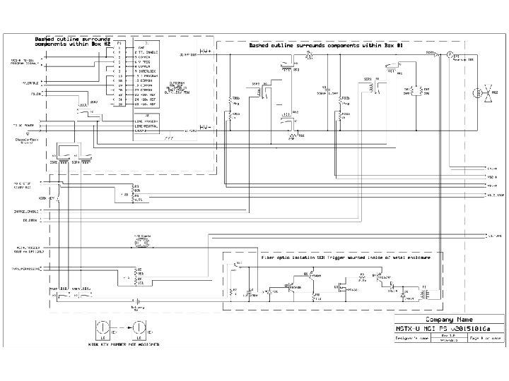
Supply Schematic I • High Voltage Ross Relays control the connections to the dump resistor (RR 1) and Glassman charging supply (RR 2, RR 3) • Solid State Relays – SSR 1 controls operation of RR 1; SSR 2 controls RR 2 and RR 3 – SSR 3 controls power to Glassman supply – SSR 4 and SSR 5 allows TVPS (24 VDC) to inhibit power to the charging supply, RR 1, RR 2, and RR 3 – SSR 6 and SSR 7 allows NO-E-STOP (120 VAC) to inhibit power to the charging supply, RR 1, RR 2, and RR 3 – Kirk key interlock is in series with NO-E-STOP • Kirk keys lock the boxes shut. The supply is inside these boxes • Normal operation – SSR 1, SSR 2, and SSR 3 are controlled by NI c. RIO Control System – SSR 4, SSR 5, SSR 6, and SSR 7 are controlled by NO-E-STOP, TVPS and Kirk Key – Loop Set/H. I. S. is monitored by NI c. RIO Control System (discussed later)
Supply Schematic II • Control signals – Everything is coming from the NI c. RIO system – Digital: DR_OPEN, CHARGE_ENABLE, PC_ON, HV_ENABLE – Analog: VC 1 • Several signals are continuously monitored, typically through voltage dividers – VD_E_STOP, VD_TVPS, LOOP_SET (discussed later) to monitor permissives – VD 1, VD 2 to monitor supply and capacitor voltage – CM 1 to monitor current out to MGI solenoid • High Voltage – Suggested: Capacitor (-) is connected to chassis ground at all times – As built: Capacitor (-) is connected to 250 Ohm which is connected to ground through the Glassman power supply – The device that triggers the SCR is battery-powered, electrically isolated (via fiber optic) from the rest of the system and isolated by a transformer from the SCR – System has been tested for functionality and high-potted to 2. 5 k. V
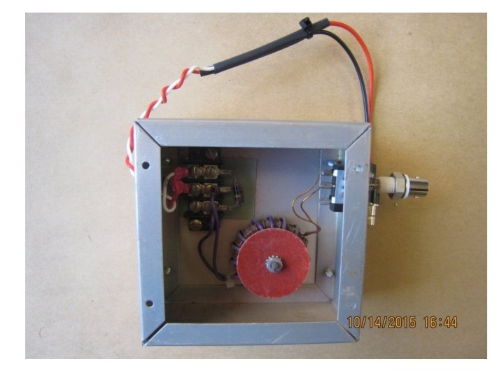
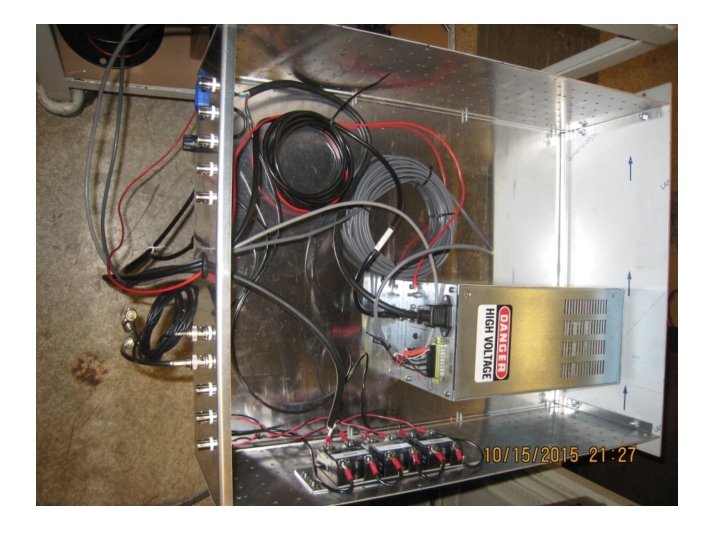
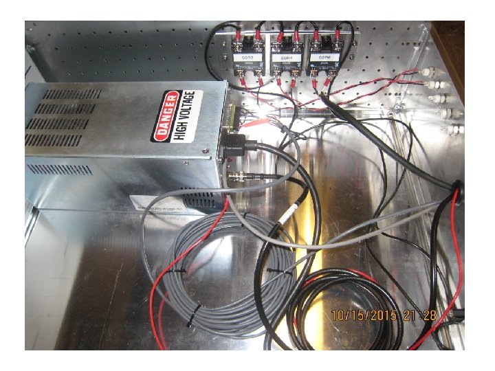
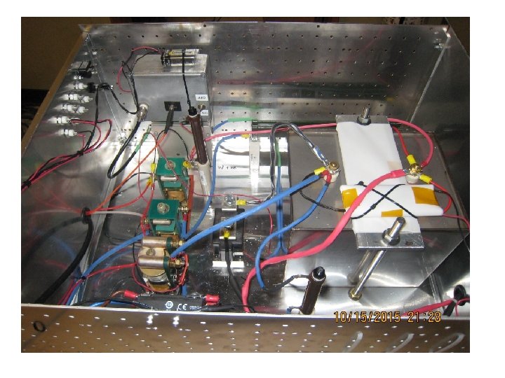
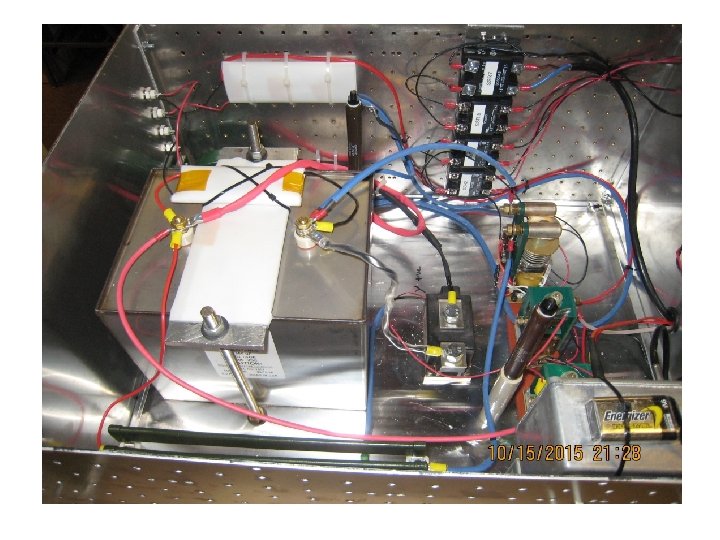
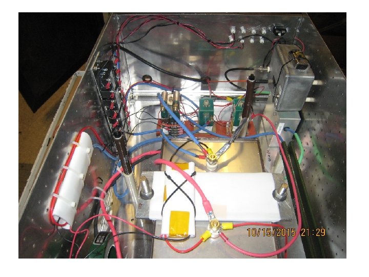
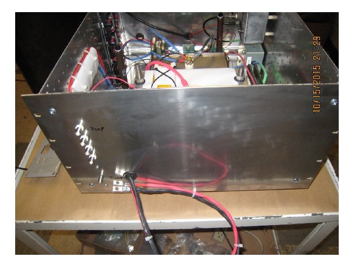
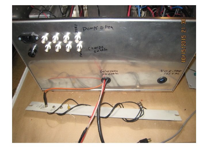
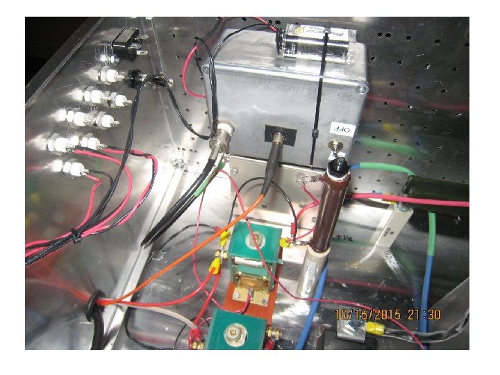
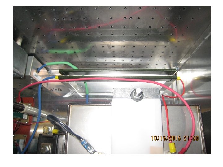
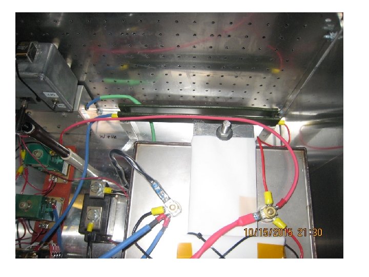
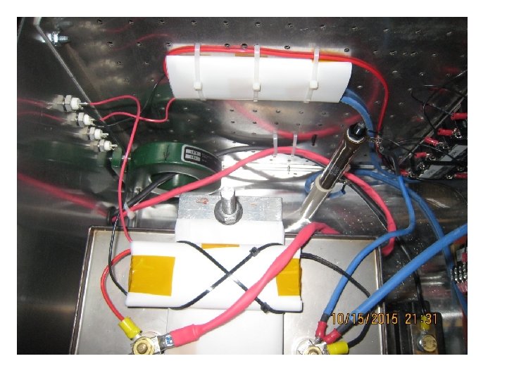
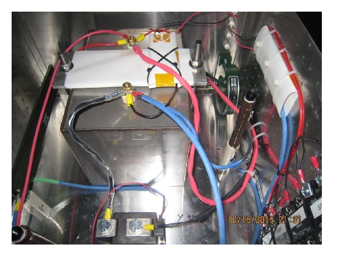
Supply Schematic III • Cost Estimate – I don’t have costs for all ‘big ticket’ items • Glassman power supply, Ross Relays, Enclosure – Around $500 -$600 total for rest • Prototype is under construction at U-Wash – Photographs are on the next slides
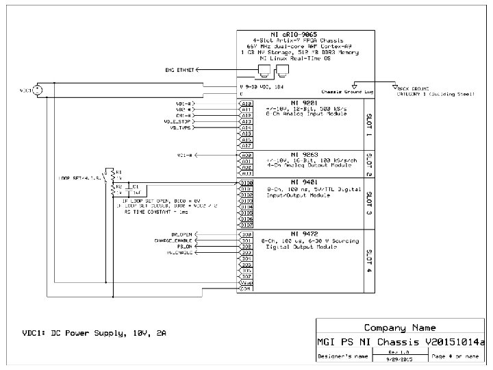
NI c. RIO Control System I • Chassis: Compact. RIO-9065 – – – 4 -Slot Artix-7 FPGA 667 MHz dual-core ARM Cortex-A 0 1 GB NV Storage, 512 MG DDR 3 Memory NI Linux Real-Time OS Ethernet • Modules – – NI 9201: 8 -ch Analog Input, ± 10 V, 12 -Bit 500 k. S/s NI 9263: 4 -ch Analog Output, ± 10 V, 16 -Bit, 100 k. S/s/ch NI 9401: 8 -Ch, 100 ns, 5 V/TTL Digital I/O Module NI 9472: 8 -Ch, 100 us, 6 -30 V Sourcing DO Module • Power – Chassis and DO Module require external power supply • 10 V, 2 A ‘brick’ style supply, plugged into a power strip located in rack would suffice • NI Quote: $4419
NI c. RIO Control System II • State Diagram – See attachment • Software issues – Using existing NI software license (Labview, FPGA and Realtime): FREE, but with risks • I have never had ‘official’ NI LV training; Software may not be optimal • Paul S and I would be ‘sharing’ the license – Upgrading to the newest ‘embedded’ suite software: $5700 • Still time sharing the license, no training – New embedded suite with online training: $9900 • Two complete software setups • Access to online training – go at my own pace • Software would more likely be optimal – Just training (1 -year, unlimited classroom and virtual, not online): $6210 • Still time sharing license, no online training, may have to travel to classroom – Just the bare minimum courses, classroom training (off-campus) • Core 1 and Core 2 - $4000 • Embedded Control and Monitoring - $3210
System Tests • Power inhibit tests – No_E_stop, TVPS_Permissive, Kirk Key • • • High-pot/isolation tests Software E stop Power on/No SCR trigger Vcap > 1. 05 x Vrequest Basic Timing/Functional • This list needs to be formalized
Other necessities • NEPA form - done • Vacuum PLC – Will need TVPS permissive to racks • PCS – Will need trigger signal to racks • NO-E-STOP, Loop set / H. I. S. signals to racks • Kirk Keys • Others?
Timeline • • • MGI Power supply: Mid-December Control system: Early December Install Electrical system HW: Mid-December Test supply into dummy load: Early January Test supply into MGI valve: Early January