
Mass Spectroscopy Alireza Ghassempour Ph D Medicinal Plants




- Slides: 81
Mass Spectroscopy Alireza Ghassempour (Ph. D) Medicinal Plants and Drugs Research Institute Shahid Beheshti University Evin, Tehran
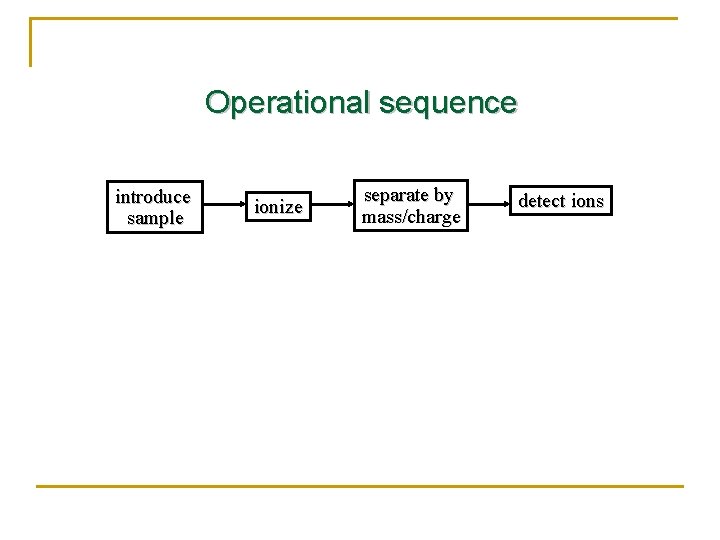
Operational sequence introduce sample ionize separate by mass/charge detect ions
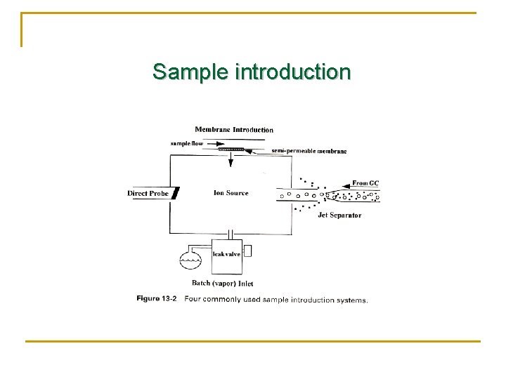
Sample introduction
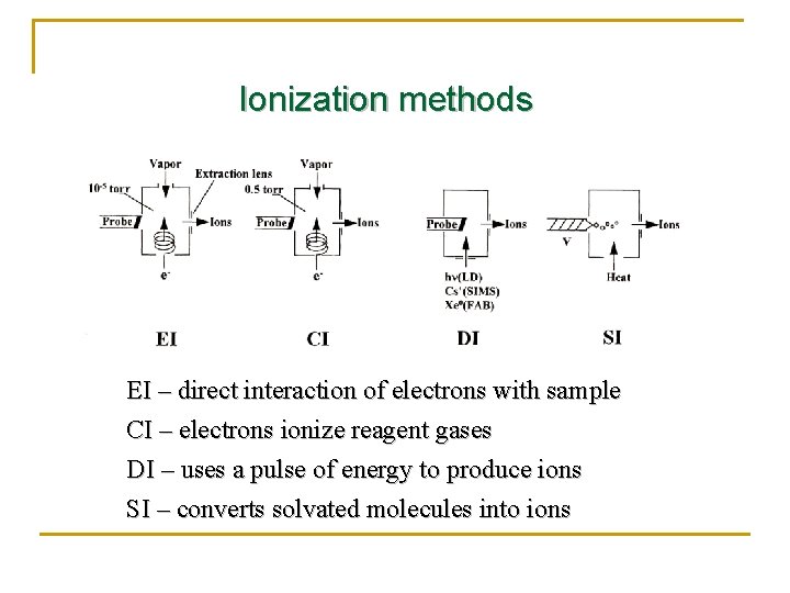
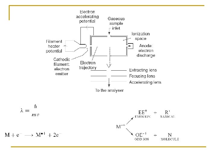
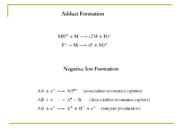
Ionization methods EI – direct interaction of electrons with sample CI – electrons ionize reagent gases DI – uses a pulse of energy to produce ions SI – converts solvated molecules into ions
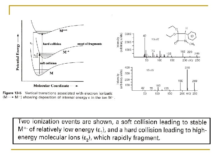
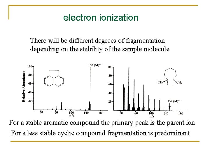
electron ionization There will be different degrees of fragmentation depending on the stability of the sample molecule For a stable aromatic compound the primary peak is the parent ion For a less stable cyclic compound fragmentation is predominant
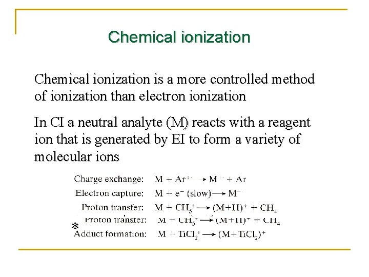
Chemical ionization is a more controlled method of ionization than electron ionization In CI a neutral analyte (M) reacts with a reagent ion that is generated by EI to form a variety of molecular ions *
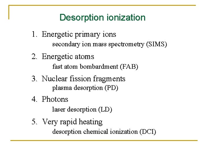
Desorption ionization 1. Energetic primary ions secondary ion mass spectrometry (SIMS) 2. Energetic atoms fast atom bombardment (FAB) 3. Nuclear fission fragments plasma desorption (PD) 4. Photons laser desorption (LD) 5. Very rapid heating desorption chemical ionization (DCI)
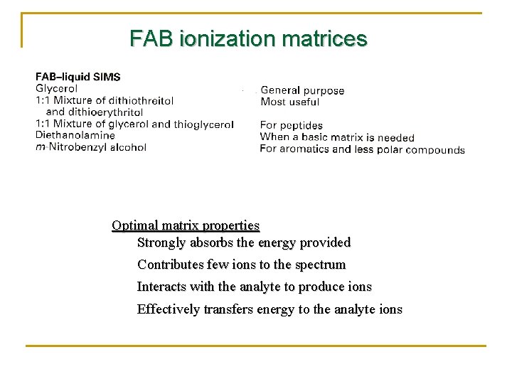
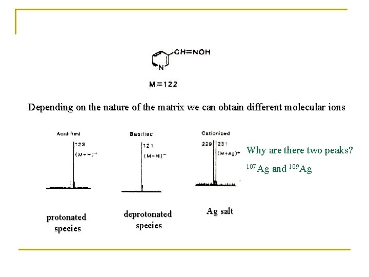
FAB ionization matrices Optimal matrix properties Strongly absorbs the energy provided Contributes few ions to the spectrum Interacts with the analyte to produce ions Effectively transfers energy to the analyte ions
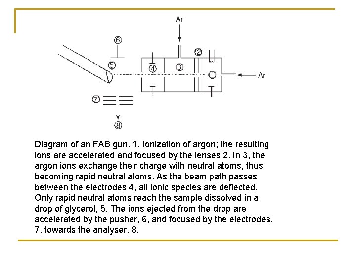
Diagram of an FAB gun. 1, Ionization of argon; the resulting ions are accelerated and focused by the lenses 2. In 3, the argon ions exchange their charge with neutral atoms, thus becoming rapid neutral atoms. As the beam path passes between the electrodes 4, all ionic species are deflected. Only rapid neutral atoms reach the sample dissolved in a drop of glycerol, 5. The ions ejected from the drop are accelerated by the pusher, 6, and focused by the electrodes, 7, towards the analyser, 8.
Depending on the nature of the matrix we can obtain different molecular ions Why are there two peaks? 107 Ag protonated species deprotonated species Ag salt and 109 Ag
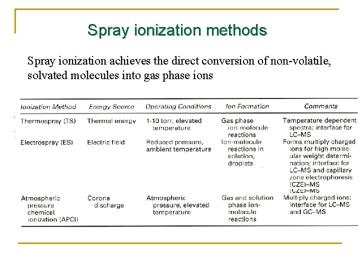
Spray ionization methods Spray ionization achieves the direct conversion of non-volatile, solvated molecules into gas phase ions
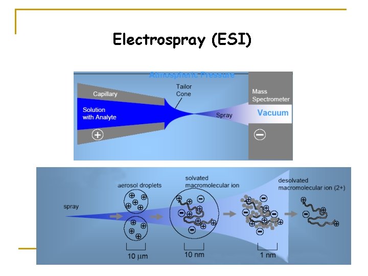
Electrospray (ESI)
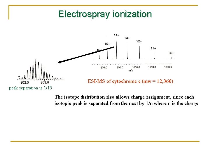
Electrospray ionization ESI-MS of cytochrome c (mw = 12, 360) peak separation is 1/15 The isotope distribution also allows charge assignment, since each isotopic peak is separated from the next by 1/n where n is the charge
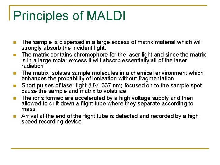
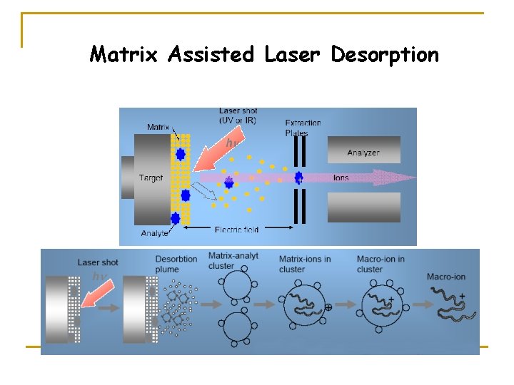
Principles of MALDI n n n The sample is dispersed in a large excess of matrix material which will strongly absorb the incident light. The matrix contains chromophore for the laser light and since the matrix is in a large molar excess it will absorb essentially all of the laser radiation The matrix isolates sample molecules in a chemical environment which enhances the probability of ionization without fragmentation Short pulses of laser light (UV, 337 nm) focused on to the sample spot cause the sample and matrix to volatilize The ions formed are accelerated by a high voltage supply and then allowed to drift down a flight tube where they separate according to mass Arrival at the end of the flight tube is detected and recorded by a high speed recording device
Matrix Assisted Laser Desorption
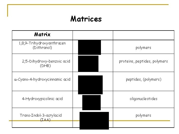
Matrices Matrix 1, 8, 9 -Trihydroxyanthracen (Dithranol) 2, 5 -Dihydroxy benzoic acid (DHB) polymers proteins, peptides, polymers -Cyano-4 -hydroxycinnamic acid peptides, (polymers) 4 -Hydroxypicolinic acid oligonucleotides Trans-Indol-3 -acrylacid (IAA) polymers
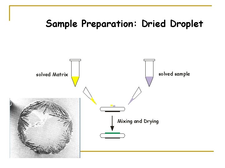
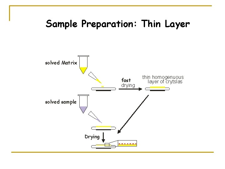
Sample Preparation: Dried Droplet solved Matrix solved sample Mixing and Drying
Sample Preparation: Thin Layer solved Matrix fast drying solved sample Drying thin homogenuous layer of crytslas
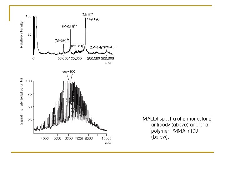
MALDI spectra of a monoclonal antibody (above) and of a polymer PMMA 7100 (below).
Secondary Ion Mass Spectrometry (SIMS)
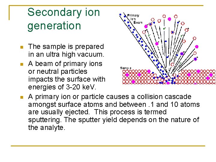
Secondary ion generation n The sample is prepared in an ultra high vacuum. A beam of primary ions or neutral particles impacts the surface with energies of 3 -20 ke. V. A primary ion or particle causes a collision cascade amongst surface atoms and between. 1 and 10 atoms are usually ejected. This process is termed sputtering. The sputter yield depends on the nature of the analyte.
Static SIMS n n Low ion flux is used. This means a small amount of primary ions is used to bombard the sample per area per unit time. Sputters away approximately only a tenth of an atomic monolayer. Ar+, Xe+, Ar, and Xe are the commonly used particles present in the primary particle beam, which has a diameter of 2 -3 mm. The analysis typically requires more than 15 minutes. This technique generates mass spectra data well suited for the detection of organic molecules.
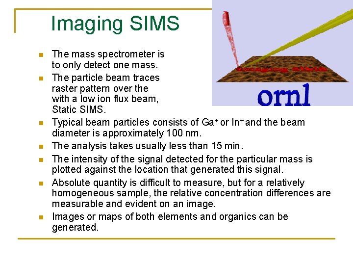
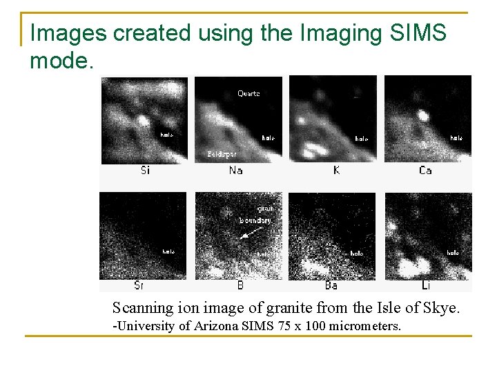
Imaging SIMS n n n n The mass spectrometer is set to only detect one mass. The particle beam traces a raster pattern over the sample with a low ion flux beam, much like Static SIMS. Typical beam particles consists of Ga+ or In+ and the beam diameter is approximately 100 nm. The analysis takes usually less than 15 min. The intensity of the signal detected for the particular mass is plotted against the location that generated this signal. Absolute quantity is difficult to measure, but for a relatively homogeneous sample, the relative concentration differences are measurable and evident on an image. Images or maps of both elements and organics can be generated.
Images created using the Imaging SIMS mode. Scanning ion image of granite from the Isle of Skye. -University of Arizona SIMS 75 x 100 micrometers.
Mass Analyzers
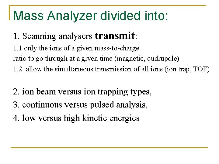
Mass Analyzer divided into: 1. Scanning analysers transmit: 1. 1 only the ions of a given mass-to-charge ratio to go through at a given time (magnetic, qudrupole) 1. 2. allow the simultaneous transmission of all ions (ion trap, TOF) 2. ion beam versus ion trapping types, 3. continuous versus pulsed analysis, 4. low versus high kinetic energies
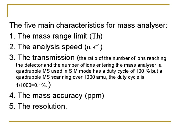
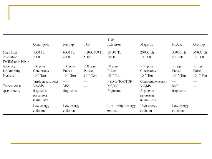
The five main characteristics for mass analyser: 1. The mass range limit (Th) 2. The analysis speed (u s− 1) 3. The transmission (the ratio of the number of ions reaching the detector and the number of ions entering the mass analyser, a quadrupole MS used in SIM mode has a duty cycle of 100 % but a quadrupole MS scanning over 1000 amu, the duty cycle is 1/1000=0. 1%. ) 4. The mass accuracy (ppm) 5. The resolution.
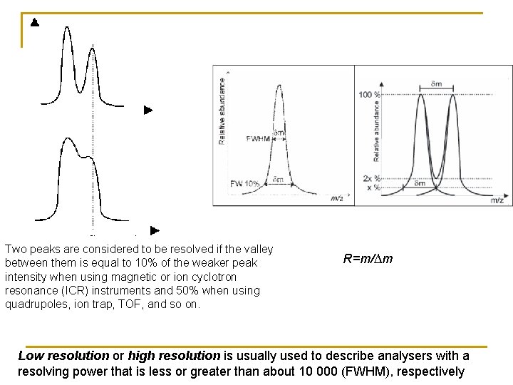
Two peaks are considered to be resolved if the valley between them is equal to 10% of the weaker peak intensity when using magnetic or ion cyclotron resonance (ICR) instruments and 50% when using quadrupoles, ion trap, TOF, and so on. R=m/∆m Low resolution or high resolution is usually used to describe analysers with a resolving power that is less or greater than about 10 000 (FWHM), respectively
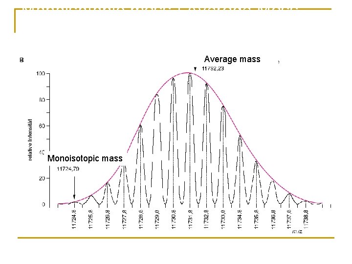
The first example is human insulin, a protein having the molecular formula C 257 H 383 N 65 O 77 S 6. The nominal mass of insulin is 5801 u using the integer mass of the most abundant isotope of each element, such as 12 u for carbon, 1 u for hydrogen, 14 u for nitrogen, 16 u for oxygen and 32 u for sulfur. Its monoisotopic mass of 5803. 6375 u is calculated using the exact masses of the predominant isotope of each element such as C=12. 0000 u, H=1. 0079 u, N=14. 0031 u, O=15. 9949 u and S=31. 9721 u.
Monoisotopic mass / Average Mass Average mass Monoisotopic mass
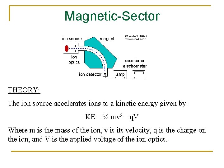
Magnetic-Sector THEORY: The ion source accelerates ions to a kinetic energy given by: KE = ½ mv 2 = q. V Where m is the mass of the ion, v is its velocity, q is the charge on the ion, and V is the applied voltage of the ion optics.
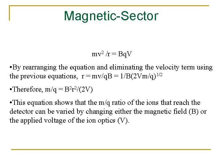
Magnetic-Sector • The ions enter the flight tube and are deflected by the magnetic field, B. • Only ions of mass-to-charge ratio that have equal centripetal and centrifugal forces pass through the flight tube: mv 2 /r = Bq. V, where r is the radius of curvature
Magnetic-Sector mv 2 /r = Bq. V • By rearranging the equation and eliminating the velocity term using the previous equations, r = mv/q. B = 1/B(2 Vm/q)1/2 • Therefore, m/q = B 2 r 2/(2 V) • This equation shows that the m/q ratio of the ions that reach the detector can be varied by changing either the magnetic field (B) or the applied voltage of the ion optics (V).
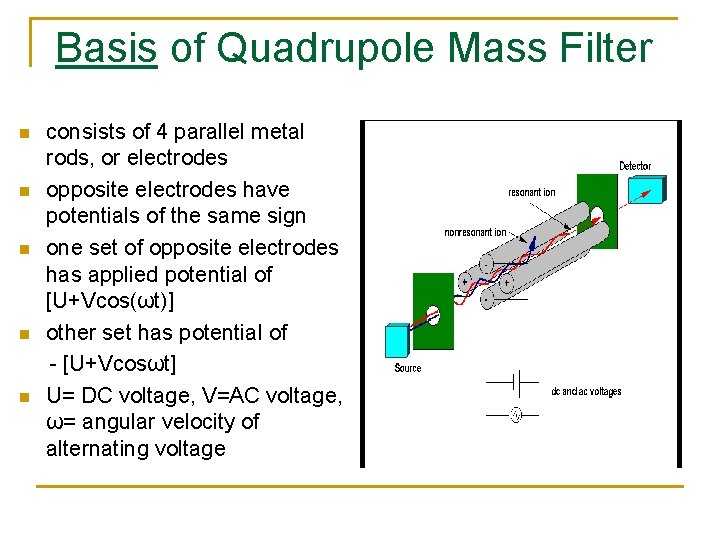
Basis of Quadrupole Mass Filter n n n consists of 4 parallel metal rods, or electrodes opposite electrodes have potentials of the same sign one set of opposite electrodes has applied potential of [U+Vcos(ωt)] other set has potential of - [U+Vcosωt] U= DC voltage, V=AC voltage, ω= angular velocity of alternating voltage
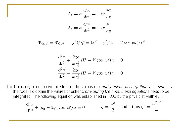
The trajectory of an ion will be stable if the values of x and y never reach r 0, thus if it never hits the rods. To obtain the values of either x or y during the time, these equations need to be integrated. The following equation was established in 1866 by the physicist Mathieu :
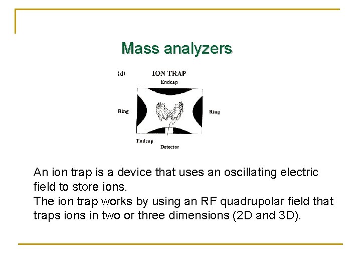
Mass analyzers An ion trap is a device that uses an oscillating electric field to store ions. The ion trap works by using an RF quadrupolar field that traps ions in two or three dimensions (2 D and 3 D).
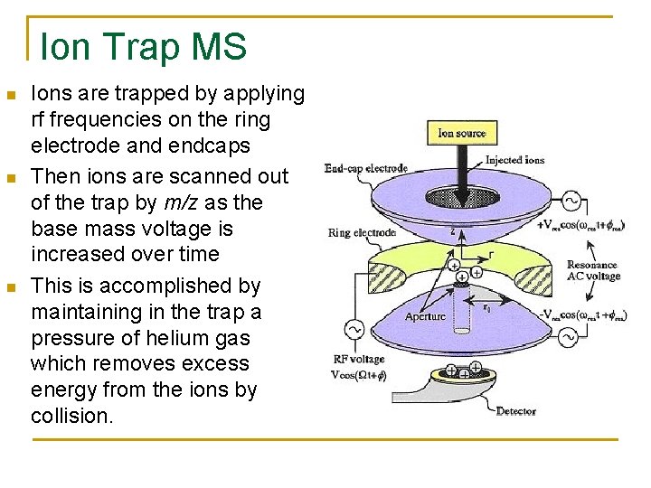
Ion Trap MS n n n Ions are trapped by applying rf frequencies on the ring electrode and endcaps Then ions are scanned out of the trap by m/z as the base mass voltage is increased over time This is accomplished by maintaining in the trap a pressure of helium gas which removes excess energy from the ions by collision.
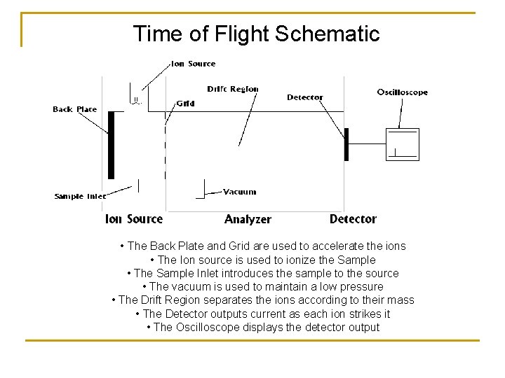
Time of Flight Schematic • The Back Plate and Grid are used to accelerate the ions • The Ion source is used to ionize the Sample • The Sample Inlet introduces the sample to the source • The vacuum is used to maintain a low pressure • The Drift Region separates the ions according to their mass • The Detector outputs current as each ion strikes it • The Oscilloscope displays the detector output
Time-of-Flight Converted to Mass n An accelerating potential (V) will give an ion of charge z an energy of z. V. This can be equated to the kinetic energy of motion and the mass (m) and the velocity (v) of the ion n z. V = 1/2 mv 2 n Since velocity is length (L) divided by time (t) then n m/Z = [2 Vt 2]/L 2 n V and L cannot be measured with sufficient accuracy but the equation can be rewritten n m/Z = B(t-A)2 where A and B are calibration constants that can be determined by calibrating to a known m/Z
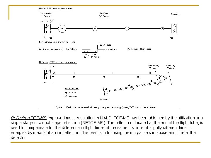
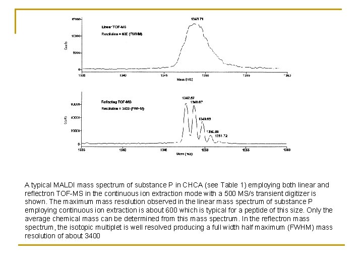
Reflectron TOF-MS Improved mass resolution in MALDI TOF-MS has been obtained by the utilization of a single-stage or a dual-stage reflectron (RETOF-MS). The reflectron, located at the end of the flight tube, is used to compensate for the difference in flight times of the same m/z ions of slightly different kinetic energies by means of an ion reflector. This results in focusing the ion packets in space and time at the detector
A typical MALDI mass spectrum of substance P in CHCA (see Table 1) employing both linear and reflectron TOF-MS in the continuous ion extraction mode with a 500 MS/s transient digitizer is shown. The maximum mass resolution observed in the linear mass spectrum of substance P employing continuous ion extraction is about 600 which is typical for a peptide of this size. Only the average chemical mass can be determined from this mass spectrum. In the reflectron mass spectrum, the isotopic multiplet is well resolved producing a full width half maximum (FWHM) mass resolution of about 3400
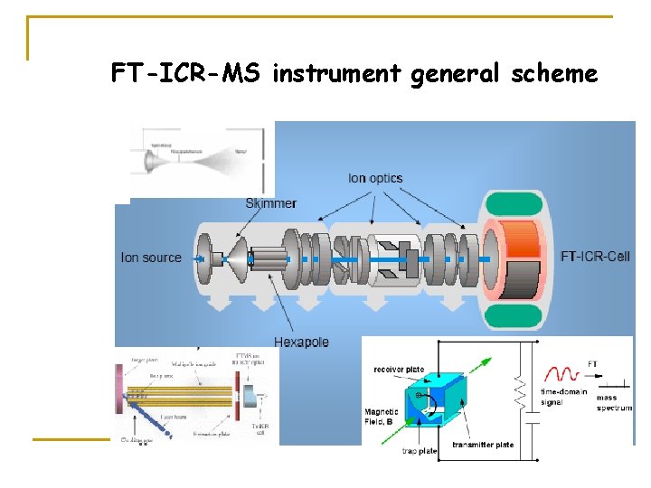
FT-ICR-MS instrument general scheme
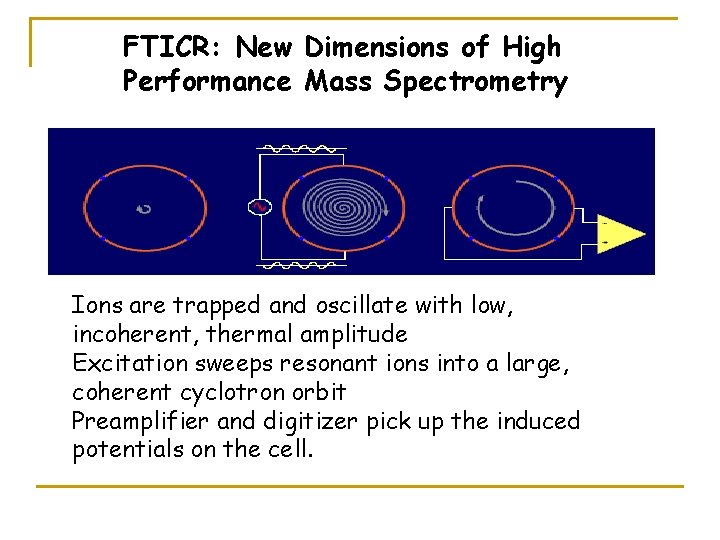
FTICR: New Dimensions of High Performance Mass Spectrometry Ions are trapped and oscillate with low, incoherent, thermal amplitude Excitation sweeps resonant ions into a large, coherent cyclotron orbit Preamplifier and digitizer pick up the induced potentials on the cell.
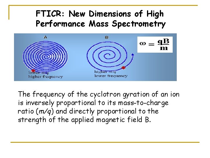
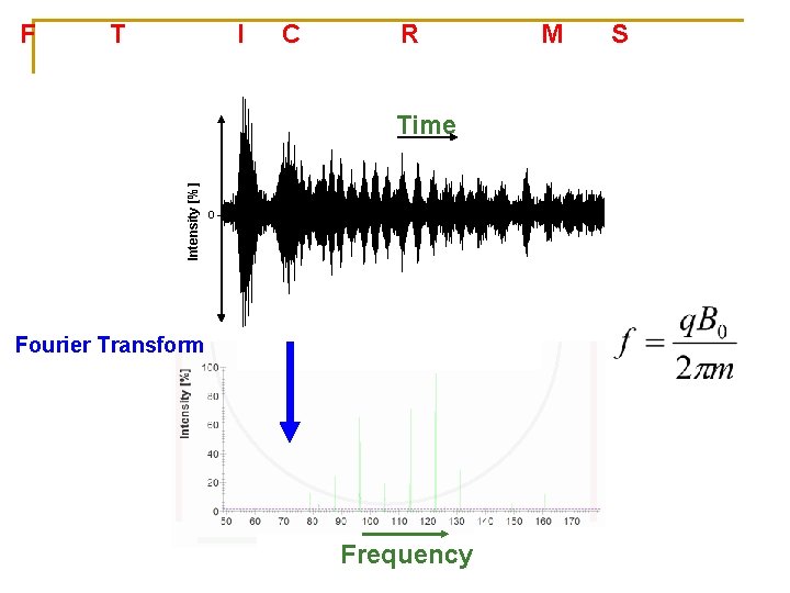
FTICR: New Dimensions of High Performance Mass Spectrometry The frequency of the cyclotron gyration of an ion is inversely proportional to its mass-to-charge ratio (m/q) and directly proportional to the strength of the applied magnetic field B.
Fourier Transform Ion Cyclotron Resonance Mass Spectrometry Intensity [%] Detection electrodes Excitation electrodes Fourier Transform Time + 0 + Fourier Transform Frequency
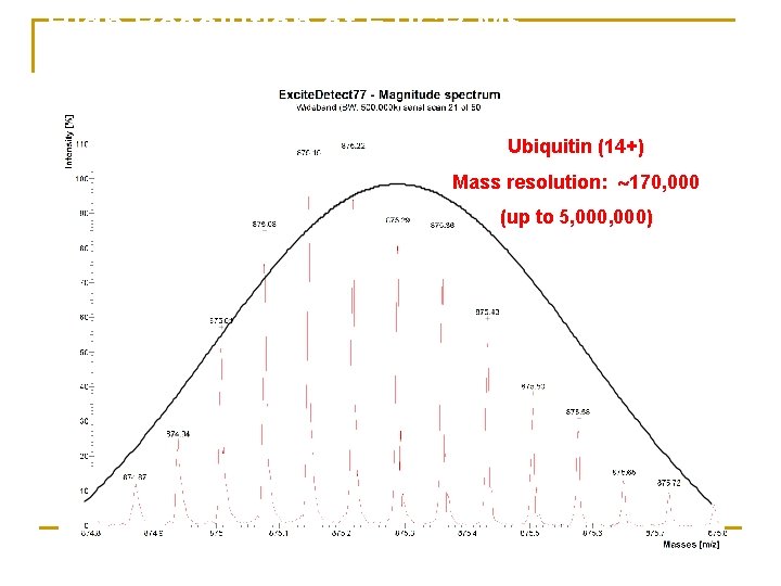
High Resolution of FTICR MS Ubiquitin (14+) Mass resolution: 170, 000 (up to 5, 000)
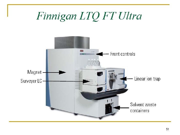
Finnigan LTQ FT Ultra 51
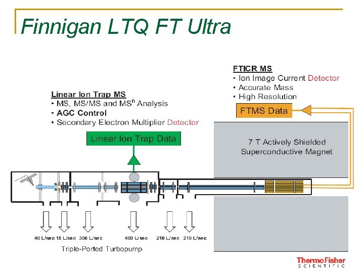
Finnigan LTQ FT Ultra 52
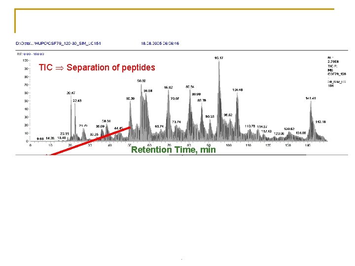
Biological samples Ceribrospinal fluid (CSF), 1µL Injection volume 200 n. L/min, Nanospray, TIC Separation of peptides MS Peptide mass Retention Time, min MS/MS Peptide sequence 660. 91 m/z
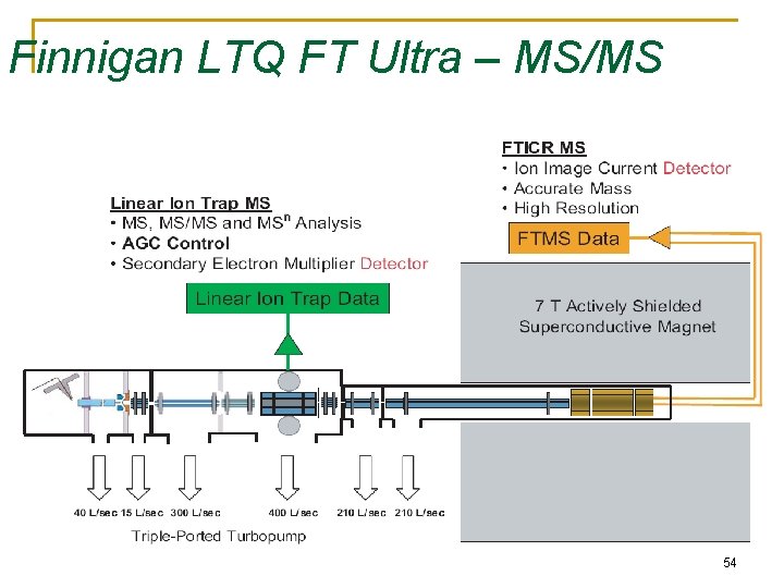
Finnigan LTQ FT Ultra – MS/MS 54
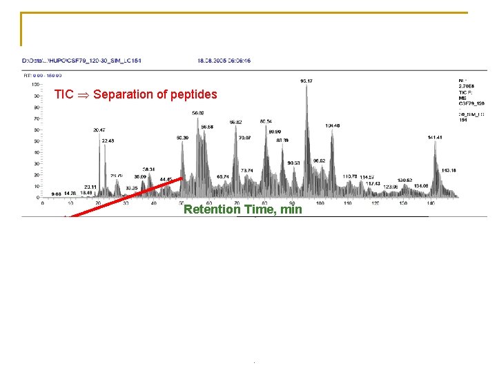
Biological samples Ceribrospinal fluid (CSF), 1µL Injection volume 200 n. L/min, Nanospray, TIC Separation of peptides MS Peptide mass Retention Time, min MS/MS Peptide sequence 660. 91 m/z
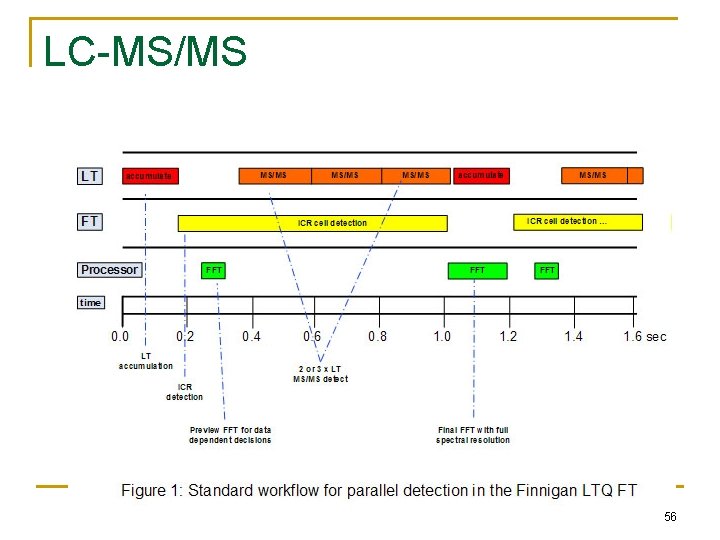
LC-MS/MS 56
Orbitrap - a new type of FTMS
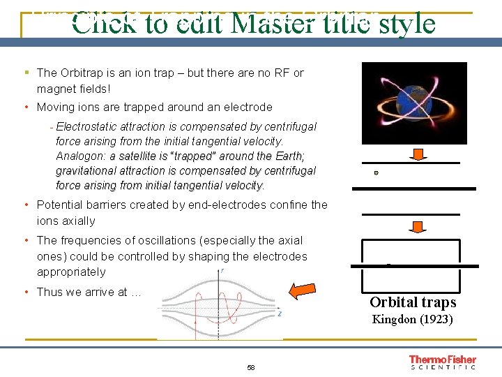
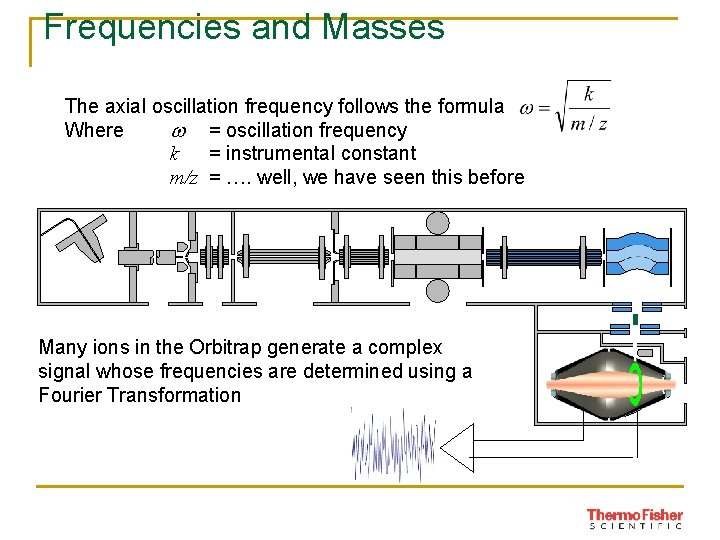
Principle of to Trapping in the Orbitrap Click edit Master title style § The Orbitrap is an ion trap – but there are no RF or magnet fields! • Moving ions are trapped around an electrode - Electrostatic attraction is compensated by centrifugal force arising from the initial tangential velocity. Analogon: a satellite is “trapped” around the Earth; gravitational attraction is compensated by centrifugal force arising from initial tangential velocity. • Potential barriers created by end-electrodes confine the ions axially • The frequencies of oscillations (especially the axial ones) could be controlled by shaping the electrodes appropriately • Thus we arrive at … Orbital traps Kingdon (1923) 58
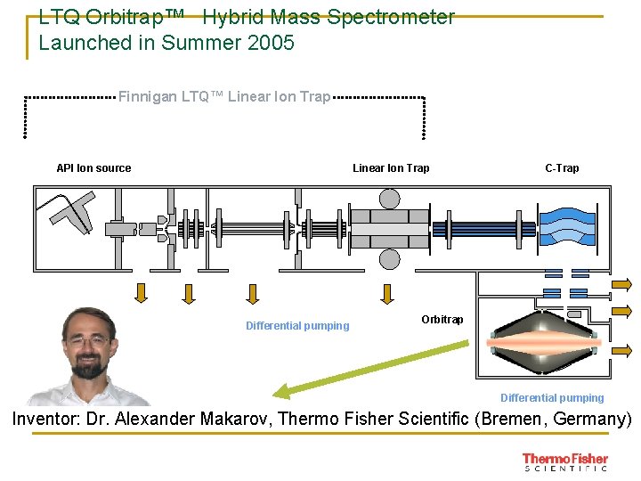
LTQ Orbitrap™ Hybrid Mass Spectrometer Launched in Summer 2005 Finnigan LTQ™ Linear Ion Trap API Ion source Linear Ion Trap Differential pumping C-Trap Orbitrap Differential pumping Inventor: Dr. Alexander Makarov, Thermo Fisher Scientific (Bremen, Germany)
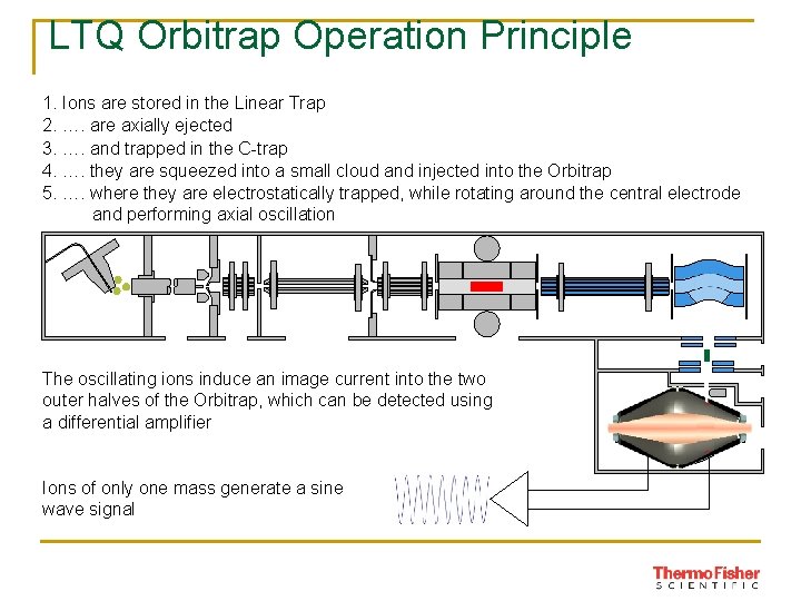
LTQ Orbitrap Operation Principle 1. Ions are stored in the Linear Trap 2. …. are axially ejected 3. …. and trapped in the C-trap 4. …. they are squeezed into a small cloud and injected into the Orbitrap 5. …. where they are electrostatically trapped, while rotating around the central electrode and performing axial oscillation The oscillating ions induce an image current into the two outer halves of the Orbitrap, which can be detected using a differential amplifier Ions of only one mass generate a sine wave signal
Frequencies and Masses The axial oscillation frequency follows the formula Where w = oscillation frequency k = instrumental constant m/z = …. well, we have seen this before Many ions in the Orbitrap generate a complex signal whose frequencies are determined using a Fourier Transformation
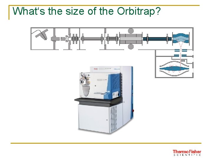
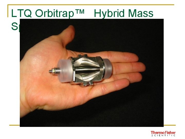
What‘s the size of the Orbitrap?
LTQ Orbitrap™ Hybrid Mass Spectrometer
Tandem mass spectrometers Uses of tandem mass spectrometry: (1) Characterize individual compounds in complex mixtures (2) Completely identify the molecular structure of a compound To accomplish either of these goals mass analysis must be carried out twice in a tandem instrument This can be achieved either by separating the mass analysis operations in space or in time
Tandem mass spectrometers
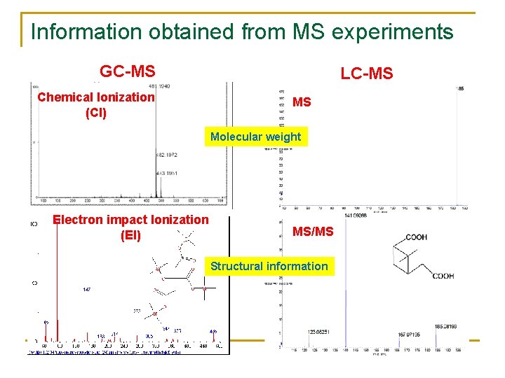
Information obtained from MS experiments GC-MS Chemical Ionization (CI) LC-MS MS Molecular weight Electron impact Ionization (EI) MS/MS Structural information
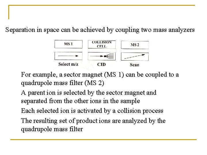
Separation in space can be achieved by coupling two mass analyzers For example, a sector magnet (MS 1) can be coupled to a quadrupole mass filter (MS 2) A parent ion is selected by the sector magnet and separated from the other ions in the sample Each selected ion is activated by a collision process The resulting set of product ions are analyzed by the quadrupole mass filter
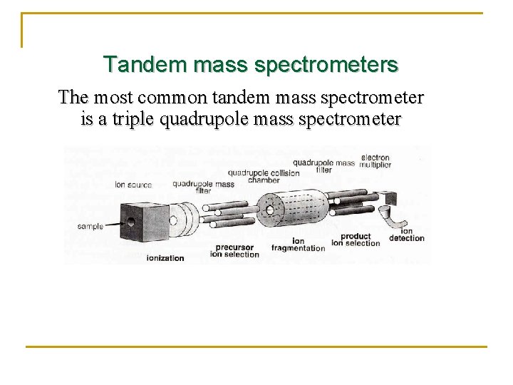
Tandem mass spectrometers The most common tandem mass spectrometer is a triple quadrupole mass spectrometer
Mass Spec Ion Detectors n n Faraday Cup Electron Multiplier and Channel Electron Multiplier Microchannel Plate Daly Detector (Scintillation Counter or Photomultiplier)
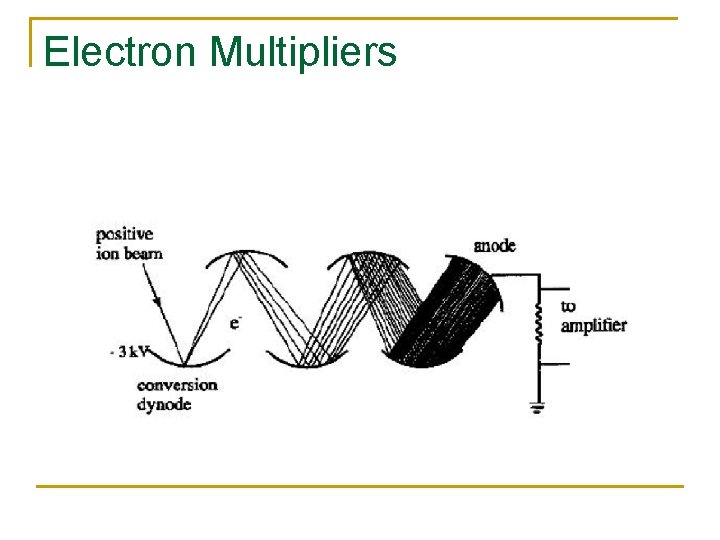
Electron Multipliers
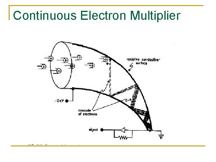
Continuous Electron Multiplier
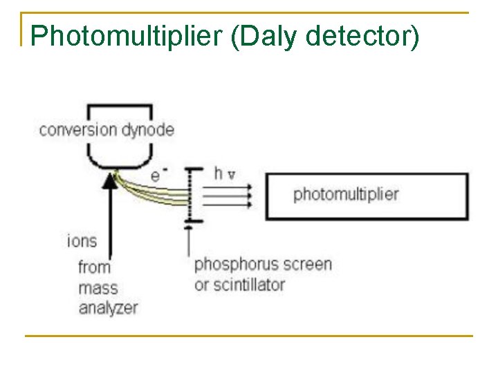
Photomultiplier (Daly detector)
Photomultiplier n n n Also called daly detector or scintillation counter Metal dynode emits secondary electrons Secondary electrons hit phosphorus screen and trigger photon emission; photon abundance measured by photomultiplier Advantage: keep detector in vacuum -- no contamination = low noise and long lifetime Disadvantage: cannot be exposed to light
Data Collection n Typically, the computer controls: q q Scanning of mass spec Data acquisition Data processing Interpretation of data (generation of spectra; possible comparison to spectra in database)
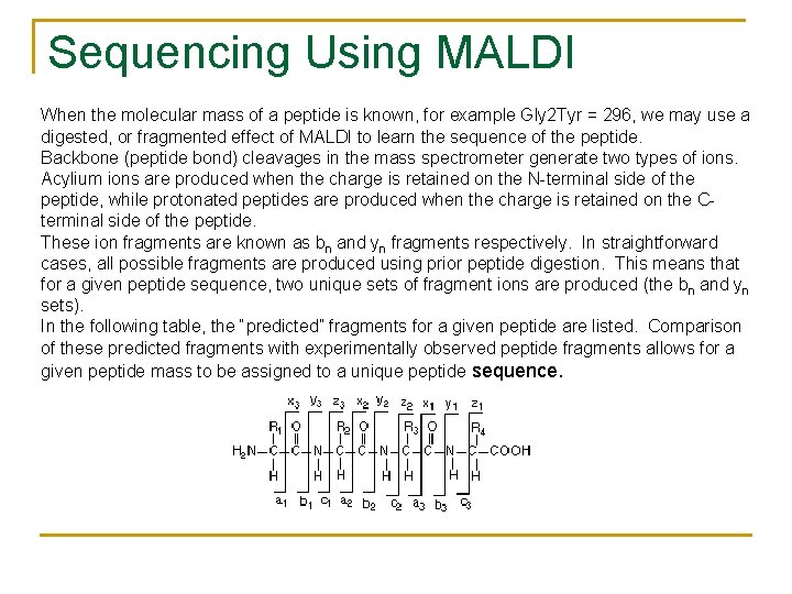
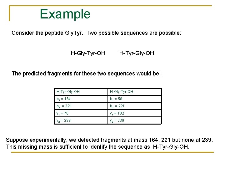
Sequencing Using MALDI When the molecular mass of a peptide is known, for example Gly 2 Tyr = 296, we may use a digested, or fragmented effect of MALDI to learn the sequence of the peptide. Backbone (peptide bond) cleavages in the mass spectrometer generate two types of ions. Acylium ions are produced when the charge is retained on the N-terminal side of the peptide, while protonated peptides are produced when the charge is retained on the Cterminal side of the peptide. These ion fragments are known as bn and yn fragments respectively. In straightforward cases, all possible fragments are produced using prior peptide digestion. This means that for a given peptide sequence, two unique sets of fragment ions are produced (the bn and yn sets). In the following table, the “predicted” fragments for a given peptide are listed. Comparison of these predicted fragments with experimentally observed peptide fragments allows for a given peptide mass to be assigned to a unique peptide sequence.
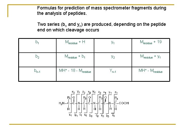
Formulas for prediction of mass spectrometer fragments during the analysis of peptides. Two series (bn and yn) are produced, depending on the peptide end on which cleavage occurs b 1 Mresidue + H y 1 Mresidue + 19 b 2 Mresidue + b 1 y 2 Mresidue + y 1 bn-1 MH+ - 18 - Mresidue Yn-1 MH+ - Mresidue
Example Consider the peptide Gly. Tyr. Two possible sequences are possible: H-Gly-Tyr-OH H-Tyr-Gly-OH The predicted fragments for these two sequences would be: H-Tyr-Gly-OH H-Gly-Tyr-OH b 1 = 164 b 1 = 58 b 2 = 221 y 1 = 76 y 1 = 182 y 2 = 239 Suppose experimentally, we detected fragments at mass 164, 221 but none at 239. This missing mass is sufficient to identify the sequence as H-Tyr-Gly-OH.
Peptide Fingerprinting n MALDI may be used to determine an exact “peptide fingerprint” of a section of a protein that carries a “disease” or differs from the normal protein in some way.
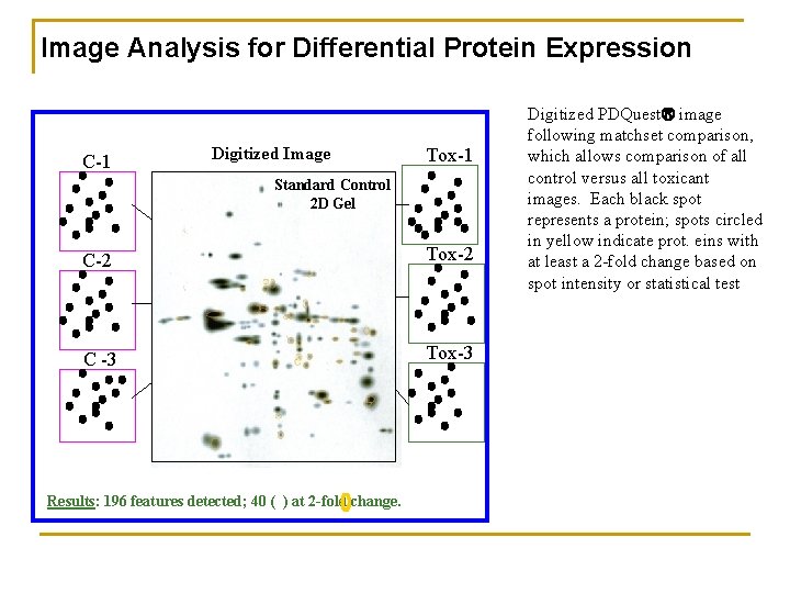
Image Analysis for Differential Protein Expression C-1 Digitized Image Tox-1 Standard Control 2 D Gel C-2 Tox-2 C -3 Tox-3 Results: 196 features detected; 40 ( ) at 2 -fold change. Digitized PDQuest image following matchset comparison, which allows comparison of all control versus all toxicant images. Each black spot represents a protein; spots circled in yellow indicate prot. eins with at least a 2 -fold change based on spot intensity or statistical test
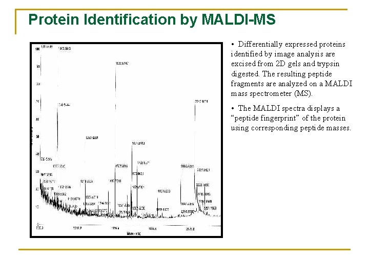
Protein Identification by MALDI-MS • Differentially expressed proteins identified by image analysis are excised from 2 D gels and trypsin digested. The resulting peptide fragments are analyzed on a MALDI mass spectrometer (MS). • The MALDI spectra displays a “peptide fingerprint” of the protein using corresponding peptide masses.
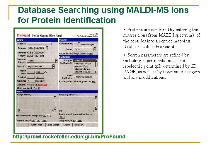
Database Searching using MALDI-MS Ions for Protein Identification • Proteins are identified by entering the masses (ions from MALDI spectrum) of the peptides into a peptide mapping database such as Pro. Found. • Search parameters are refined by including experimental mass and isoelectric point (p. I) determined by 2 D PAGE, as well as by taxonomic category and any modifications. http: //prowl. rockefeller. edu/cgi-bin/Pro. Found