Mass Savings and Finite Element Analysis FEA Preparation


![Structural and Thermal Budgets MASS (kg) Components [8] E-MOD floor beams & overlay 7. Structural and Thermal Budgets MASS (kg) Components [8] E-MOD floor beams & overlay 7.](https://slidetodoc.com/presentation_image_h2/2cd04a52722ddd0edca97d5be5bdc18e/image-8.jpg)


![FEA – Set Up [17] AAE 450 Spring 2009 [Tim Rebold] [STRC] FEA – Set Up [17] AAE 450 Spring 2009 [Tim Rebold] [STRC]](https://slidetodoc.com/presentation_image_h2/2cd04a52722ddd0edca97d5be5bdc18e/image-17.jpg)
- Slides: 17

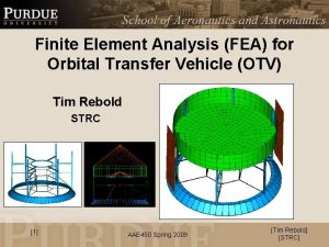
Mass Savings and Finite Element Analysis (FEA) Preparation for Orbital Transfer Vehicle (OTV) 100 gram Case Tim Rebold STRC [1] AAE 450 Spring 2009 [Tim Rebold] [STRC]

Mass Savings A-A Lander § Savings 1. 2. 3. 4. § Skin panel reduction Reduced OTV diameter to match Lunar Lander Attachment interface being separated Modified truss and electronic floor beam dimensions A A Added supports stiffen stringers for mounting equipment Skirt / Payload Attach Fitting (PAF) Ø = 2. 06 m Standard launch vehicle (Dnepr) interface Mass Reduced § § § [2] Mass reduction: 27. 73 kg (59% reduction) Total Structural Mass: 49. 37 kg (excluding 14. 3 kg thermal control) finert = 0. 22 AAE 450 Spring 2009 *Not to scale [Tim Rebold] [STRC]

FEA Preparation § Model – Thin wall & beam elements model structural components – Lumped masses represent non-structural components § Concerns – Assumption used to size truss frame was based on capability to only carry axial loads • Moments might produce yielding stresses – Stresses at joints and connections – Axial and lateral modes (resonant frequencies) • Can stiffen skirt until requirements are satisfied – Vibrations transmitted to electronics and solar array structure [3] AAE 450 Spring 2009 [Tim Rebold] [STRC]

References (1) Delta II Payload Planners Guide http: //snebulos. mit. edu/projects/reference/launch_vehicles/Delta/DELTA_II_User_ Guide_Update_0103. pdf (2) Skullney, W. E. Fundamentals of Space Systems. 2 nd Edition. Ch. 8, pp. 465 -564 Oxford University Press, 2005. (3) “Properties of Materials. ” 2009. Purdue University. http: //www. lib. purdue. edu/eresources/wts/result. html? WTSApp. Name=Lib_edupac kk (4) Sun, C. T. Mechanics of Aircraft Structures. New York: John Wiley and Sons, 2006. (5) Dnepr User’s Guide http: //snebulos. mit. edu/projects/reference/launch_vehicles/DNEPR/Dnepr_User_G uide. pdf (6) Larson, W. J. Spacecraft Structures and Mechanisms. Microcosm, Inc. , 1995 [4] AAE 450 Spring 2009 [Tim Rebold] [STRC]

Future Work § FEM analysis – Obtain better approximation of center of mass and inertia values – Perform modal analysis to see if OTV meets stiffness requirements placed on launch vehicle payloads – Perform stress and strain analysis for various load cases – Ensure all components will be protected from a dynamic environment [5] AAE 450 Spring 2009 [Tim Rebold] [STRC]

Arbitrary Payload Case § Variables – OTV payload (Lander) : Expected to scale linearly – Number of engines & propulsion system size : Increases structural support but should be scaled relatively linearly – Solar Array size : Increased structural support mass and will most likely be scaled exponentially [6] AAE 450 Spring 2009 [Tim Rebold] [STRC]

Mass Savings Summary Aluminum 6061 -T 6 material selected for all structural elements MASS SAVINGS (kg) Components Old New Reduction Savings (%) E-MOD floor beams 7. 07 3. 80 3. 27 46 E-MOD floor overlay 4. 88 3. 52 1. 36 28 Shear / Skin panels 13. 82 3. 91 9. 91 72 Propulsion support frame 4. 30 2. 07 2. 23 52 Stringers / Stiffeners 6. 28 6. 07 0. 21 3 PAF release 10. 75 0 10. 75 100 Total 47. 10 19. 37 27. 73 59 Abbreviations • E-MOD: Electronics Module [7] AAE 450 Spring 2009 [Tim Rebold] [STRC]
![Structural and Thermal Budgets MASS kg Components 8 EMOD floor beams overlay 7 Structural and Thermal Budgets MASS (kg) Components [8] E-MOD floor beams & overlay 7.](https://slidetodoc.com/presentation_image_h2/2cd04a52722ddd0edca97d5be5bdc18e/image-8.jpg)
Structural and Thermal Budgets MASS (kg) Components [8] E-MOD floor beams & overlay 7. 32 Shear / Skin panels 3. 91 Propulsion support frame 2. 07 Stringers / Stiffeners 6. 07 Integration (Lander and propulsion module) 22* Fasteners (welds, rivets, bolts, adhesives) 8* E-MOD thermal control 11. 1 Propulsion thermal control 3. 2 Total (structures) 49. 37 Total (thermal) 14. 3 TOTAL 63. 67 AAE 450 Spring 2009 *Estimates [Tim Rebold] [STRC]

Dimensions - OTV x Lander 1. 8 m 1. 45 m Stiffener / C-Channels 0. 95 m Skin panels removed 0 m Skirt / Payload Attach Fitting (PAF) *Not to scale [9] Ø = 2. 06 m AAE 450 Spring 2009 [Tim Rebold] [STRC]

Integration Ring Dimensions 1 cm 3. 6 cm Lander 2. 00 m *Not to scale [10] Ø = 2 cm (6 equally spaced over C-Channels) AAE 450 Spring 2009 Mass = 5. 93 kg [Tim Rebold] [STRC]

Payload Attach Fitting Dimensions A Mass = 40. 08 kg A 6 cm Cross Section 3. 6 cm 2. 12 m 1 cm Web thickness = 4 mm 14. 8 cm Ø = 4 cm (8 equally spaced) 1 cm A-A 6 cm *Not to scale [11] AAE 450 Spring 2009 [Tim Rebold] [STRC]

Dimensions – C-Channels 2. 75 cm Cross sectional area = 0. 000252 m 2 Length = 1. 45 m Mass = 1. 0114 kg ρ = 2768 kg/m 3 3 mm 3. 5 cm Stringer / Stiffener Cross-Section Why a C-Channel? • Easy access for making connections to other members • Provides a relatively high moment of inertia *Not to scale [12] AAE 450 Spring 2009 [Tim Rebold] [STRC]

Dimensions – Propulsion Support Electronics Module 0. 50 m 0. 66 m 0. 57 m 0. 30 m (includes 1 cm clearance over Xenon tank) Ø = 0. 58 m 0. 65 m 0. 36 m 0. 90 m OTV Base 0. 20 m *Not to scale [13] AAE 450 Spring 2009 [Tim Rebold] [STRC]

Dimensions – Propulsion Support Frame 4 Stringer / Stiffener Cross-Section Might need to thicken flange to tolerate local stresses Weld 2 b 3 Pinned joint Propulsion truss frame 1 [14] Member 1 2 3 4 t (mm) 0. 77 3. 2 0. 5 1. 52 h (cm) 0. 75 2. 20 0. 75 AAE 450 Spring 2009 b (cm) 0. 75 2. 20 0. 75 t h b [Tim Rebold] [STRC]

Dimensions – Electronic Module Electronics Module Ø = 0. 25 m 0. 50 m Thin (0. 5 mm) floor skin 0. 03 m 0. 05 m, Floor beam height Components not placed under lander nozzle and above floor lacking beam supports 6 beams spanning from OTV stiffeners of length 0. 57 m Beams welded to thin (mm’s) circular ring *Not to scale [15] AAE 450 Spring 2009 [Tim Rebold] [STRC]

Dimensions - Electronic Module Floor Support Electronic Module Support No. Beams t (mm) b (cm) h (cm) 6 2. 9 2. 5 5. 0 Battery DC / DC Converter Stringer / Stiffener Cross-Section PCDU PSU b Thin 0. 5 mm floor overlays beam supports h t Electronic Module floor beam supports b [16] AAE 450 Spring 2009 Weld Electronic Module floor beam supports Acronyms • PCDU: Power Conditioning Distribution Unit • PSU: Power Supply Unit [Tim Rebold] [STRC]
![FEA Set Up 17 AAE 450 Spring 2009 Tim Rebold STRC FEA – Set Up [17] AAE 450 Spring 2009 [Tim Rebold] [STRC]](https://slidetodoc.com/presentation_image_h2/2cd04a52722ddd0edca97d5be5bdc18e/image-17.jpg)
FEA – Set Up [17] AAE 450 Spring 2009 [Tim Rebold] [STRC]
 Phases of finite element method
 Non finite subordinate clause
 What is finite verb
 Learning objectives for finite and non finite verbs
 Finite and non finite clause
 Finite and non finite
 Truss finite element analysis
 Finite element analysis
 Difference between fea and fem
 Finite element method example
 Hourglass modes finite element method
 Cst
Cst Image preprocessing
 Finite element
 Fem geotechnics
 Finite element method
 Finite element method
 Finite element method

