Manufacturing Systems Dr Apiwat Muttamara Agenda Background of

Manufacturing Systems Dr. Apiwat Muttamara

Agenda • • • Background of Manufacturing Group Cell Overview Manufacturing System FMS

• Craft Manufacturing • Mass Manufacturing • Lean Manufacturing

Craft Manufacturing • Late 1800’s • Car built on blocks in the barn as workers walked around the car. • Built by craftsmen with pride • Components hand-crafted, hand-fitted • Excellent quality • Very expensive • Few produced

Mass Manufacturing • Assembly line - Henry Ford 1920 s • Low skilled labor, simplistic jobs, no pride in work • Interchangeable parts • Lower quality • Affordably priced for the average family • Billions produced - identical

Henry Ford - Standards “To standardize a method is to choose out of the many methods the best one, and use it. Standardization means nothing unless it means standardizing upward. Today’s standardization, instead of being a barricade against improvement, is the necessary foundation on which tomorrow’s improvement will be based. If you think of “standardization” as the best that you know today, but which is to be improved tomorrow - you get somewhere. But if you think of standards as confining, then progress stops. ” Henry Ford, 1926 Today & Tomorrow

Lean Manufacturing • Cells or flexible assembly lines • Broaden jobs, highly skilled workers, proud of product • Interchangeable parts, even more variety • Excellent quality mandatory • Costs being decreased through process improvements. • Global markets and competition.

New Paradigm: Non-Blaming Culture Management creates a culture where: • Problems are recognized as opportunities • It’s okay to make legitimate mistakes • Problems are exposed because of increased trust • People are not problems they are problem solvers PROBLEMS SOLUTIONS • Emphasis is placed on finding solutions instead of “who did it”

Who wants what. . . $ Cash !! Value !! Customer Low Cost High Quality Availability Your Company Profit Repeat Business Growth

Interactions of many processes, products and design decisions made in the engineering of a product. – Machine requirements planning – Process planning – Production planning – Concurrent engineering

Personnel, vendor, customer Factories, Facilities, Machines, tools

Physical systems • The classification of manufacturing system, which uses the material flow type as its basic; – Product-base – Process-base – Cellular Process Layout Product Layout Cellular Layout

FUNCTIONAL LAYOUTS ARE INEFFICIENT Drilling Milling Lathe L L M M D D Grinding L L L M M Assembly L A A Receiving and Shipping A A G G G PROCESS-TYPE LAYOUT

Process Layout Characteristics • Advantages – Deep knowledge of the process – Common tooling and fixtures – Most Flexible -- can produce many different part types • Disadvantages – – Spaghetti flow -- everything gets all tangled up Lots of in-process materials Hard to control inter-department activities Can be difficult to automate

PRODUCT LAYOUT Part #1 L L M D G A Receiving L M G A G Part #2 Part #3 L M D Shipping

Product Layout Characteristics • Advantages – Easy to control -- input control – Minimum material handling -- frequently linked to the next process – Minimal in-process materials – Can be more easily automated • Disadvantages – Inflexible -- can only produce one or two parts – Large setup – Duplicate tooling is required for all cells

CELLULAR LAYOUT Cell #2 Cell #1 D D M I D I L Cell #3 L L D M M I M

Cellular Layouts 1. Identify families of parts with similar flow paths 2. Group machines into cells based on part families 3. Arrange cells so parts movement is minimized 4. Locate large shared machines at point of use © 2000 by Prentice-Hall Inc Russell/Taylor Oper Mgt 3/e Ch 7 - 33

Original Process Layout Assembly 4 6 7 5 8 2 1 A © 2000 by Prentice-Hall Inc Russell/Taylor Oper Mgt 3/e 10 3 B 9 C 12 11 Raw materials Ch 7 - 34

Part Routing Matrix PARTS A B C D E F G H 1 x 2 x 3 4 x x x x © 2000 by Prentice-Hall Inc Russell/Taylor Oper Mgt 3/e x MACHINES 5 6 7 8 9 x x x 10 11 12 x x x Ch 7 - 35

Part Routing Matrix Reordered To Highlight Cells PARTS A D F C G B H E 1 x x x © 2000 by Prentice-Hall Inc Russell/Taylor Oper Mgt 3/e 2 x x 4 x x x 8 x x x MACHINES 10 3 6 9 x x x 5 11 12 x x x x x 7 x x Ch 7 - 36

Cellular Layout Solution © 2000 by Prentice-Hall Inc Russell/Taylor Oper Mgt 3/e Ch 7 - 37

Advantages Of Cellular Layouts • • • Reduced material handling and transit time Reduced setup time Reduced work-in-process inventory Better use of human resources Easier to control Easier to automate © 2000 by Prentice-Hall Inc Russell/Taylor Oper Mgt 3/e Ch 7 - 38

Disadvantages Of Cellular Layouts • Inadequate part families • Poorly balanced cells • Expanded training and scheduling of workers • Increased capital investment © 2000 by Prentice-Hall Inc Russell/Taylor Oper Mgt 3/e Ch 7 - 39

Goal and Objective • GOAL -- Today’s manufacturing engineer needs to identify and locate the most efficient method to produce a product (inhouse or not) • OBJECTIVE -- reduce time to market, increase quality, reduce cost, and operate in a tight capital environment

Today’s Situation • Moving form paper driven systems or from “stand-alone” business and engineering systems • Selling under-utilized resources to increase profit • Terminate inefficient (non competitive) activities

Vocabulary • Glossary of terms – CIM, CAD, CAM, CAD/CAM, NC, CNC, FMS, Simultaneous engineering, Concurrent engineering, Agile Engineering, Product Engineering, Process Engineering Production Engineering, . . .
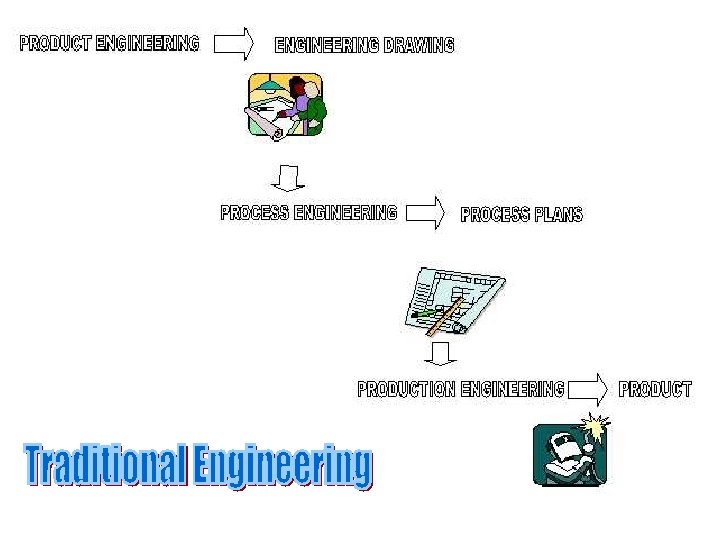

Engineering

Product Engineering

Process Engineering

Production Engineering
 INTEGRATION ENGINEERING – tools and techniques")
A Vision of Integrated Engineering Systems (cont. ) INTEGRATION ENGINEERING – tools and techniques that can be used to assist in combining planning, design, construction and management of a product.
 • INTEGRATED ENGINEERING – planning, designing, construction")
A Vision of Manufacturing Systems (cont. ) • INTEGRATED ENGINEERING – planning, designing, construction and management of a product.

Concurrent or simultaneous engineering • Performing all business activities in unison • Making wise real-time economic decisions • Team concepts

HIGH EX PR OD UC T TRANSFER LINE VOLUME FL IBI LIT Y IO SPECIAL SYSTEM CIM NC AP A CI TY FLEXIBLE MANUFACTURING SYSTEM MANUFACTURING Cells Stand-alone N/C MACHINERY LOW VARIETY HIGH

High-volume, Low-variety Production system • • • Transfer line Production rates are high Inflexibility Lines are expensive Low unit cost of production

Low-volume, High-variety Production system • • Stand-alone NC machine Highest level of Flexibility Low utilization and low production volume Unit cost -high **Tool changer, pallet changer ***Robot

Mid-volume, Mid-variety Production system • Discrete manufacturing • CIM can be classified as – Manufacturing cell – Special manufacturing system – Flexible manufacturing system

Manufacturing cell • Low to Mid volume • A variety of parts are manufactured in batch mode • A manufacturing cell is an FMS with out central control • More flexible than an FMS but lower production rate

Special Manufacturing system • A fixed-path material handling system links the machines together • Least flexible category of CIM system • Uses multi-spindle heads and low-level controller • High production rate and low unit production cost

Flexible Manufacturing System • Flexible machines, automated material handling system, automated tool changer, CMM, all under high level centralized computer control • Higher production rate than a manufacturing cell and much higher flexibility than a special manufacturing system
 • Using automated machines (DNC) & materials handling")
Production Technology Flexible Manufacturing Systems (FMS) • Using automated machines (DNC) & materials handling equipment together • Often connected to centralized computer • Also called automated work cell Auto Tool Chg. Machine 1 Robot or AGV Computer Auto Tool Chg. Machine 2

Flexible Manufacturing Systems • • • Automated machining operations Automated material handling Automated tool changers Computer controlled system Designed around size of parts processed & average processing time for parts • Can process wide variety of items quickly

Production Technology • Advantages – – FMS Faster, lower-cost changes from one part to another Lower direct labor costs Reduced inventory Consistent, and perhaps better quality • Disadvantages – Limited ability to adapt to product or product mix changes – Requires substantial preplanning and capital expenditures – Technological problems of exact component positioning and precise timing – Tooling and fixture requirements

FMS Layouts

Open Field FMS Layout
 • Manufacturing system that combines CAM with engineering")
Production Technology Computer Integrated Manufacturing (CIM) • Manufacturing system that combines CAM with engineering (CAD), & production & inventory control • Computer-aided design (CAD) creates code to run DNC machines Top Mgmt CAD PIC DNC Robots AGV CAM
, or")
A Vision of Integrated Engineering Systems ENGINEERING -- the planning, designing, construction (manufacture), or management of machinery, roads, bridges, etc. .
 INTEGRATE – 1. to make or")
A Vision of Integrated Engineering Systems (cont. ) INTEGRATE – 1. to make or become whole or complete. – 2. to bring parts together as a whole. – 3. to remove barriers imposing segregation.
 INTEGRATED ENGINEERING – planning, designing, construction")
A Vision of Integrated Engineering Systems (cont. ) INTEGRATED ENGINEERING – planning, designing, construction and management of a product.

CIM
 • Production Planning – Resource, machine, cost, scheduling, line")
Computer aided Process Planning (CAPP) • Production Planning – Resource, machine, cost, scheduling, line balancing • Process Planning – initial form to a final form • Operation Planning – The act of preparing detailed work instructions to produce a part

PRODUCT REALIZATION Product design Process planning Process, machine knowledge Operation programming Verification Scheduling Execution Scheduling knowledge

PROCESS PLANNING Design Machine Tool Process Planning Scheduling and Production Control

PROBLEMS FACING MANUFACTURING INDUSTRY Fact: Only 11% of the machine tools in the U. S. are programmable. More than 53% of the metal-working plants in the U. S. do not have even one computer-controlled machine. Thailand ? ?

Some problems: Cannot justify the cost Lack of expertise in using such machines Too small a batch size to offset the planning and programming costs

Planning Knowledge • Universal Level Knowledge • Shop Level Knowledge • Machine Level Knowledge

ENGINEERING DESIGN MODELING CSG MODEL B-REP MODEL Boundary representation Constructive solid geometry

INTERACTION OF PLANNING FUNCTIONS GEOMETRIC REASONING • global & local geometry PROCESS SELECTION • process capability • process cost CUTTER SELECTION • available tools • tool dimension and geometry • geometric constraints MACHINE TOOL SELECTION • machine availability, cost • machine capability SETUP PLANNING • feature relationship • approach directions • process constraints • fixture constraints FIXTURE PLANNING • fixture element function • locating, supporting, and clamping surfaces • stability CUTTER PATH GENERATION • feature merging and split • path optimization • obstacle and interference avoidance

PROCESS SELECTION Drill

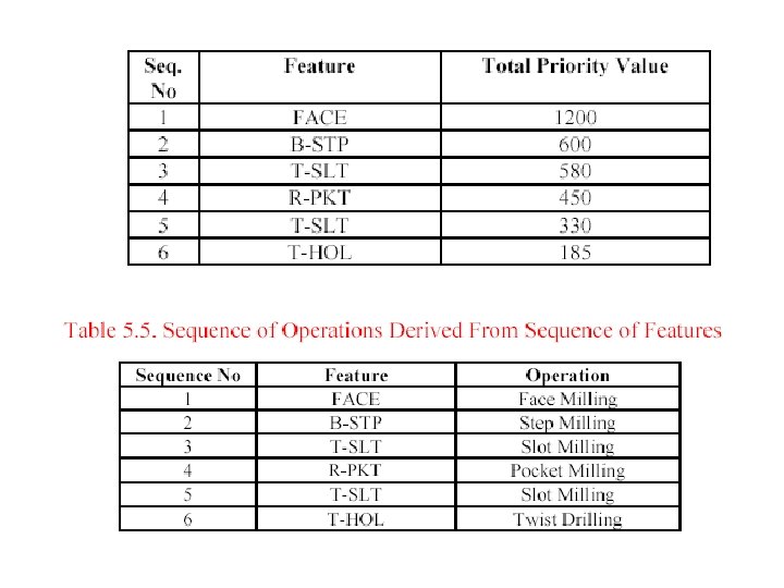
PROCESS PLAN • Also called : operation sheet, route sheet, operation planning summary, or another similar name. • The detailed plan contains: route processes process parameters machine and tool selections fixtures • How detail the plan is depends on the application. • Operation: a process • Operation Plan (Op-plan): contains the description of an operation, includes tools, machines to be used, process parameters, machining time, etc. • Op-plan sequence: Summary of a process plan.

EXAMPLE PROCESS PLANS Detailed plan Rough plan

FACTORS AFFECTING PROCESS PLAN SELECTION • Shape • Tolerance • Surface finish • Size • Material type • Quantity • Value of the product • Urgency • Manufacturing system itself • etc.
 COMPUTER-AIDED VARIANT GT based Computer aids for editing")
PROCESS PLANNING CLASSIFICATION MANUAL (Creation, Modification) COMPUTER-AIDED VARIANT GT based Computer aids for editing Parameters selection GENERATIVE Some kind of decision logic Decision tree/table Artificial Intelligence Objective-Oriented Still experience based AUTOMATIC Design understanding Geometric reasoning capability

REQUIREMENTS IN MANUAL PROCESS PLANNING • ability to interpret an engineering drawing. • familiar with manufacturing processes and practice. • familiar with tooling and fixtures. • know what resources are available in the shop. • know how to use reference books, such as machinability data handbook. • able to do computations on machining time and cost. • familiar with the raw materials. • know the relative costs of processes, tooling, and raw materials.

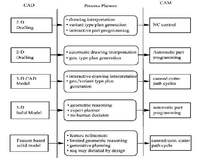
INDUSTRIAL SOLUTION PRODUCT CONCEPT CAD N 0010 G 70 G 90 T 08 M 06 N 0020 G 00 X 2. 125 Y-0. 475 Z 4. 000 S 3157 N 0030 G 01 Z 1. 500 F 63 M 03 N 0040 G 01 Y 4. 100 N 0050 G 01 X 2. 625 N 0060 G 01 Y 1. 375 N 0070 G 01 X 3. 000 N 0080 G 03 Y 2. 625 I 3. 000 J 2. 000 N 0090 G 01 Y 2. 000 N 0100 G 01 X 2. 625 N 0110 G 01 Y-0. 100 N 0120 G 00 Z 4. 000 T 02 M 05 N 0130 F 9. 16 S 509 M 06 N 0140 G 81 X 0. 750 Y 1. 000 Z-0. 1 R 2. 100 M 03 N 0150 G 81 X 0. 750 Y 3. 000 Z-0. 1 R 2. 100 N 0160 G 00 X-1. 000 Y-1. 000 M 30 CAM HUMAN - decision making COMPUTER - geometric computation, data handling CUTTER PATH

PROCESS PLANNING STEPS • Study the overall shape of the part. Use this information to classify the part and determine the type of workstation needed. • Thoroughly study the drawing. Try to identify every manufacturing features and notes. • If raw stock is not given, determine the best raw material shape to use. • Identify datum surfaces. Use information on datum surfaces to determine the setups. • Select machines for each setup. • For each setup determine the rough sequence of operations necessary to create all the features.
 • Sequence the operations determined in the previous step. •")
PROCESS PLANNING STEPS (continue) • Sequence the operations determined in the previous step. • Select tools for each operation. Try to use the same tool for several operations if it is possible. Keep in mind the trade off on tool change time and estimated machining time. • Select or design fixtures for each setup. • Evaluate the plan generate thus far and make necessary modifications. • Select cutting parameters for each operation. • Prepare the final process plan document.

COMPUTER-AIDED PROCESS PLANNING ADVANTAGES 1. It can reduce the skill required of a planner. 2. It can reduce the process planning time. 3. It can reduce both process planning and manufacturing cost. 4. It can create more consistent plans. 5. It can produce more accurate plans. 6. It can increase productivity.

WHY AUTOMATED PROCESS PLANNING • Shortening the lead-time • Manufacturability feedback • Lowering the production cost • Consistent process plans

PROCESS PLANNING Design Machining features Workpiece Selection Process Selection Tool Selection Feed, Speed Selection Operation Sequencing Setup Planning Fixturing Planning Part Programming

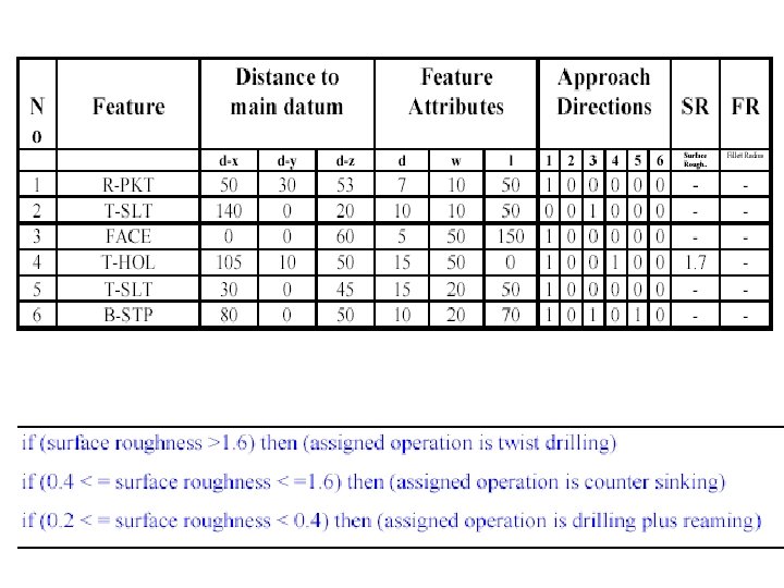
Process Constraints • Geometric Constraints – Drill on Slanted Surface, Flat Bottomed hole • Technological Constraints – Feed rate, speed, tool sharpness, depth of cut – Workpiece Material

Steps in Variant Process Planning • • • Preparation Steps Part Family Formation Standard plan Preparation Data Storage Plan Production Step

VARIANT PROCESS PLANNING GROUP TECHNOLOGY BASED RETRIEVAL SYSTEM

PROBLEMS ASSOCIATED WITH THE VARIANT APPROACH 1. The components to be planned are limited to similar components previously planned. 2. Experienced process planners are still required to modify the standard plan for the specific component. 3. Details of the plan cannot be generated. 4. Variant planning cannot be used in an entirely automated manufacturing system, without additional process planning.

ADVANTAGES OF THE VARIANT APPROACH 1. Once a standard plan has been written, a variety of components can be planned. 2. Comparatively simple programming and installation (compared with generative systems) is required to implement a planning system. 3. The system is understandable, and the planner has control of the final plan. 4. It is easy to learn, and easy to use.

Generative Process Planning • Basic of Generative Process Planning • Part Component Description – Code, Languages, Feature • Planning Knowledge – Shapes and Sizes (Surface, Volume) – Dimension and Geometric Tolerance ( Tool wear, Accuracy, Fixture, Thermal) – Process Constraints (Geometric, Technological) – Operating Costs

GENERATIVE APPROACH A system which automatically synthesizes a process plan for a new component. MAJOR COMPONENTS: (i) part description (ii) manufacturing databases (iii) decision making logic and algorithms

ADVANTAGES OF THE GENERATIVE APPROACH 1. Generate consistent process plans rapidly; 2. New components can be planned as easily as existing components; 3. It has potential for integrating with an automated manufacturing facility to provide detailed control information.

KEY DEVELOPMENTS 1. The logic of process planning must be identified and captured. 2. The part to be produced must be clearly and precisely defined in a computer-compatible format 3. The captured logic of process planning and the part description

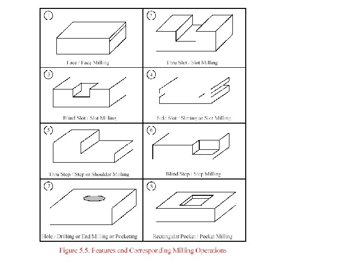
PRODUCT REPRESENTATION Geometrical information Part shape Design features Technological information Tolerances Surface quality (surface finish, surface integrity) Special manufacturing notes Etc. "Feature information" Manufacturing features e. g. slots, holes, pockets, etc.

INPUT REPRESENTATION SELECTION • How much information is needed? • Data format required. • Ease of use for the planning. • Interface with other functions, such as, part programming, design, etc. • Easy recognition of manufacturing features. • Easy extraction of planning information from the representation.

WHAT INPUT REPRESENTATIONS GT CODE Line drawing Special language Symbolic representation Solid model CSG B-Rep others? Feature based model

SPECIAL LANGUAGE

CIMS/PRO REPRESENTATION

2 w 6 1 d 5 l 4 3
/10, if >600 then 600 **hol=25, STP=(ix 10)/7 Depth T-SLT ;")
Area ; (Real area)/10, if >600 then 600 **hol=25, STP=(ix 10)/7 Depth T-SLT ; (min=160, i+160), PKT. STP=240, Face=400 Direction ; Face = 200, if operation >2 = 160 otherwise 120

BACKWARD PLANNING

CONCEPT OF FEATURE Manufacturing is "feature" based. Feature: 1 a: the structure, form, or appearance esp. of a person b: physical beauty. 2 a: the makeup or appearance of the face or its parts b: a part of the face: LINEAMENT 3: a prominent part or characteristic 4: a special attraction

Product feature

FEATURES IN DESIGN AND MANUFACTURING A high level geometry which includes a set of connected geometries. Its meaning is dependent upon the application domain. Design Feature vs Manufacturing Feature

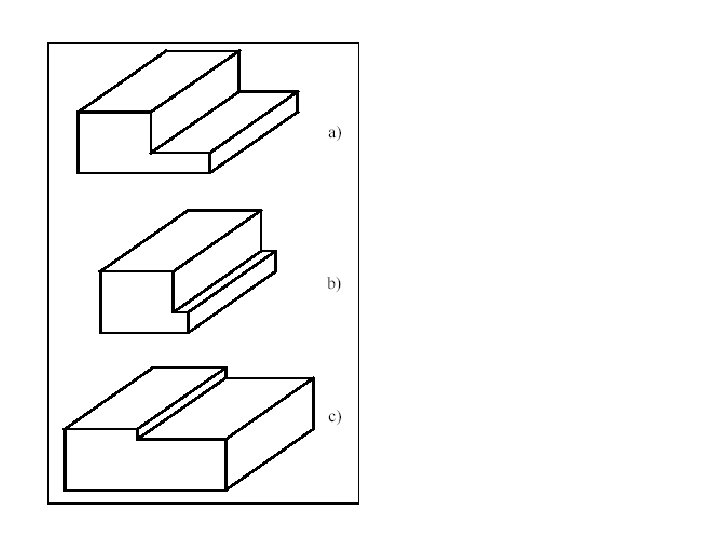
DESIGN FEATURES • For creating a shape • For providing a function Slot feature

MANUFACTURING FEATURES • For process selection • For fixturing End mill a slot Manufacturing is feature based. Drilling Round hole Turning End milling Rotational feature Plane surface, Hole, profile, slot pocket Free form surface Cylindrical shell. . . Ball end mill Boring Reaming. . .
 ?")
MANUFACTURING FEATURES (cont. ) ?

A FEATURE BASED DESIGN/ PROCESS PLANNING SYSTEM Manufacturing-Oriented Design Features hole, straight slot, T-slot, circular slot, pocket counterbore, sculptured surface cavity Geometric Reasoning Application-Specific Features (e. g. manufacturing features) blind slot, through slot, step, etc. approach direction, feed direction feature relations: precedence and intersection type Principle: Provide designer with the freedom to describe shape -

THE DEVELOPMENT OF CAPP

Research Trend in CAPP • Integration with Product Design – Design of Manufacturing, Design for Assembly – Sequential Product Development Process • Integration with PPC – Optimization of total Production Time • Distributed CAPP – Holonic Manufacturing, AI

Questions? !?
- Slides: 106