
Managing Computer and Communication Networks Part 2 Dr





- Slides: 47
Managing Computer and Communication Networks Part 2 Dr. Hamid Reza Naji
Data link Layer The concerns at the Data Link Layer include: 1. 2. 3. 4. What services should be provided to upper layers? Framing, Error Control. Flow Control. 2
Data link Layer The goal of the data link layer is to provide reliable, efficient communication between adjacent machines connected by a single communication channel. Specifically: 1. Group the physical layer bit stream into units called frames. Note that frames are nothing more than "packets" or "messages". By convention, we'll use the term "frames" when discussing DLL packets. 2. Sender checksums the frame and transmits checksum together with data. The checksum allows the receiver to determine when a frame has been damaged in transit. 3. Receiver re-computes the checksum and compares it with the received value. If they differ, an error has occurred and the frame is discarded. 3
Data link Layer 4. Perhaps return a positive or negative acknowledgment to the sender. A positive acknowledgment indicate the frame was received without errors, while a negative acknowledgment indicates the opposite. 5. Flow control. Prevent a fast sender from overwhelming a slower receiver. For example, a supercomputer can easily generate data faster than a PC can consume it. 6. In general, provide service to the network layer. The network layer wants to be able to send packets to its neighbors without worrying about the details of getting it there in one piece. The above is what the OSI reference model suggests. 4
SERVICES PROVIDED TO THE NETWORK LAYER Unacknowledged Connection-less Service -- Best Effort: The receiver does not return acknowledgments to the sender, so the sender has no way of knowing if a frame has been successfully delivered. When would such a service be appropriate? When higher layers can recover from errors with little loss in performance. That is, when errors are so infrequent that there is little to be gained by the data link layer performing the recovery. It is just as easy to have higher layers deal with occasional lost packets. 5
SERVICES PROVIDED TO THE NETWORK LAYER Acknowledged Connection-less Service -- Acknowledged Delivery: • The receiver returns an acknowledgment frame to the sender indicating that a data frame was properly received. The sender keeps connection state, but may not necessarily retransmit unacknowledged frames. • Likewise, the receiver may hand received frames to higher layers in the order in which they arrive, regardless of the original sending order. • Typically, each frame is assigned a unique sequence number, which the receiver returns in an acknowledgment frame to indicate which frame the ACK refers to. The sender must retransmit unacknowledged (e. g. , lost or damaged) frames. 6
SERVICES PROVIDED TO THE NETWORK LAYER Acknowledged Connection-Oriented Service -- Reliable Delivery: • Frames are delivered to the receiver reliably and in the same order as generated by the sender. • Connection state keeps track of sending order and which frames require retransmission. For example, receiver state includes which frames have been received, which ones have not, etc. 7
FRAMING The DLL translates the physical layer's raw bit stream into discrete units (messages) called frames. How can frame be transmitted so the receiver can detect frame boundaries? That is, how can the receiver recognize the start and end of a frame? We will discuss four ways: • Character Count • Bit Stuffing • Character stuffing • Encoding Violations 8
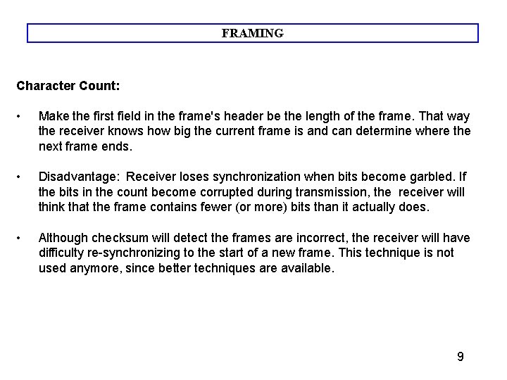
FRAMING Character Count: • Make the first field in the frame's header be the length of the frame. That way the receiver knows how big the current frame is and can determine where the next frame ends. • Disadvantage: Receiver loses synchronization when bits become garbled. If the bits in the count become corrupted during transmission, the receiver will think that the frame contains fewer (or more) bits than it actually does. • Although checksum will detect the frames are incorrect, the receiver will have difficulty re-synchronizing to the start of a new frame. This technique is not used anymore, since better techniques are available. 9
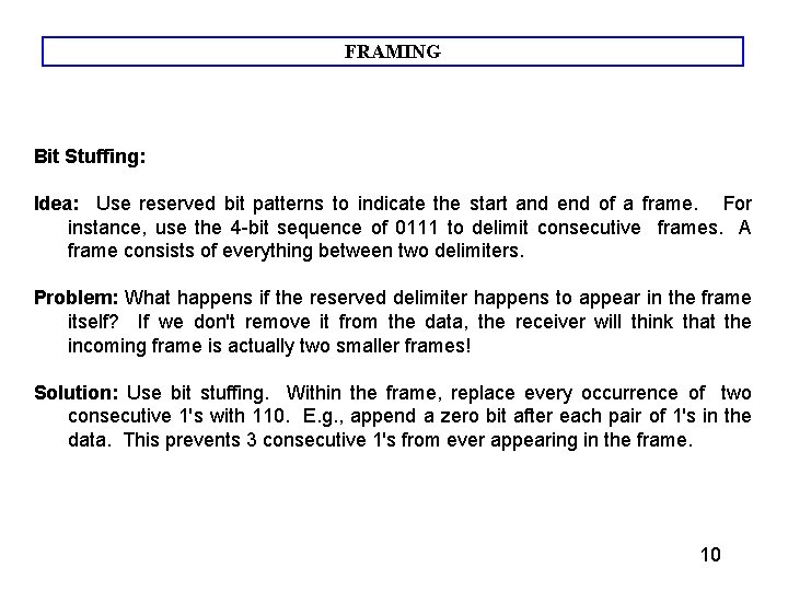
FRAMING Bit Stuffing: Idea: Use reserved bit patterns to indicate the start and end of a frame. For instance, use the 4 -bit sequence of 0111 to delimit consecutive frames. A frame consists of everything between two delimiters. Problem: What happens if the reserved delimiter happens to appear in the frame itself? If we don't remove it from the data, the receiver will think that the incoming frame is actually two smaller frames! Solution: Use bit stuffing. Within the frame, replace every occurrence of two consecutive 1's with 110. E. g. , append a zero bit after each pair of 1's in the data. This prevents 3 consecutive 1's from ever appearing in the frame. 10
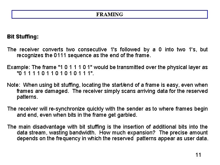
FRAMING Bit Stuffing: The receiver converts two consecutive 1's followed by a 0 into two 1's, but recognizes the 0111 sequence as the end of the frame. Example: The frame "1 0 1 1 1 0 1" would be transmitted over the physical layer as "0 1 1 0 1 0 1 1 1". Note: When using bit stuffing, locating the start/end of a frame is easy, even when frames are damaged. The receiver simply scans arriving data for the reserved patterns. The receiver will re-synchronize quickly with the sender as to where frames begin and end, even when bits in the frame get garbled. The main disadvantage with bit stuffing is the insertion of additional bits into the data stream, wasting bandwidth. How much expansion? The precise amount depends on the frequency in which the reserved patterns appear as user data. 11
FRAMING Character stuffing: Same idea as bit-stuffing, but operates on bytes instead of bits. Use reserved characters to indicate the start and end of a frame. For instance, use the two-character sequence DLE STX (Data-Link Escape, Start of Te. Xt) to signal the beginning of a frame, and the sequence DLE ETX (End of Te. Xt) to flag the frame's end. Problem: What happens if the two-character sequence DLE ETX happens to appear in the frame itself? Solution: Use character stuffing within the frame, replace every occurrence of DLE with the two-character sequence DLE. The receiver reverses the process, replacing every occurrence of DLE with a single DLE. Example: If the frame contained "A B DLE D E DLE", the characters transmitted over the channel would be "DLE STX A B DLE D E DLE DLE ETX". Disadvantage: A byte is the smallest unit that can be operated on; not all architectures are 8 -bit oriented. 12
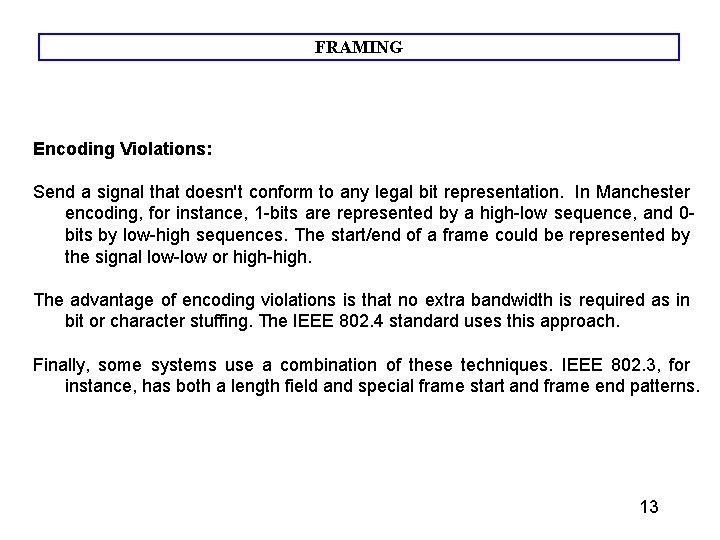
FRAMING Encoding Violations: Send a signal that doesn't conform to any legal bit representation. In Manchester encoding, for instance, 1 -bits are represented by a high-low sequence, and 0 bits by low-high sequences. The start/end of a frame could be represented by the signal low-low or high-high. The advantage of encoding violations is that no extra bandwidth is required as in bit or character stuffing. The IEEE 802. 4 standard uses this approach. Finally, some systems use a combination of these techniques. IEEE 802. 3, for instance, has both a length field and special frame start and frame end patterns. 13
ERROR CONTROL Must insure that all frames are eventually delivered (possibly in order) to a destination. Three components are required to do this: Acknowledgments, Timers, and Sequence Numbers Acknowledgments: • Reliable delivery is achieved using the "acknowledgments with retransmission" paradigm. • The receiver returns a special acknowledgment (ACK) frame to the sender indicating the correct receipt of a frame. • In some systems, the receiver also returns a negative acknowledgment (NACK) for incorrectly-received frames. • This is only a hint to the sender so that it can retransmit a frame right away without waiting for a timer to expire. 14
ERROR CONTROL Timers: • • • One problem that simple ACK/NACK schemes fail to address is recovering from a frame that is lost, and as a result, fails to solicit an ACK or NACK. What happens if an ACK or NACK becomes lost? Retransmission timers are used to resend frames that don't produce an ACK. When sending a frame, schedule a timer to expire at some time after the ACK should have been returned. If the timer goes off, retransmit the frame. Sequence Numbers: • • • Retransmissions introduce the possibility of duplicate frames. To suppress duplicates, add sequence numbers to each frame, so that a receiver can distinguish between new frames and repeats of old frames. Bits used for sequence numbers depend on the number of frames that can be outstanding at any one time. 15
ERROR CONTROL Flow control deals with throttling the speed of the sender to match that of the receiver. Usually, this is a dynamic process, as the receiving speed depends on such changing factors as the load, and availability of buffer space. One solution is to have the receiver extend credits to the sender. For each credit, the sender may send one frame. Thus, the receiver controls the transmission rate by handing out credits. LINK INITIALIZATION: In some cases, the data link layer service must be "opened" before use: The data link layer uses open operations for allocating buffer space, control blocks, agreeing on the maximum message size, etc. Synchronize and initialize send and receive sequence numbers with its peer at the other end of the communications channel. 16
ERROR CORRECTING CODES In data communication, line noise is a fact of life (e. g. , signal attenuation, natural phenomenon such as lightning, and the telephone worker). Moreover, noise usually occurs as bursts rather than independent, single bit errors. For example, a burst of lightning will affect a set of bits for a short time after the lightning strike. Detecting and correcting errors requires redundancy - sending additional information along with the data. 17
ERROR CORRECTING CODES There are two types of attacks against errors: Error Detecting Codes: Include enough redundancy bits to detect errors and use ACKs and retransmissions to recover from the errors. Error Correcting Codes: Include enough redundancy to detect and correct errors. We will introduce some concepts, and then consider both detection and correction. To understand errors, consider the following: Messages (frames) consist of m data (message) bits and r redundancy bits, yielding an n = ( m + r ) bit codeword 18
ERROR CORRECTING CODES Hamming Distance. Given any two codewords, we can determine how many of the bits differ. Simply exclusive or (XOR) the two words, and count the number of 1 bits in the result. This count is the Hamming Distance. Significance? If two codewords are d bits apart, d errors are required to convert one to the other. A code's Hamming Distance is defined as the minimum Hamming Distance between any two of its legal codewords (from all possible codewords). In general, all 2 m possible data words are legal. However, by choosing check bits carefully, the resulting codewords will have a large Hamming Distance. The larger the Hamming distance, the better the codes are able to detect errors. To detect d 1 -bit errors requires having a Hamming Distance of at least d + 1 bits. Why? To correct d errors requires 2 d + 1 bits. Intuitively, after d errors, the garbled messages is still closer to the original message than any other legal codeword. 19
ERROR CORRECTING CODES Parity Bits A single parity bit is appended to each data block (e. g. each character in ASCII systems) so that the number of 1 bits always adds up to an even (odd) number. 1000000(1) 1111101(0) The Hamming Distance for parity is 2, and it cannot correct even single-bit errors (but can detect single-bit errors). As another example, consider a 10 -bit code used to represent 4 possible values: "00000 00000", "00000 11111", "11111 00000", and "11111 11111". Its Hamming distance is 5, and we can correct 2 single-bit errors: For instance, "10111 00010" becomes "11111 00000" by changing only two bits. However, if the sender transmits "11111 00000" and the receiver sees "00011 00000", the receiver will not correct the error properly. 20
ERROR CORRECTION What's the fewest number of bits needed to correct single bit errors? Let us design a code containing n = m + r bits that corrects all single-bit errors (remember m is the number of message (data) bits and r is number of redundant (check) bits): There are 2 m legal messages (e. g. , legal bit patterns). Each of the m messages has n illegal codewords a distance of 1 from it. That is, if we systematically invert each bit in the corresponding n-bit codeword, we get illegal codewords a distance of 1 from the original. Thus, each message requires n + 1 bits dedicated to it (n that are one bit away and 1 that is the message). The total number of bit patterns is ( n + 1 ) * 2 m < 2 n. That is, all (n+1) * 2 m encoded messages should be unique, and there can't be fewer messages than the 2 n possible code-words. Since n = m + r , we get: ( m + r + 1) * 2 m < 2 m+r or ( m + r + 1) < 2 r This formula gives the absolute lower limit on the number of bits required to detect (and 21 correct!) 1 -bit errors.
ERROR DETECTION Error correction is relatively expensive (computationally and in bandwidth. ) For example, 10 redundancy bits are required to correct 1 single-bit error in a 1000 -bit message. In contrast, detecting a single bit error requires only a single-bit, no matter how large the message. The most popular error detection codes are based on polynomial codes or cyclic redundancy codes(CRCs). Allows us to acknowledge correctly received frames and to discard incorrect ones. 22
DLL Protocols How can two DLL layers communicate in order to assure reliability? We will look at increasingly complex protocols to see how this is done. 23
DLL Protocols ELEMENTARY DATA LINK PROTOCOLS: The DLL provides these services to the Network Layer above it: Data handed to a DLL by a Network Layer on one module, are handed to the Network Layer on another module by that DLL. The remote Network Layer peer should receive the identical message generated by the sender (e. g. , if the data link layer adds control information, the header information must be removed before the message is passed to the Network Layer). The Network Layer may want to be sure that all messages it sends, will be delivered correctly (e. g. , none lost, no corruption). Note that arbitrary errors may result in the loss of both data and control frames. 24
DLL Protocols ELEMENTARY DATA LINK PROTOCOLS: The Network Layer may want messages to be delivered to the remote peer in the exact same order as they are sent. Note: It is not always clear that we really want our data link layer protocol to provide this type of service. What if we run real-time applications across the link? Nonetheless, the ISO reference model suggests that the data link layer provide such a service, and we now examine the protocols that do so. THE METHOD WE WILL USE: Look at successive data link protocols of increasing complexity to provide reliable, in order, message delivery to the network layer. 25
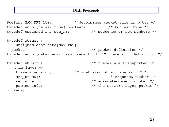
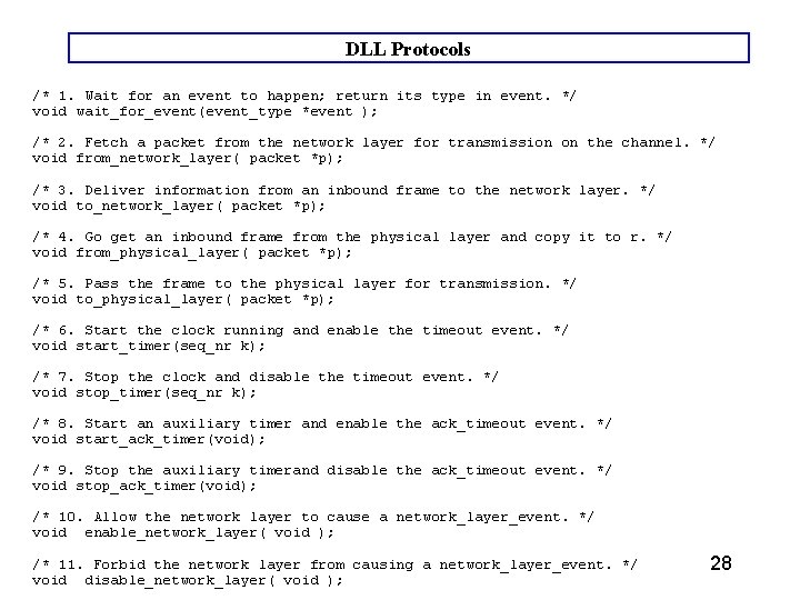
DLL Protocols Environment: Assume DLL executes as a process (scheduleable entity) with routines to communicate with the Network Layer above and the Physical Layer below. Frames are the unit of transmission. Consists of data plus control bits (header information). Look at data structures and prototypes on the next few pages – this is Figure 3. 8. Of special interest is typedef struct frame; void wait_for_event( event_type *event ); wait_for_event() suspends the process until an event occurs. Possible events include requests from the network layer, the physical layer and the timer. 26
DLL Protocols #define MAX PKT 1024 * determines packet size in bytes */ typedef enum {false, true} boolean; /* boolean type */ typedef unsigned int seq_nr; /* sequence or ack numbers */ typedef struct { unsigned char data[MAX PKT]; } packet; /* packet definition */ typedef enum {data, ack, nak} frame_kind; /* frame kind definition */ typedef struct { this layer */ frame_kind; seq_nr seq; seq_nr ack; packet info; } frame; /* frames are transported in /* what kind of a frame is it? */ /* sequence number */ /* acknowledgement number */ /* the network layer packet */ 27
DLL Protocols /* 1. Wait for an event to happen; return its type in event. */ void wait_for_event(event_type *event ); /* 2. Fetch a packet from the network layer for transmission on the channel. */ void from_network_layer( packet *p); /* 3. Deliver information from an inbound frame to the network layer. */ void to_network_layer( packet *p); /* 4. Go get an inbound frame from the physical layer and copy it to r. */ void from_physical_layer( packet *p); /* 5. Pass the frame to the physical layer for transmission. */ void to_physical_layer( packet *p); /* 6. Start the clock running and enable the timeout event. */ void start_timer(seq_nr k); /* 7. Stop the clock and disable the timeout event. */ void stop_timer(seq_nr k); /* 8. Start an auxiliary timer and enable the ack_timeout event. */ void start_ack_timer(void); /* 9. Stop the auxiliary timerand disable the ack_timeout event. */ void stop_ack_timer(void); /* 10. Allow the network layer to cause a network_layer_event. */ void enable_network_layer( void ); /* 11. Forbid the network layer from causing a network_layer_event. */ void disable_network_layer( void ); 28
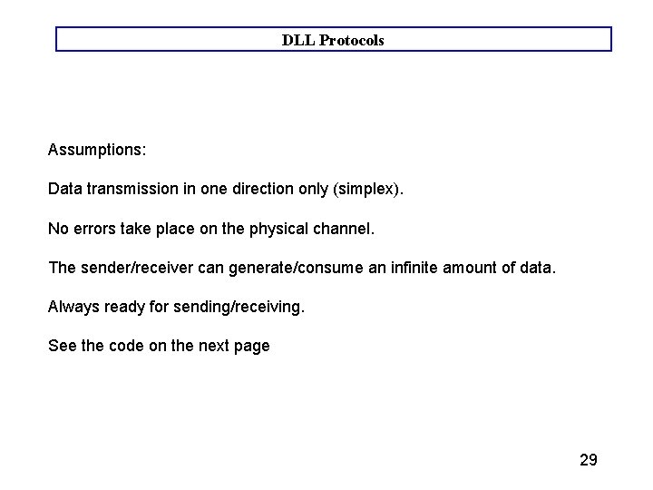
DLL Protocols Assumptions: Data transmission in one direction only (simplex). No errors take place on the physical channel. The sender/receiver can generate/consume an infinite amount of data. Always ready for sending/receiving. See the code on the next page 29
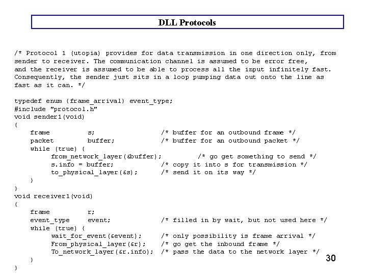
DLL Protocols /* Protocol 1 (utopia) provides for data transmission in one direction only, from sender to receiver. The communication channel is assumed to be error free, and the receiver is assumed to be able to process all the input infinitely fast. Consequently, the sender just sits in a loop pumping data out onto the line as fast as it can. */ typedef enum {frame_arrival} event_type; #include "protocol. h" void sender 1(void) { frame s; /* buffer for an outbound frame */ packet buffer; /* buffer for an outbound packet */ while (true) { from_network_layer(&buffer); /* go get something to send */ s. info = buffer; /* copy it into s for transmission */ to_physical_layer(&s); /* send it on its way */ } } void receiver 1(void) { frame r; event_type event; /* filled in by wait, but not used here */ while (true) { wait_for_event(&event); /* only possibility is frame arrival */ From_physical_layer(&r); /* go get the inbound frame */ To_network_layer(&r. info); /* pass the data to the network layer */ 30 } }
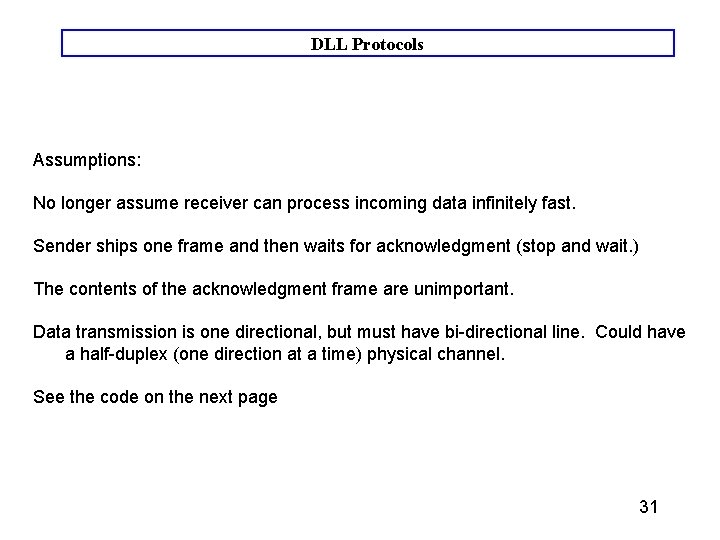
DLL Protocols Assumptions: No longer assume receiver can process incoming data infinitely fast. Sender ships one frame and then waits for acknowledgment (stop and wait. ) The contents of the acknowledgment frame are unimportant. Data transmission is one directional, but must have bi-directional line. Could have a half-duplex (one direction at a time) physical channel. See the code on the next page 31
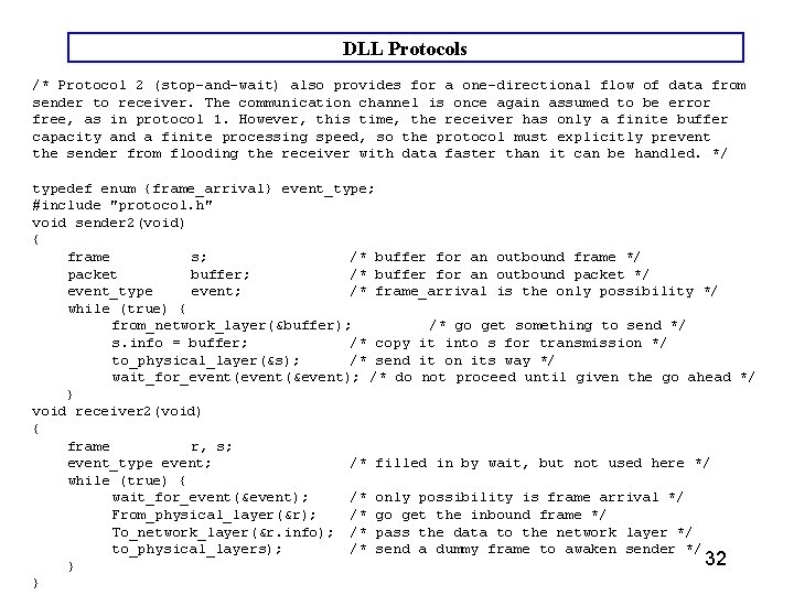
DLL Protocols /* Protocol 2 (stop-and-wait) also provides for a one-directional flow of data from sender to receiver. The communication channel is once again assumed to be error free, as in protocol 1. However, this time, the receiver has only a finite buffer capacity and a finite processing speed, so the protocol must explicitly prevent the sender from flooding the receiver with data faster than it can be handled. */ typedef enum {frame_arrival} event_type; #include "protocol. h" void sender 2(void) { frame s; /* buffer for an outbound frame */ packet buffer; /* buffer for an outbound packet */ event_type event; /* frame_arrival is the only possibility */ while (true) { from_network_layer(&buffer); /* go get something to send */ s. info = buffer; /* copy it into s for transmission */ to_physical_layer(&s); /* send it on its way */ wait_for_event(&event); /* do not proceed until given the go ahead */ } void receiver 2(void) { frame r, s; event_type event; /* filled in by wait, but not used here */ while (true) { wait_for_event(&event); /* only possibility is frame arrival */ From_physical_layer(&r); /* go get the inbound frame */ To_network_layer(&r. info); /* pass the data to the network layer */ to_physical_layers); /* send a dummy frame to awaken sender */ 32 } }
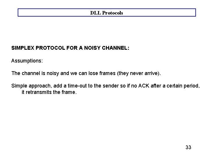
DLL Protocols SIMPLEX PROTOCOL FOR A NOISY CHANNEL: Assumptions: The channel is noisy and we can lose frames (they never arrive). Simple approach, add a time-out to the sender so if no ACK after a certain period, it retransmits the frame. 33
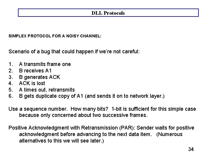
DLL Protocols SIMPLEX PROTOCOL FOR A NOISY CHANNEL: Scenario of a bug that could happen if we’re not careful: 1. A transmits frame one 2. B receives A 1 3. B generates ACK 4. ACK is lost 5. A times out, retransmits 6. B gets duplicate copy of A 1 (and sends it on to network layer. ) Use a sequence number. How many bits? 1 -bit is sufficient for this simple case because only concerned about two successive frames. Positive Acknowledgment with Retransmission (PAR): Sender waits for positive acknowledgment before advancing to the next data item. (Numerous alternatives to this we will see later. ) 34
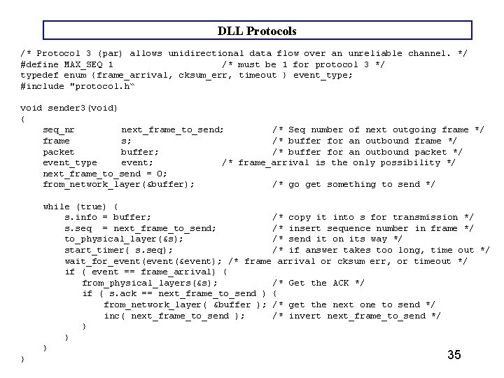
DLL Protocols /* Protocol 3 (par) allows unidirectional data flow over an unreliable channel. */ #define MAX_SEQ 1 /* must be 1 for protocol 3 */ typedef enum {frame_arrival, cksum_err, timeout } event_type; #include "protocol. h“ void sender 3(void) { seq_nr next_frame_to_send; /* Seq number of next outgoing frame */ frame s; /* buffer for an outbound frame */ packet buffer; /* buffer for an outbound packet */ event_type event; /* frame_arrival is the only possibility */ next_frame_to_send = 0; from_network_layer(&buffer); /* go get something to send */ while (true) { s. info = buffer; /* copy it into s for transmission */ s. seq = next_frame_to_send; /* insert sequence number in frame */ to_physical_layer(&s); /* send it on its way */ start_timer( s. seq); /* if answer takes too long, time out */ wait_for_event(&event); /* frame arrival or cksum err, or timeout */ if ( event == frame_arrival) { from_physical_layers(&s); /* Get the ACK */ if ( s. ack == next_frame_to_send ) { from_network_layer( &buffer ); /* get the next one to send */ inc( next_frame_to_send ); /* invert next_frame_to_send */ } } 35
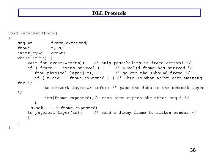
DLL Protocols void receiver 3(void) { seq_nr frame_expected; frame r, s; event_type event; while (true) { wait_for_event(&event); /* only possibility is frame arrival */ if ( frame == event_arrival ) { /* A valid frame has arrived */ from_physical_layer(&r); /* go get the inbound frame */ if ( r. seq == frame_expected ) { /* This is what we’ve been waiting for */ to_network_layer(&r. info); /* pass the data to the network layer */ inc(frame_expected); /* next time expect the other seq # */ } s. ack = 1 – frame_expected; to_physical_layer(&s); /* send a dummy frame to awaken sender */ } } } 36
DLL Protocols A Problem unresolved by this protocol is this: How long should the timer be? What if too long? (inefficient) What if too short? A problem because the ACK does not contain the sequence number of the frame which is being ACK'd. So, which frame is being ACK’d? 37
DLL Protocols Scenario: A sends frame A 0 time out of A resend frame A 0 B receives A 0, ACKS B receives A 0 again, ACKS again (does not accept) A gets A 0 ACK, sends frame A 1 gets lost A gets second A 0 ACK (assumes it’s ACK of A 1), sends A 2 B gets A 2 (rejects, not correct seq. number) Will lose two frames before getting back on track (with A 3) 38
DLL Protocols Sliding Window Protocols Assumptions: Use more realistic Two-way communication. We now have two kinds of frames (containing a "kind" field): 1. Data 2. ACK containing (sequence number of last correctly received frame). Piggybacking - add acknowledgment to data frames going in reverse direction.
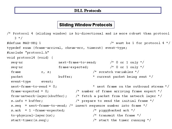
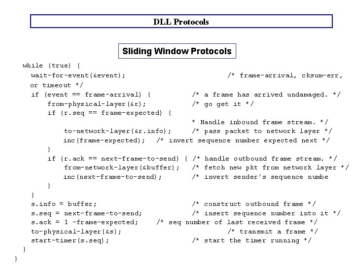
DLL Protocols Sliding Window Protocols Example of a sliding window protocol. Contains a sequence number whose maximum value, Max. Seq, is 2 n - 1. For stop-and-wait sliding window protocol, n = 1. Essentially same as Simplex Protocol, except ACKs are numbered, which solves early time out problem. Two-way communication. Protocol works, all frames delivered in correct order. Requires little buffer space. Poor line utilization due to stop-and-wait. (To be solved in next example. )
DLL Protocols Sliding Window Protocols /* Protocol 4 (sliding window) is bi-directional and is more robust than protocol 3 */ #define MAX-SEQ 1 /* must be 1 for protocol 4 */ typedef enum {frame-arrival, cksum-err, timeout} event-type; #include "protocol. h" void protocol 4 (void) { seq-nr next-frame-to-send; /* 0 or 1 only */ seq-nr frame-expected; /* 0 or 1 only */ frame r, s; /* scratch variables */ packet buffer; * current packet being sent */ event-type event; next-frame-to-send = 0; * next frame on the outbound stream */ frame-expected = 0; /* number of frame arriving frame expect */ from-network-layer(&buffer); /* fetch a packet from the network layer */ s. info = buffer; /* prepare to send the initial frame */ s. seq = next-frame-to-send; /* insert sequence number into frame */ s. ack = 1 -frame-expected; /* piggybacked ack */ to-physical-layer(&s); /* transmit the frame */ start-timer(s. seq); /* start the timer running */
DLL Protocols Sliding Window Protocols while (true) { wait-for-event(&event); or timeout */ if (event == frame-arrival) { from-physical-layer(&r); if (r. seq == frame-expected) { /* frame-arrival, cksum-err, /* a frame has arrived undamaged. */ /* go get it */ * Handle inbound frame stream. */ to-network-layer(&r. info); /* pass packet to network layer */ inc(frame-expected); /* invert sequence number expected next */ } if (r. ack == next-frame-to-send) { /* handle outbound frame stream. */ from-network-layer(&buffer); /* fetch new pkt from network layer */ inc(next-frame-to-send); /* invert sender's sequence numbe } } s. info = buffer; s. seq = next-frame-to-send; s. ack = 1 -frame-expected; to-physical-layer(&s); start-timer(s. seq); } } /* construct outbound frame */ /* insert sequence number into it */ /* seq number of last received frame */ /* transmit a frame */ /* start the timer running */
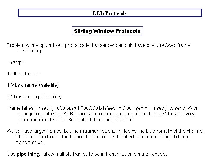
DLL Protocols Sliding Window Protocols Problem with stop and wait protocols is that sender can only have one un. ACKed frame outstanding. Example: 1000 bit frames 1 Mbs channel (satellite) 270 ms propagation delay Frame takes 1 msec ( 1000 bits/(1, 000 bits/sec) = 0. 001 sec = 1 msec ) to send. With propagation delay the ACK is not seen at the sender again until time 541 msec. Very poor channel utilization. Several solutions are possible: We can use larger frames, but the maximum size is limited by the bit error rate of the channel. The larger the frame, the higher the probability that it will become damaged during transmission. Use pipelining: allow multiple frames to be in transmission simultaneously.
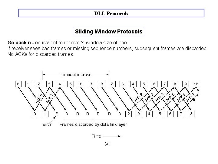
DLL Protocols Sliding Window Protocols Sender does not wait for each frame to be ACK'ed. Rather it sends many frames with the assumption that they will arrive. Must still get back ACKs for each frame. Provides more efficient use of transmit bandwidth, but error handling is more complex. What if 20 frames transmitted, and the second has an error. Frames 3 -20 will be ignored at receiver side? Sender will have to retransmit. What are the possibilities? Two strategies for receive Window size:
DLL Protocols Sliding Window Protocols Go back n - equivalent to receiver's window size of one. If receiver sees bad frames or missing sequence numbers, subsequent frames are discarded. No ACKs for discarded frames.
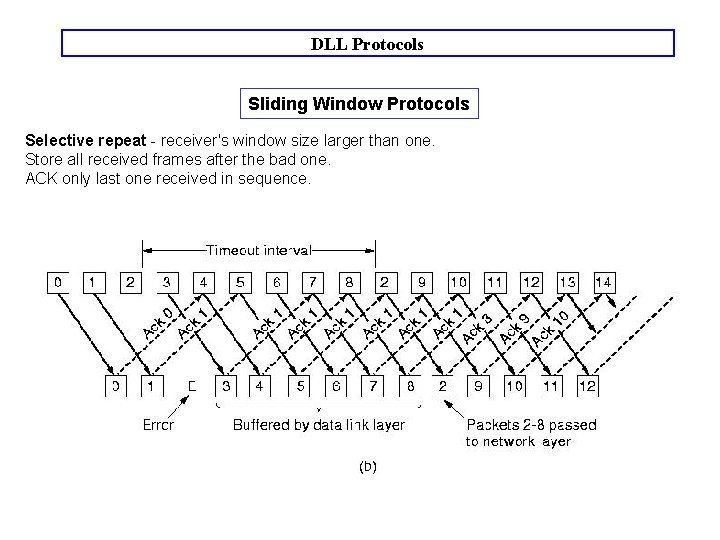
DLL Protocols Sliding Window Protocols Selective repeat - receiver's window size larger than one. Store all received frames after the bad one. ACK only last one received in sequence.
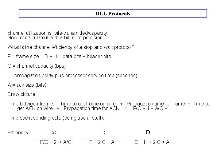
DLL Protocols channel utilization is bits-transmitted/capacity. Now let calculate it with a bit more precision: What is the channel efficiency of a stop-and-wait protocol? F = frame size = D + H = data bits + header bits C = channel capacity (bps) I = propagation delay plus processor service time (seconds) A = ack size (bits) Draw picture Time between frames: Time to get frame on wire + Propagation time for frame + Time to get ACK on wire + Propagation time for ACK = F/C + I + A/C + I Time spent sending data (doing useful stuff): Efficiency: D/C D --------------------- = --------------- F/C + 2 I + A/C F + 2 IC + A D + H + 2 IC + A