Major Connectors Components of a typical removable partial

Major Connectors

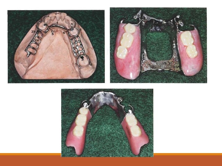
Components of a typical removable partial dentures 1. Major connectors 2. Minor connectors 3. Rests 4. Direct retainers 5. Stabilizing or reciprocal components (as parts of a clasp assembly) 6. Indirect retainers (if the prosthesis has distal extension bases) 7. One or more bases, each supporting one to several replacement teeth

The chief functions of a major connector include unification of the major parts of the prosthesis, distribution of the applied force throughout the arch to selected teeth and tissue, and minimization of torque to the teeth.

This component also provides the cross-arch stability to help resist displacement by functional stresses.

Location 1. Major connectors should be free of movable tissue. 2. Impingement of gingival tissue should be avoided. 3. Bony and soft tissue prominences should be avoided during placement and removal. 4. Relief should be provided beneath a major connector to prevent its settling into areas of possible interference, such as inoperable tori or elevated median palatal sutures.

Major connectors should be located and/or relieved to prevent impingement of tissue because the distal extension denture rotates in function.

§DEFINITION § A MAJOR CONNECTOR IS THE COMPONENT OF THE PARTIAL DENTURE THAT CONNECTS THE PARTS OF THE PROSTHESIS LOCATED ON ONE SIDE OF THE ARCH WITH THOSE ON THE OPPOSITE SIDE. § It is that unit of the partial denture to which all other parts are directly or indirectly attached

CONTENTS §Function of the major connector §Desirable characteristics of major connector §Types of major connector §Steps in designing major connector §Metarial used for major connector §Factors affecting the selection of major connector

DESIRABLE CHARACTERISTICS OF MAJOR CONNECTORS 1. Rigid 2. Compatible with oral tissues 3. Does not interfere with and is not irritating to the tongue 4. Does not substantially alter the natural contour of the palatal vault. 5. Does not impinge on oral tissues 6. Covers no more tissue than is absolutely necessary 7. Does not contribute to the retention or trapping of food particles. 8. Contribute to the support of the prosthesis.

TYPES OF MAJOR CONNECTOR SIX BASIC TYPES OF MAXILLARY MAJOR CONNECTORS ARE CONSIDERED: 1. SINGLE PALATAL BAR 2. SINGLE PALATAL STRAP 3. U-SHAPED PALATAL CONNECTOR 4. ANTERIOR-POSTERIOR PALATAL BAR 5. COMBINATION ANTERIOR AND POSTERIOR PALATAL STRAP-TYPE CONNECTOR 6. PALATAL PLATE-TYPE CONNECTOR

SINGLE PALATAL BAR §A palatal connector component of less than 8 mm in width is referred to as a bar. §It is narrow half – oval with its thickest point at the centre

§A partial denture made with a single palatal bar is often either too thin and flexible or too bulky and objectionable to the patient's tongue INDICATION §Limited to replacing one or two teeth on each side of arch and placed no further anteriorly than the second premolar position. §Perhaps the only indication for its use is as an interim partial denture until a more definitive treatment can be considered. CONTRAINDICATION § In distal extension situation § when anterior teeth are to be replaced

DISADVANTAGES § Most difficult for the patient to adjust as to maintain the degree of rigidity it has to be made bulky. § Due its narrow anterior-posterior width it derives little vertical support from the bony palate and must be therefore supported positively by rests on the remaining natural teeth.

SINGLE PALATAL STRAP §It consists of a wide thin barel of metal that crosses the palate in an unobtrusive manner. § It should not be less than 8 mm wide or its rigidity maybe compromised. §It can be relatively narrow for small tooth supported prosthesis or wider for larger edentulous spaces requiring support

§ADVANTAGES § Because the palatal strap is located in three planes it offers great resistance to bending and twisting forces. §Distribution of stress over a broad area. §Retention of the partial denture is enhanced by the intimate contact between the metal and soft tissue. §The strap also contributes some indirect retention.

§DISADVANTAGES §The patient may complain of excessive palatal coverage. §Another possible disadvantage is an adverse soft tissue reaction in the form of papillary hyperplasia. §INDICATIONS §Used only when 1 or 2 teeth are being replaced on either side. §In CLASS III situations §Need for palatal support is minimal §CONTRAINDICATION § Anterior replacements with distal extension bases.

§U-SHAPED PALATAL CONNECTOR §It consists of thin band of metal running along posterior teeth and extending onto the palatal tissues for 6 -8 mm. §The borders of the horseshoe connector must either be 6 mm from the gingival margin or extend onto the lingual surfaces of the teeth. §The borders should also be placed in the valleys of the rugae. §The lateral palatal borders should be at the junction of the horizontal and vertical slopes of the palate.

§The rigidity can be increased by extending the borders slightly onto the horizontal palate surface. INDICATIONS • Can be in case of a large inoperable tori • When several anterior teeth are to be replaced. • In case of patients with exaggerated gag reflex. • When periodontically weakened anterior teeth need some stabilizing support.

§DISADVANTAGES §Its lack of rigidity allows lateral flexure under occlusal forces… induce torque or direct lateral force to abutment teeth. §Bulk to enhance rigidity results in increased thickness in areas that are a hindrance to the tongue.

§ANTERIOR AND POSTERIOR PALATAL BAR-TYPE CONNECTORS § The flat anterior bar is narrower than the palatal strap…borders are positioned in the valleys between the rugae. §The posterior bar is half-oval, similar to the single posterior palatal bar connector but less bulky. §The two bars are joined by flat longitudinal elements on each side of the lateral slopes of the palate providing an L beam effect

§INDICATIONS §when support is not a major consideration and when the anterior and posterior abutments are widely separated. §Presence of torus palatinus. §The patient's mental attitude: the a-p bar may be used as a compromise for the patient who strongly objects to the greater bulk or area coverage of the full palatal connector. CONTRAINDICATIONS In reduced periodontal support of the remaining teeth that necessitates additional support from the palate.

§ADVANTAGES §The main advantage is its rigidity. In comparison to the amount of soft tissue coverage, it is by far the most rigid maxillary major connector §DISADVANTAGES §it is frequently uncomfortable. §Derive very little support from the palate. §May interfere with speech- especially the anterior bar.

§ANTERIOR AND POSTERIOR PALATAL STRAP-TYPE CONNECTOR §A posterior palatal strap should be flat and a minimum of 8 mm wide. § Posterior palatal connectors should be located as far posteriorly as possible to avoid interference with the tongue

§INDICATIONS §Kennedy’s Class I and CLASS II arches. §CLASS II modifications I arches. §Class IV arches. §In case of inoperable tori. §DISADVANTAGES §Even though the metal over thin rugae area may be thinner than in some other major connectors, interference with phonetics may occur in some patients. §In addition, the extensive length of borders may cause discomfort to the tongue

§PALATAL PLATE-TYPE CONNECTOR §The full palate connector should be thin, with the natural anatomy of the palate reproduced. . §The anterior border must be kept 6 mm from the marginal gingiva or must cover the cingula of the anterior teeth. § The posterior border of the complete palate normally extends to the juncture of the soft and hard palate. §The posterior border can be fabricated of either metal or acrylic resin.

§If it is made of metal, the border must be precisely established, because if overextended it will quickly induce soreness, and the metal is difficult to alter satisfactorily. §A slight bead should be provided in the metal by lightly scraping the refractory cast, prior to forming the wax pattern for the framework. §The acrylic resin border is preferred when maximum adhesion and atmospheric seal is needed

§ADVANTAGES §It reproduces the anatomic contours properly. §uniform thickness and thermal conductivity of the metal are readily acceptable to the tongue and underlying tissues. §DISADVANTAGES §Adverse soft tissue reaction in the form of inflammation or hyperplasia may occur §Problems with phonetics may occasionally occur

§INDICATIONS §CLASS I AND CLASS II arches §When the last remaining abutment tooth on either side of a Class I arch is the canine or first premolar tooth, §In individuals with a full complement of mandibular teeth §When flat or flabby ridges or a shallow vault is present. §Cleft palate patients §CONTRAINDICATION §Presence of tori which cannot be surgically removed a full palatal coverage cannot be given.

§DESIGN OF MAXILLARY MAJOR CONNECTORS § In 1953 blatterfein described a systematic approach to designing maxillary major connectors. §STEP 1: OUTLINE OF PRIMARY BEARING Areas. The primary bearing areas are those that will be covered by the denture base(s) §STEP 2: OUTLINE OF NONBEARING AREAS. The nonbearing areas are the lingual gingival tissues within 5 to 6 mm of the remaining teeth, hard areas of the medial palatal raphe (including tori), and palatal tissues posterior to the vibrating line.

§STEP 3: OUTLINE OF CONNECTOR AREAS. §STEP 4: SELECTION OF CONNECTOR TYPE §Connectors must have a maximum of rigidity to distribute stress bilaterally. § Connectors should be of minimum bulk §When edentulous areas are located anteriorly, the use of only a posterior strap is not recommended. § By the same token, when only posterior edentulous areas are present, the use of only an anterior strap is not recommended. §The need for indirect retention influences the outline of the major connector. §STEP 5: UNIFICATION. After selection of the type of major connector, the denture base areas and connectors are joined. §

§ MATERIALS USED FOR MAJOR CONNECTORS § THE VARIOUS ALLOYS THAT CAN BE USED IN CONSTRUCTING REMOVABLE PARTIAL DENTURE FRAMEWORK ARE: 1. TYPE IV GOLD ALLOY 2. NICKEL CHROMIUM 3. COBALT-CHROMIUM 4. CO- CR- NI 5. TITANIUM AND ITS ALLOYS

§FACTORS AFFECTING SELECTION OF THE MAXILLARY CONNECTOR §RIGIDITY §THE PRESENCE OF PALATAL TORI §THE NEED FOR ANTERIOR TOOTH REPLACEMENT §THE REQUIREMENT FOR INDIRECT RETENTION §THE NEED TO STABILIZE WEAKENED TEETH §PHONETIC CONSIDERATIONS §THE MENTAL ATTITUDE OF THE PATIENT

Materials used for Major connectors Various alloys that can be used in constructing removable partial denture are: ◦ Type IV gold alloy. ◦ Nickel-chromium. ◦ Cobalt-chromium. ◦ Co-Cr-Ni. ◦ Titanium and its alloys.

Base metal alloys have relatively high elastic modulus. This property suggest that the thickness of partial denture frameworks can be thinner than those of other metals. The ductility of titanium is greater than that of the others. Base metal alloys have higher hardness compared with tooth enamel which causes in vivo wear. Alloys for partial denture frameworks have high melting points and they exhibit high casting shrinkage with potential for casting defects.

Conclusion Major connectors by uniting the other components of a removable partial dentures acts like a foundation bringing about bilateral distribution of forces which depends on the rigidity of the connector. Utmost care should be taken to prevent a major connector from interfering with normal functions or having any damaging effects to the remaining oral structure. Although there are many variations in major connector, a thorough comprehension of all factors influencing their design will lead to the best design for each patient.

References Mc. Cracken’s Removable Partial Prosthodontics. A. B. Carr, G. P. Mc. Givney, D. T. Brown. 11 th edition. Stewart’s Clinical Removable Partial Prosthodontics. Rodney D. Phoenix, David R. Cagna, Charles F. De. Freest. 3 rd edition. Removable partial prosthodontics. Ernest L. Miller, Joseph E. Grasso, Second edition. Bert T. Cecconi : Lingual bar design. J. P. D. 1973; 29: 635 -639. Mc. Cracken W. L. : Contemporary partial denture designs. J. P. D. 2004; 92: 409 -417.

Thank you
- Slides: 38