Mahongruo Gansu Natural Energy Research Institute Table of

Mahongruo Gansu Natural Energy Research Institute

内容大纲 Table of Contents 1 Introduction 6 DESIGN PRINCIPLE 2 Basic principle of focusing 7 MATERIALS 3 Solar cooker in CHINA 8 MANUFACTURINGTECHNIQUES 4 BASIC STRUCTURE 9 TECHNICAL REQUIREMENTS 5 FOCUSING-TYPE 10 OPERATION AND MAINTENANCE
 Soil erosion and ecology")
1. Introduction • Development of solar cooker in China 1) Soil erosion and ecology destroying 2) Rural energy shortage 3) Women and children’s burden *Solar cooker is a device which can concentrates solar energy for cooking.

Fundamentals • Solar cookers work on basic cooking requirements • Solar cooker way to achieve energy conversion

Classification of solar cooker • The classification of solar cooker is varied, usually according to the method of receiving solar energy into Oven-type solar cookers and Focusing-type solar cookers. • Oven-type solar cooker • Focusing-type solar cooker
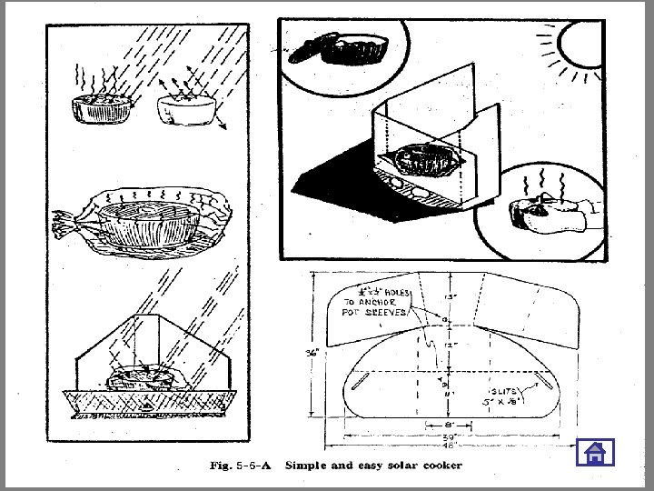
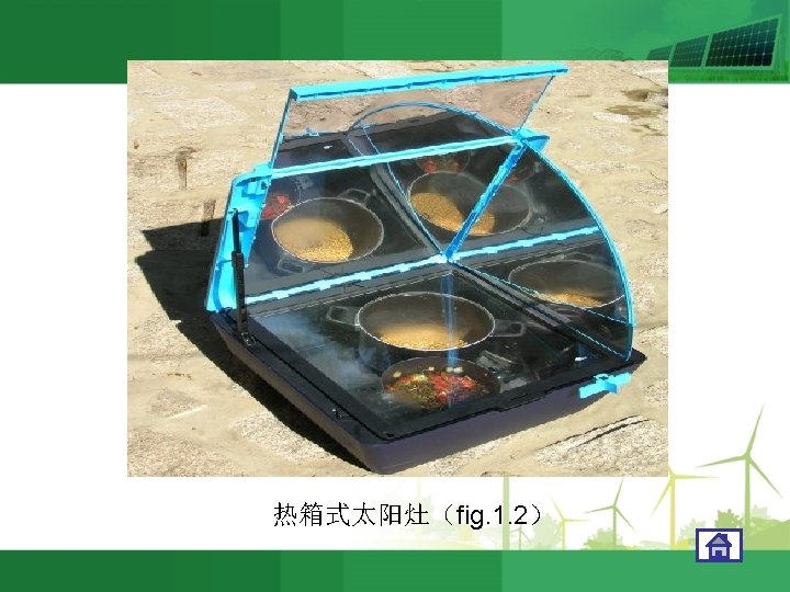
 Oven-type solar cooker (see Fig 5 -1,")
• Types of solar cooker 1) Oven-type solar cooker (see Fig 5 -1, Fig 5 -2 ) Fig. 5 -1 Oven type Fig. 5 -2 Oven type

SOLAR COOKER APPLICATIONS

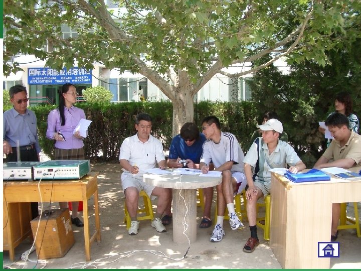
Women in Training Workshop of Solar cooker
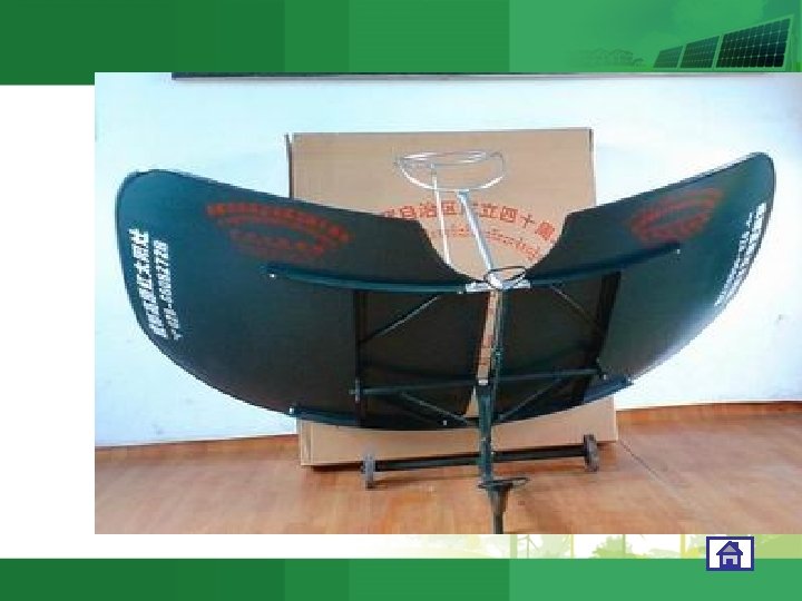
 Focusing-type solar cooker Principle: focusing by a paraboloid Focus temperature: 500 ℃/more Fig.")
2) Focusing-type solar cooker Principle: focusing by a paraboloid Focus temperature: 500 ℃/more Fig. 5 -3 Focusing type

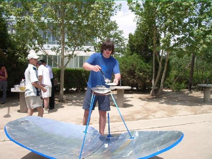
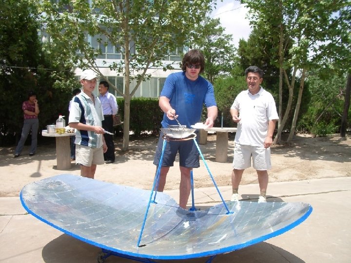
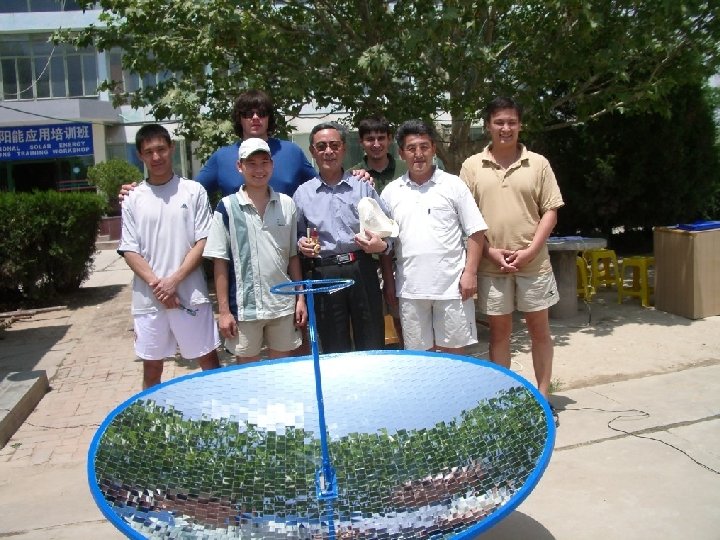
Various kinds of focusing-type cookers (see Fig 5 -3, Fig 5 -4, Fig 5 -5) Focusing type will be the main topic. Fig. 5 -5 Focusing type solar cooker

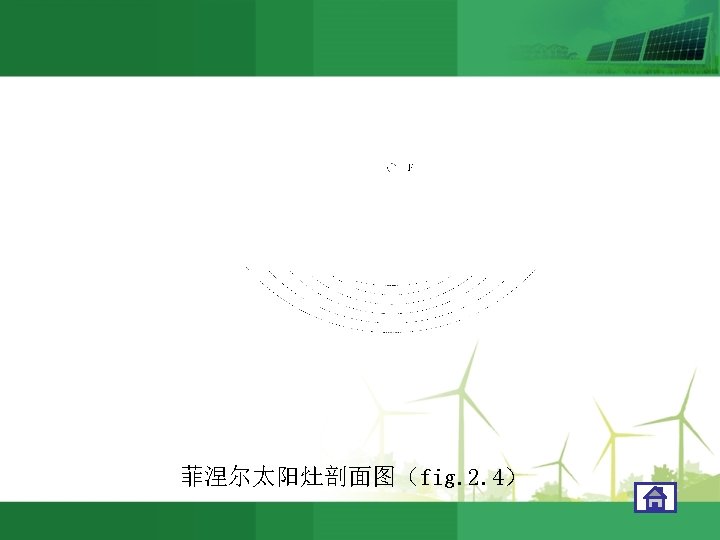
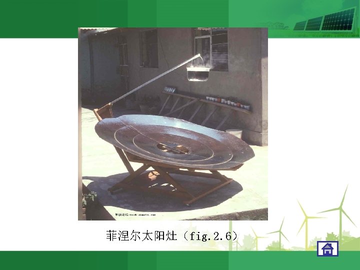
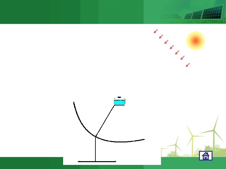
2. Basic principle of focusing type solar cooker • Principle: concentrating beam radiation by means of reflection/refraction with a focusing mirror onto the bottom of cooking vessel so that larger power and higher temperature will be achieved, approaching the cooking expectance. • Different kinds of focusing cooker: Parabolic solar cooker (See Fig 5 -6)
 Spherical mirror (See Fig. 5 -8) Fig.")
Cylindrical parabolic mirror (See Fig. 5 -7) Spherical mirror (See Fig. 5 -8) Fig. 5 -6 Parabolic type Fig. 5 -8 Spherical mirror Fig. 5 -7 Cylindrical Fig. 5 -9 Cone mirror
 Fresnel mirror (See Fig. 5 -10, Fig. 5")
Cone mirror (See Fig. 5 -9) Fresnel mirror (See Fig. 5 -10, Fig. 5 -11) For common focusing solar cooker, paraboloid mirror is applied. Fig. 5 -10 Fresnel mirror Fig. 5 -11 Fresnel mirror

SOLAR COOKER 5. THE DEVELOPMENT OF SOLAR COOKER IN CHINA

5 THE DEVELOPMENT OF SOLAR COOKER IN CHINA • The aim of research and development of solar cooker in China is to serve rural area in order to mitigate the contradiction of lacking fuel in countryside.

5. 1 The history of the development of solar cooker in China • In 1956, practice solar cooker was tested in China. • From 1973, solar cookers began to be experimented all over China. • In 1975, Anyang oven-type solar cooker was exhibited. • From 1979, solar cooker was developed rapidly in China. • In 1983, some key problems about solar cooker were resolved. • Currently, there approximate 480 thousands solar cookers in China. Gansu and Tibet are the best regions for solar cooker in China.

5. 2 The experiences for spreading solar cooker in China • ⑴ Supported by the government; • ⑵ Serving the rural area; • ⑶ Organizing technological volunteers for the development of solar cooker; • ⑷ Cooperating to overcome the technological key problems; • ⑸ Solar cooker industry; • ⑹ Solar cooker should be spread in the areas where are lack of fuel and rich in solar energy.

SOLAR COOKER 6. THE ECONOMICAL AND SOCIAL BENEFIT OF SOLAR COOKER

6. 1 THE ECONOMICAL AND SOCIAL BENEFIT • ⑴ Saving faggot / firewood for about 1000 kg/per year, equivalent to 200 RMB Yuan. (The price of a solar cooker is about 300 RMB) • ⑵ Replace a child’s work of collecting firewood every day, so that the school learning rate of rural children can be raised. • ⑶ Farmers can use the straw saved feeding domestic animals to increase fertilization, reducing village women’s burden. • ⑷ Ecological benefit.

SOLAR COOKER 4. BASIC STRUCTURE OF SOLAR COOKER

A solar cooker is consisted of three main parts: • Concentrator • Pot trestle • Supporter

4. 1 Concentrator • Function: Concentrator is for receiving solar radiation and reflecting and concentrating to the focal spot. • It is consisted of shell and mirror.
 FRP(fiber reinforced plastic)(纤维复合材料) Metal")
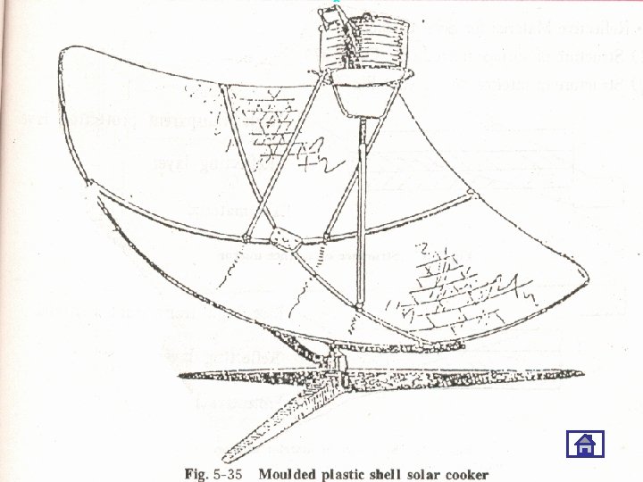
4. 1. 1 Materials of shell • • • Concrete(水泥) FRP(fiber reinforced plastic)(纤维复合材料) Metal sheet(金属板) Cast iron(铸铁) Glass(玻璃) Moulded plastic shell(模压塑料外壳) ABS plastic(ABS塑料) Card board(卡板) Mixture of concrete and paper pulp(混凝土 复合物和纸浆)

4. 1. 2 Materials of mirror • Glass mirror • Vacuum plated aluminum foil with polyester protecting film (This is now more commonly used as a material )

4. 2 Pot trestle • Function: Supporting the pot at a fixed optimum position • Keep horizontal or incline slightly • A pot trestle consists of : pot ring(锅圈) support rod (支撑杆) horizontal adjusting mechanism for the pot ring (水平调节机构)

• • 4. 2. 1 Common types of pot trestle ⑴ U-shaped pot trestle (Fig. 5 -18) ⑵ Double ring pot trestle (Fig. 5 -19) ⑶ Parallelogram- shaped pot trestle (Fig. 5 -20) ⑷ Stationary pot trestle (Fig. 5 -21)

U-shaped pot trestle

Double ring pot trestle

PARALLELOGRAM SHAPED POT TRESTLE 平行四边形支架

PARALLELOGRAM SHAPED POT TRESTLE 平行四边形支架

Stationary pot trestle

4. 3 Supporter of solar cooker • Function : Supporter is to support the concentrator, adjusting its movement to track the sun. • There are many methods to track the sun. The main methods are automatic and manual. The course will discuss the manual ones. • The tracking process means to track the azimuth and altitude of the sun.

ALTITUDE TRACKING: ORBIT 高度跟踪轨迹

AZIMUTH TRACKING SUPPORTER --WHEEL 轮式方位角 跟踪支架

Parabola On the earth, the track of an object, which is thrown out horizontally or in inclination, is parabola. • Geometric definition: the track of the dots which have equivalent distances with a fixed spot (focal point F) and a fixed straight line (standard line L) is parabola. (See fig. 5 -12)

Suppose M is an arbitrarily dot on parabola LP, constantly we have: MF = MD Equation: x 2 = 4 fy or x 2 = 2 Py Where: P — |FQ|, the distance from the spot F to the standard line LP; f — |OF| = P, the focal length of the parabola; F — focal point of parabola; O — vertex of the parabola. The straight line through focal point and vertex is the main optical axis of parabola.

2. 2 Paraboloid • If parabola LP is rotated round its main optical axis (symmetric axis) for a circumference, then a rotatory paraboloid SP will be formed. • Equation of paraboloid: x 2+y 2 -4 f = 0 • (See Fig. 5 -13) Fig. 5 -13 Paraboloid

2. 2 Paraboloid

Focusing-type solar cooker

Focusing principle

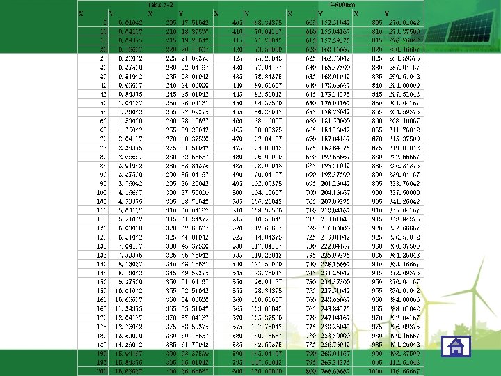
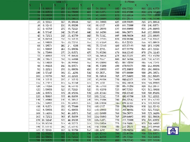
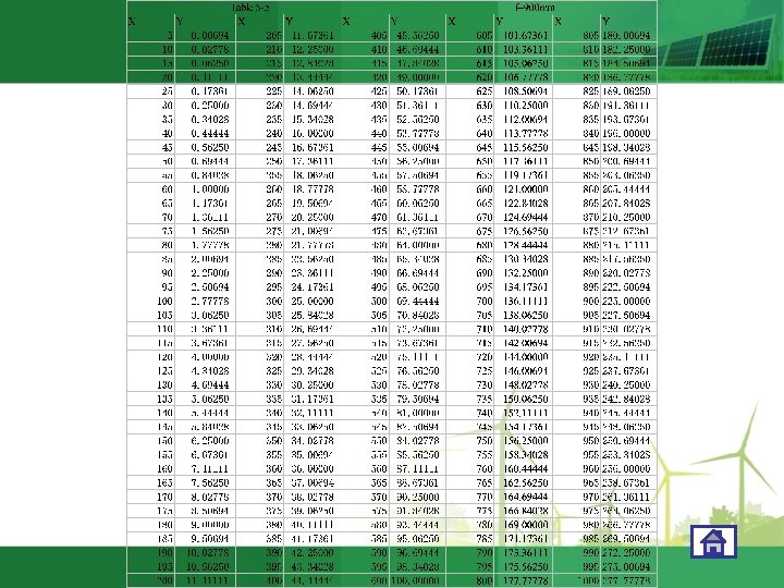
3. Method of drawing a parabola 2 • According to the formula x = 4 fy , we can get a series (x, y) when the f value is decided. • Mark out the dots relevant to each (x, y) at a rectangular coordinate system. (See Fig. 5 -14) Fig. 5 -14 Parabola
 for different focal length:")
• Reference of relative (x, y) for different focal length:


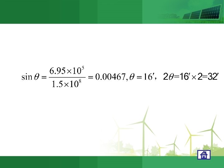
Theory of the sun image • Sun’s rays are basically parallel rays. In fact, the sun’s incident rays on the earth are not truly parallel; there is a small angle which is decided by the large diameter of the sun and the distance from the sun to the earth. This doesn’t affect the use of solar cookers.

1. 27 x 104 km 1. 39 x 106 km 1. 5 x 10⁸ km

concentration ratio • solar cooker’s concentration ratio is indicated by the reflection surface condenser role in the formation of focal spot on the main focus of the optical axis, the focal spot energy density may reach

2θ F D C δ A B
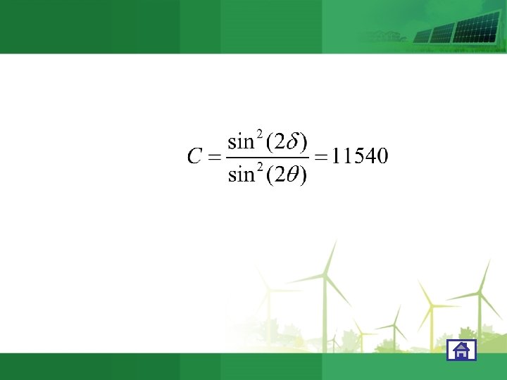

C——the actual concentration ratio ; β——β=2θ+4γ; γ——mirror the actual and the ideal angle error 。 For example : δ=45°, γ=1°
")
SOLAR COOKER 7. DESIGN PRINCIPLE OF SOLAR COOKER (FOCUSING-TYPE)

Solar cooker stove surface design • the solar cooker Reflector concentrating area is the main, Solar cooker stove surface is to determine the performance of key components, the selection and determine reflecting surface is very important, these parameters include: ① aperture area ; ② Focus distance ; ③ focal plane diameter; Now we will explain the determination of these parameters.

aperture area • when the main axis parallel with the solar ray , the stove surface in the direction perpendicular to the sun on the projection area. Obviously, the power aperture area is a decisive factor affecting solar cooker. aperture area can be calculated in accordance with the following formula:

——aperture area ——Rated degree of direct solar radiation ——Average optical efficiency of the solar cooker ——The power you need ,set up 900 W

focal distance • In the parabolic equation X ² = 4 fz and rotating parabolic equation x ² + y ² = 4 fz in, f is the focal length, it is determined, parabolic and parabolic also determined. In the design of solar cookers need to select the appropriate f value. There are several corresponding relationship:

• ① When the focal length is small, the pot rack to the lower, conducive to easy operation, but the stove surface is bound to do less, and thus less power also. • ② When the focal length is too large, clear projection angle increases, and help to improve efficiency, but a high pot rack location, the inconvenience of operation, stability decreased.

• To facilitate the operation, the general focal length range of options in the 7080 cm(centimetre ), the maximum operating altitude of not more than 125 cm(centimetre ).

Different aperture area of focus distance 面积/m² f/m 功率/w 1. 5 0. 6 650 2. 0 0. 75 1000 1. 8 0. 7 850 2. 2 0. 8 1100 1. 9 0. 75 900 2. 2 -2. 6 0. 85 11001250

focal plane diameter • the aperture area to determine , the size of the diameter of the focal plane decide focal plane temperature. The smaller the focal plane, focal plane temperature is higher, the greater the diameter of the focal plane, focal plane temperature is lower. For the solar cooker, the focal plane diameter if too small, although the focal plane temperature is high, but can cause local temperature is too high, the poor heat transfer, thermal efficiency but may decrease. Thus, the general focal plane temperature of not more than 1000 ℃ appropriate. • In general, the focal plane to 8 -10 cm in diameter is appropriate, must not exceed 15 cm.

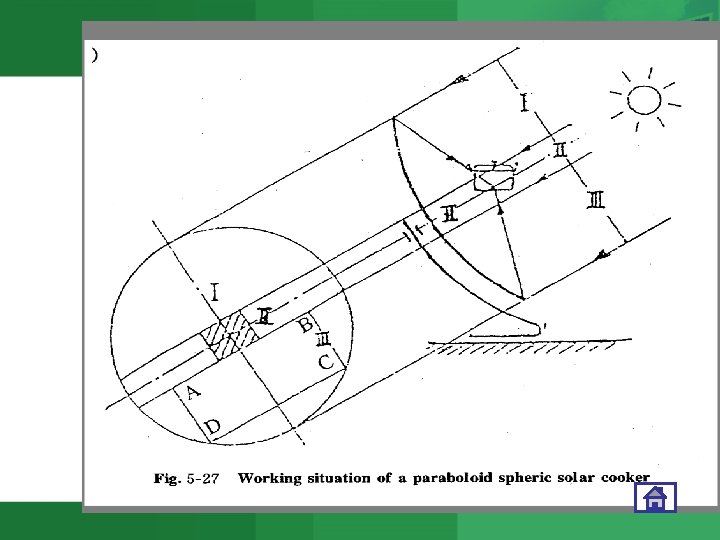
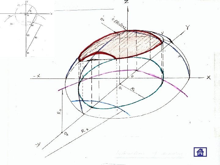
Deviated paraboloid concentrator • Working situations of a rotatory paraboloid /spherical solar cooker (Fig. 5 -27 (A), (B), (C) & (D)).

FOCAL SPOT POSITION AT NOON

FOCAL SPOT POSITION AT SUNRAISE & SUNSET

FOCAL SPOT POSITION AT NOON

FOCAL SPOT POSITION AT SUNRAISE & SUNSET

Central-partial parabolic solar cooker

Semi-partial parabolic solar cooker

Full partial parabolic solar cooker

DEVIATED PARABOLOID CONCENTRATOR

Collection cone principle • The process of using solar cookers, pot is always level, and therefore the surface of the stove and the bottom plane of the reflected light is always with the height of the sun's angle changes. The light shines on the bottom of the pot wall cf the light in the pot can be better absorbed, therefore, we must not be removed in the course of the light reflected to the reflective surface on the bottom part. We can build a solar cooker to collect reflected light cone, use it to determine the cut-smooth contours.
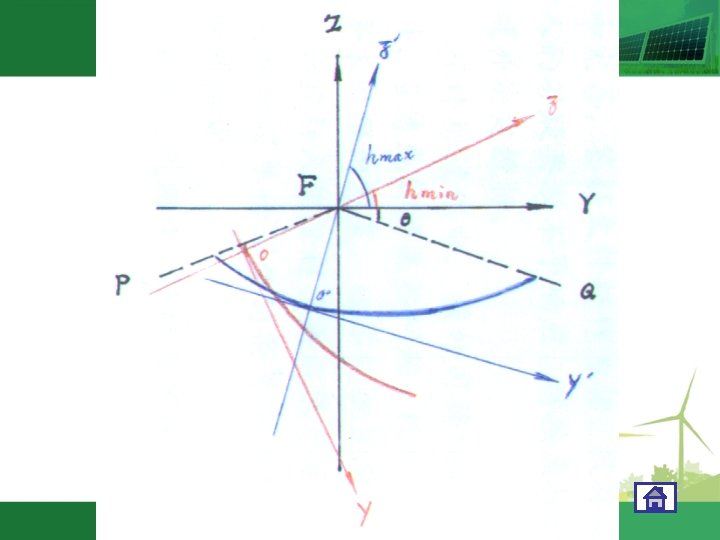
 Set the focal point F • (2) Triple-arc")
7. 3 TRIPLE-ARC DRAWING • (1) Set the focal point F • (2) Triple-arc of the sunlight receivine section. • So That the center of basic circle will be changed from O to O 1.
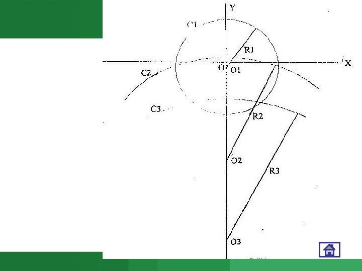

The center & radius of basic circle • Formula of the center of basic circle: (7 -1) • Formula of the radius of the basic circle • (7 -2)

The center of basic circle Where: O 1: The center of the basic circle; f: Focal length; hmax: Maximum altitude angle of the sun; : The rim angle (>20 º).

The radius of basic circle Where: R 1: The radius of the basic circle; f: Focal length; hmax: Maximum altitude angle of the sun; : The rim angle (>20 º).

The center of secondary circle Where: O 2: The center of the secondary circle; f: Focal length; hmin: Minimum altitude angle of the sun; : The rim angle(>20 º).

The radius of secondary circle Where: R 2: The radius of the secondary circle; f: Focal length; hmin: Minimum altitude angle of the sun; : The rim angle (>20 º).

The center & radius of third circle Where: O 3: The center of the 3 rd circle; R 3: The radius of the 3 rd circle; f: Focal length; hmin: Minimum altitude angle of the sun; : The rim angle; H: Operating height.

Examples: • • • 1. For f = 0. 8 m, hmin = 30°, when θ= 20°, hmax= 75°, H = 1. 08 m, then: O 1 = 0. 3166 m, O 2 = 1. 6456 m, O 3 = 2. 7713 m R 1 = 1. 1495 m, R 2 = 1. 7856 m, R 3 = 1. 8242 m

Examples: • 2. For f = 0. 7 m, hmin = 25°, when θ= 20°, hmax= 80°, H = 1. 08 m, then: • • O 1 = 0. 1830 m, O 2 = 1. 6600 m, O 3 = 3. 0020 m R 1 = 0. 9915 m, R 2= 1. 7200 m, R 3 = 1. 9540 m
")
SOLAR COOKER 8. DESIGN PRINCIPLE OF SOLAR COOKER (BASIC PARAMETERS)
 Definition • (2) Calculation of")
8. 1 DETERMINATION OF SOLAR COLLECTION AREA • (1) Definition • (2) Calculation of aperture area A= = A: aperture area , m 2; N: Effective power needed, W; I: Beam radiation on the plane perpendicular to sun ray, cal/cm 2 ·min; : Average optical efficiency of the solar cooker.

8. 2 SELECTION OF FOCAL LENGTH • Considering about angle between the reflected from the edge of concentrator and pot bottom plane . Generally should be not less than 15º, usually is about 20º.

8. 2 SELECTION OF FOCAL LENGTH • Consideration about operation • For easy operating, less focal length is required • Generally is about 70 - 80 cm

SOLAR COOKER 9. MATERIALS FOR SOLAR COOKER

9. 1 The materials for the shell of concentrator • 9. 1. 1 The basic principles for choosing the shell materials are following: • (1) Keeping the focal curved surface not to change shape and/crack; • (2) Rich in resource; • (3) Ease for producing; • (4) Convenient for transportation; • (5) Reasonable cost.
 Concrete")
9. 1. 2 Materials for the shell of concentrator • • • (1) Concrete shell (2) FRP(fiber reinforced plastic) shell (3) cast iron (4) Moulded plastic shell (5) Glass shell (6) Others: , Metal sheet shell ABS plastic, card board, mixture of concrete and paper pulp
 Structure of surface mirror •")
9. 2 REFLECTIVE MATERIALS FOR SOLAR COOKER • (1) Structure of surface mirror • (2) Structure of interior mirror

9. 2 REFLECTIVE MATERIALS FOR SOLAR COOKER • Structure of plastic film mirror

SOLAR COOKER 10. MANUFACTURING TECHNIQUES OF SOLAR COOKER
 Drawing the parabola")
10. 1 The main procedures of making focusing mirror • (1) Drawing the parabola
 Making a scraper")
10. 1 The main procedures of making focusing mirror • (2) Making a scraper with given curve of the parabola. • (3) Making a model with the scraper. • (4) making the shell of concentrator with the model.

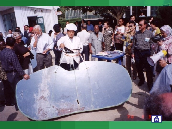
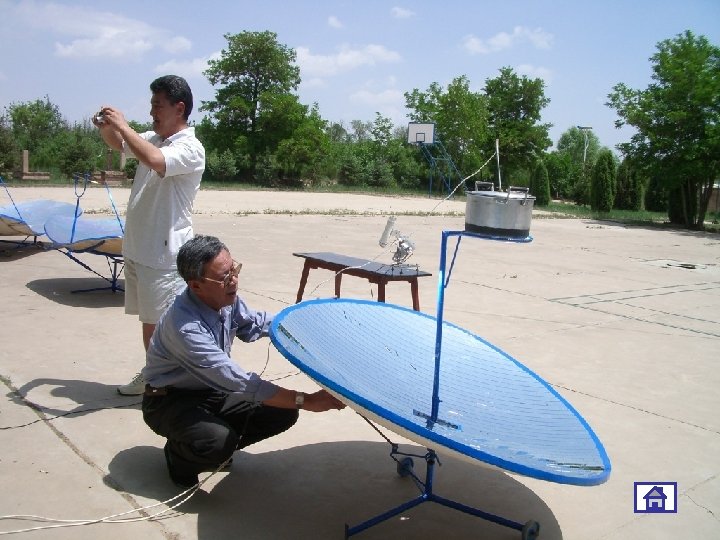
MAKING SOLAR COOKER

Make a solar cooker

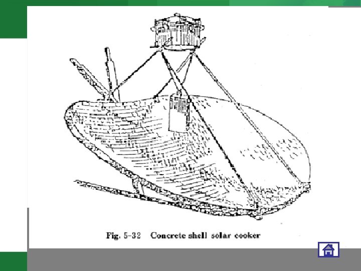
10. 2 The key point of making a glass concentrator with heat bending technique • ⑴ Keeping the model precision and smooth; • ⑵ Holding the heating and annealing curves during heat bending process (Fig. 5 -42). • (3) The scheme of the techniques (Fig. 543)

10. 3 The adhesion of mirrors and shell • ⑴ The small pieces of mirrors must be adhered smoothly; • ⑵ The gaps between the small pieces of mirrors must be tiny and full with adhesive; • ⑶ The gaps must be prevented from moisture and water. • In China, for concrete shell solar cooker, asphalt is usually used as adhesive; for polyester reflector, adhesive is usually attached and convenient to use.

Proportion of materials • • Mg. O: 20 kg; Sand: 10 kg; Sawdust: 4 kg; Water: Mg. Cl 2=1: 1. 2; Total weight: 15 kg; So: Water 6. 8 kg &Mg. Cl 2 8. 2 kg; Fiber glass mesh: 2 layers; The total dried weight: About 30 kg.

SOLAR COOKER

SOLAR COOKER

SOLAR COOKER

SOLAR COOKER

SOLAR COOKER 11. TECHNICAL REQUIREMENTS OF SOLAR COOKER

11. TECHNICAL REQUIREMENTS • China drafted the first national standard about solar cooker in the world. • The basic content of the standard: 1) Solar cooker’s manufacture should follow the technical documents. 2) The efficiency of water’s boiling:
 Focal zone’s area with over 400 ℃: 50 cm 2~ 200 cm 2")
3) Focal zone’s area with over 400 ℃: 50 cm 2~ 200 cm 2 4)The maximum operating height: ≤ 1. 25 m 5) The maximum operating distance: ≤ 0. 8 m 6) The minimum use altitude angle : ≤ 25° 7) The maximum use altitude angle : ≥ 70° 8) The tilt angle of the pot ring: ≤ 5° 9)Reflectivity of reflective material: Aluminum plate foil: ≥ 0. 8 others: ≥ 0. 7 The material should be durable and antiaging.
 The surface of concentrator should be smooth, without crackle and damage. The reflective")
10) The surface of concentrator should be smooth, without crackle and damage. The reflective material should be adhered well. 11) The painting on the pot should be smooth, even, endurable and uniform in tone. 12) The adjust mechanism should be easy and stable to operate.

Recommended collecting areas and focal length of solar cooker in the national standard are listed below : Table 6 Recommended collection area Table 7 Recommended focal length

SOLAR COOKER 12. THERMAL PERFORMANCE MEASUREMENT ABOUT FOCUSING SOLAR COOKER

12. Thermal measurement • The thermal performance is an important parameter of the solar cooker. We can evaluate different kinds of solar cooker according to its thermal performance. • At present there is no international standard or method for thermal measurement of solar cooker. Here is a brief introduction about the standard in China. • The thermal performance include: efficiency and focal temperature

12. 1 Optical efficiency • 12. 1. 1 Principle and method Definition of efficiency: The optical efficiency (η ) is the percentage value between the heat amount received by the liquid in the pot (Q u ) and the insolated beam solar radiation in the reflective surface (Q). Formula of efficiency:

Where: η — Optical efficiency of water heating; m — Mass of water, kg; t 2 — Final temperature of water, ℃; C — Heat capacity of water , k. J/kg. ℃; t 1 — Initial temperature of water, ℃; H — Accumulative amount of direct solar radiation per unit area, k. J/m 2; Ac — Aperture area, m 2. Carry out the measurement twice and take the mean value.

When the different pots are used in the same measurement, the mass and heat capacity of the pots should be taken in account of. Where: m 1 — mass of pot, kg; C 1 — heat capacity of pot, k. J/kg. Power of cooker: When the solar radiation is the same, the specified (rating) power

P=700 ·η· Ac 700 stands for the radiation value The actual effective power can be calculated by the following formula: Ps=60·m ·C· (t 2 -t 1)/860 ·T Where: Ps — Actual effective power of solar cooker; T — Measuring period, min; m — Mass of water, kg; C — Capacity of water, cal/g ·℃. Therefore, η is a comprehensive result of the optical efficiency and pot.
 The amount of water used")
• 12. 1. 2 Requirements for measurement (1) The amount of water used depends on the solar collection area. Its value should be twice as much as that of the solar cooker. (2) The initial temperature of water is 10 ℃ lower than ambient temperature; the final temperature is 10℃ higher than ambient temperature. (3) Beam solar radiation should be larger than 500 W/ m 2 , varying range: 100 W/ m 2.
 The range of solar altitude angle must be within 35°~65°. (5) Diameter of")
(4) The range of solar altitude angle must be within 35°~65°. (5) Diameter of pot: 24 cm. (6) Set thermometer in the center of the pot.

12. 1. 3 The conditions and instruments for measurement Conditions: * There is no reflective beam from any objects other than sun. * There is no shadow of other objects on the solar cooker. * Wind velocity: ≤ 2 m/s * Ambient temperature swing ≤ 30 ℃
 Direct radiation instrument 2) Thermometer 3) Anemometer 4)Stop watch 5) Bench scale")
Instruments: 1) Direct radiation instrument 2) Thermometer 3) Anemometer 4)Stop watch 5) Bench scale Fig. 5 -44 Situation of thermometer

Example: • • • Aperture area: 1. 8 m 2 Weight of water: 1. 8× 2 =3. 6 kg Ambient T = 24 ℃ Initial temperature of water t 1 = (24 -10)=14 ℃ Final t 2= (24+10) = 34 ℃ Accumulated beam solar radiation: 245. 3 k. J/m 2 Average intensity: 562. 6 W/m 2 Measure time: 7’ 16” (7. 27 min. ) η= 3. 6 × 4. 19 ×(34 -14)/245. 3 × 1. 8 = 68. 3%
 No Item Symbol Unit")
Work Sheet for Water Heating Efficiency Measurement (see p 118) No Item Symbol Unit Readings 1 2 1 Weight of Water m kg 3. 6 2 Average Ambient Temperature Ta ℃ 24 25 3 Initial Temperature of Water t 1 ℃ 14 15 4 Final Temperature of Water t 2 ℃ 34 35 5 Accumulative Beam Solar Radiation H k. J/㎡ 245. 3 250. 52 6 Aperture Area of Solar Cooker Ac ㎡ 1. 8 7 Average Beam Solar Radiation Ib W/㎡ 562. 36 848. 64 8 Measure Time T Min. 7. 27 4. 92 m/s < 2 % 68. 32 66. 90 9 10 Average Wind Speed Efficiency υ η

Example: calculation for measurement *Average Beam Solar Radiation Ib: Ib-1= 245300 J/7. 27× 60 s = 562. 36 W Ib-2= 250520 J/4. 92× 60 s = 848. 64 W *Average efficiency: η= (68. 32%+66. 90%)/2 = 67. 61% *Specified power: P = 700× 67. 61%×Ac = 851. 9 W *Effective power Ps: Ps= 60·m ·C· (t 2 -t 1)/860 ·T = 60× 3. 6× 1×(34 -14)/7. 27(4. 92) × 860 = 691(1021)W

12. 2 Measurement of temperature of focal zone • • Temperature: 600~800℃ Area: 50~200 c㎡ Shape: Circle or ellipse with smooth edge. Tmax≤ 1000℃
 Thermocouple/thermograph ranging")
12. 2. 1 Measuring instruments for the focal zone temperature • (1) Thermocouple/thermograph ranging temperature 1300~1600℃; • (2) Temperature displaying painted plate to show the temperature by color changing; • (3) Tempil.

12. 2. 2 The methods of measuring the shape, area and temperature of focal zone • (1) Adjust and focus the solar cooker to the optimum position; • (2) Put the temperature displaying plate on the pot ring of the solar cooker with the side coated with temperature displaying paint upward for three minutes, then take the plate away, observe the shape and size of focal zone; • (3)Copy the shape of the focal zone from the plate with a transparency and estimate the area.

12. 2. 2 The methods of measuring the shape, area and temperature of focal zone

SOLAR COOKER • 13. THE OPERATION AND MAINTENANCE OF SOLAR COOKER
 Assemble a solar cooker carefully following the specification booklet")
Operation & Maintenance • (1) Assemble a solar cooker carefully following the specification booklet ; • (2) First adjust the azimuth, then altitude; • (3) Adjust and track the sun every 15 minutes; • (4) Don’t try to operate your solar cooker when there is no sunshine; • (5) Safety problems; • (6) Take care your solar cooker, especially the mirrors.
 Interval work; • 2)Outdoor operation; •")
14. 1 Disadvantages of solar cooker • 1) Interval work; • 2)Outdoor operation; • 3) Common solar cooker can not track the sun automatically.
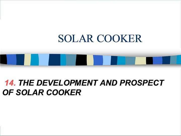
 Outdoor concentrator of the solar")
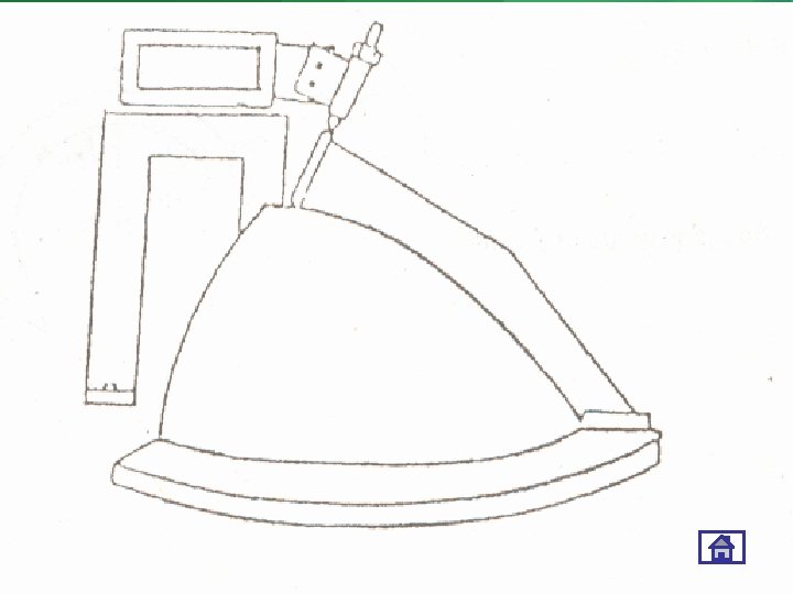
14. 2 Advantages of indoor solar cooker • (1) Outdoor concentrator of the solar cooker can track the sun automatically, and can transfer the heat energy gained into indoor room; • (2) The heat energy transferred into room can be used directly or be stored. • *Indoor solar cooker (Fig. 5 -52)
- Slides: 150