
MAE 5130 VISCOUS FLOWS Introduction to Boundary Layers
MAE 5130: VISCOUS FLOWS Introduction to Boundary Layers October 26, 2010 Mechanical and Aerospace Engineering Department Florida Institute of Technology D. R. Kirk 1
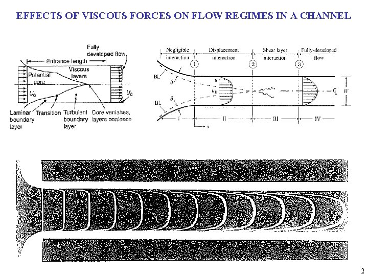
EFFECTS OF VISCOUS FORCES ON FLOW REGIMES IN A CHANNEL 2
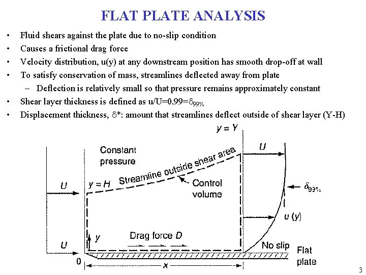
FLAT PLATE ANALYSIS • • • Fluid shears against the plate due to no-slip condition Causes a frictional drag force Velocity distribution, u(y) at any downstream position has smooth drop-off at wall To satisfy conservation of mass, streamlines deflected away from plate – Deflection is relatively small so that pressure remains approximately constant Shear layer thickness is defined as u/U=0. 99=d 99% Displacement thickness, d*: amount that streamlines deflect outside of shear layer (Y-H) 3
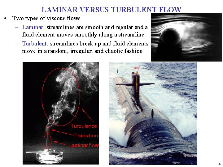
LAMINAR VERSUS TURBULENT FLOW • Two types of viscous flows – Laminar: streamlines are smooth and regular and a fluid element moves smoothly along a streamline – Turbulent: streamlines break up and fluid elements move in a random, irregular, and chaotic fashion 4
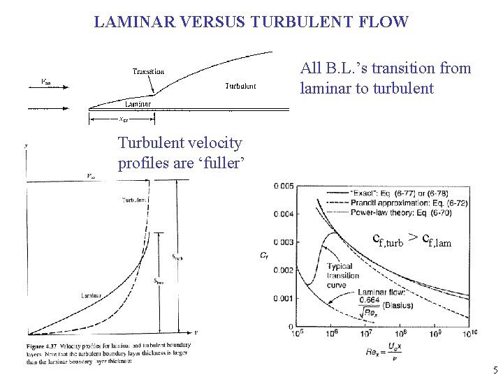
LAMINAR VERSUS TURBULENT FLOW All B. L. ’s transition from laminar to turbulent Turbulent velocity profiles are ‘fuller’ cf, turb > cf, lam 5

LAMINAR TO TURBULENT TRANSITION 1. Stable laminar flow near leading edge 2. Unstable 2 D Tollmien-Schlichting waves 3. Development of 3 D unstable waves and ‘hairpin’ eddies 4. Vortex breakdown at regions of high localized shear 5. Cascading vortex breakdown into fully 3 D fluctuations 6. Formation of turbulent spots at locally intense fluctuations 7. Coalescence of spots into fully turbulent flow • Smoke-flow visualization of flow with transition induced by acoustic input – Re. L = 814, 000 – f = 500 Hz 6

EXAMPLE OF FLOW SEPARATION • Velocity profiles in a boundary layer subjected to a pressure rise – (a) start of pressure rise – (b) after a small pressure rise – (c) after separation • Flow separation from a surface – (a) smooth body – (b) salient edge 7
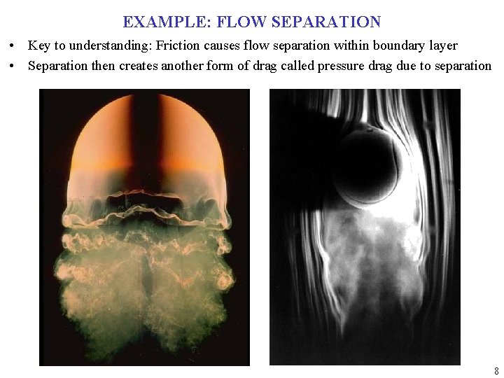
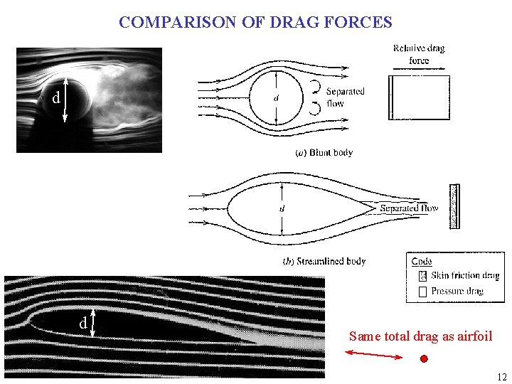
EXAMPLE: FLOW SEPARATION • Key to understanding: Friction causes flow separation within boundary layer • Separation then creates another form of drag called pressure drag due to separation 8
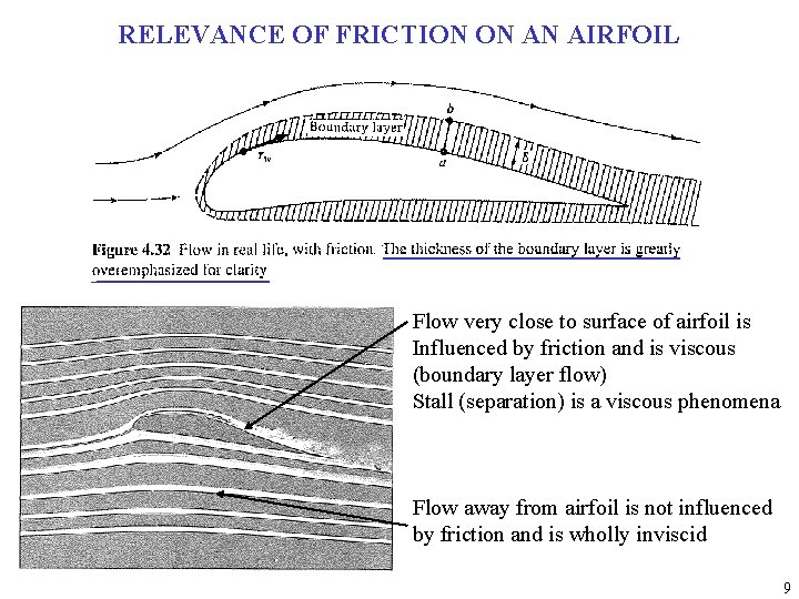
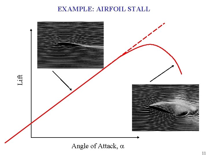
RELEVANCE OF FRICTION ON AN AIRFOIL Flow very close to surface of airfoil is Influenced by friction and is viscous (boundary layer flow) Stall (separation) is a viscous phenomena Flow away from airfoil is not influenced by friction and is wholly inviscid 9
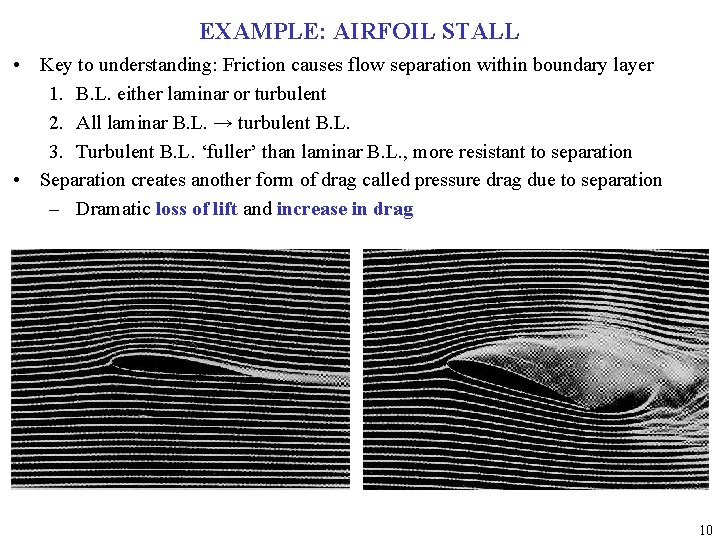
EXAMPLE: AIRFOIL STALL • Key to understanding: Friction causes flow separation within boundary layer 1. B. L. either laminar or turbulent 2. All laminar B. L. → turbulent B. L. 3. Turbulent B. L. ‘fuller’ than laminar B. L. , more resistant to separation • Separation creates another form of drag called pressure drag due to separation – Dramatic loss of lift and increase in drag 10
Lift EXAMPLE: AIRFOIL STALL Angle of Attack, a 11
COMPARISON OF DRAG FORCES d d Same total drag as airfoil 12

INCOMPRESSIBLE VS. COMPRESSIBLE DEFINITIONS Incompressible Compressible 13
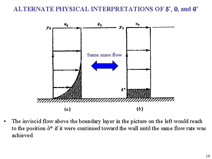
ALTERNATE PHYSICAL INTERPRETATIONS OF d*, q, and q* Same mass flow • The inviscid flow above the boundary layer in the picture on the left would reach to the position d* if it were continued toward the wall until the same flow rate was achieved 14
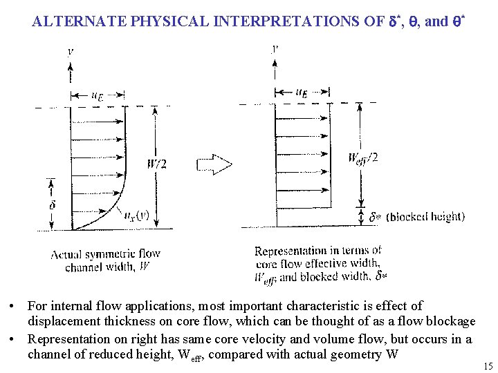
ALTERNATE PHYSICAL INTERPRETATIONS OF d*, q, and q* • For internal flow applications, most important characteristic is effect of displacement thickness on core flow, which can be thought of as a flow blockage • Representation on right has same core velocity and volume flow, but occurs in a channel of reduced height, Weff, compared with actual geometry W 15
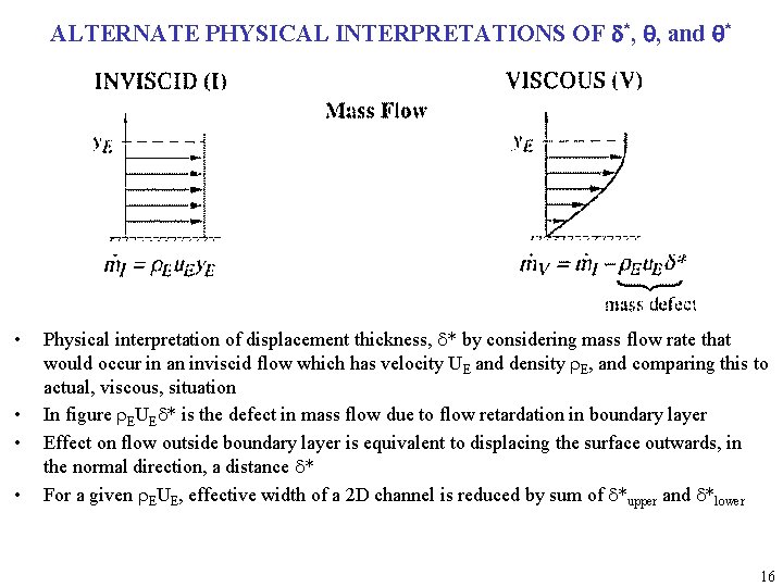
ALTERNATE PHYSICAL INTERPRETATIONS OF d*, q, and q* • • Physical interpretation of displacement thickness, d* by considering mass flow rate that would occur in an inviscid flow which has velocity UE and density r. E, and comparing this to actual, viscous, situation In figure r. EUEd* is the defect in mass flow due to flow retardation in boundary layer Effect on flow outside boundary layer is equivalent to displacing the surface outwards, in the normal direction, a distance d* For a given r. EUE, effective width of a 2 D channel is reduced by sum of d*upper and d*lower 16
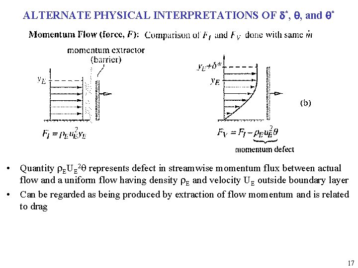
ALTERNATE PHYSICAL INTERPRETATIONS OF d*, q, and q* • Quantity r. EUE 2 q represents defect in streamwise momentum flux between actual flow and a uniform flow having density r. E and velocity UE outside boundary layer • Can be regarded as being produced by extraction of flow momentum and is related to drag 17
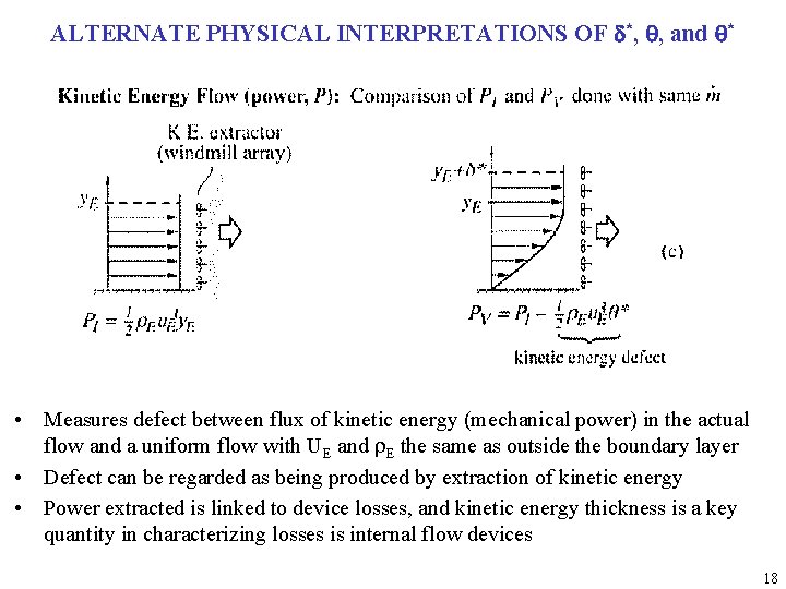
ALTERNATE PHYSICAL INTERPRETATIONS OF d*, q, and q* • Measures defect between flux of kinetic energy (mechanical power) in the actual flow and a uniform flow with UE and r. E the same as outside the boundary layer • Defect can be regarded as being produced by extraction of kinetic energy • Power extracted is linked to device losses, and kinetic energy thickness is a key quantity in characterizing losses is internal flow devices 18
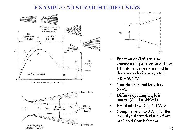
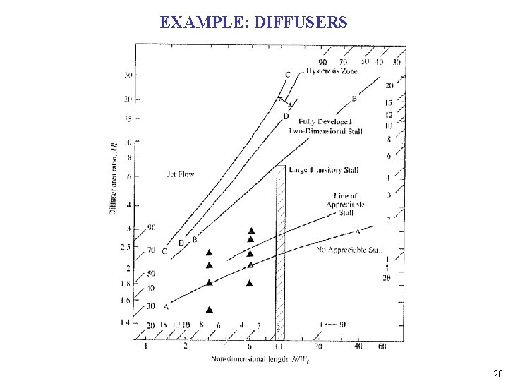
EXAMPLE: 2 D STRAIGHT DIFFUSERS • • • Function of diffuser is to change a major fraction of flow KE into static pressure and to decrease velocity magnitude AR = W 2/W 1 Non-dimensional length is N/W 1 Diffuser opening angle is tan(q)=(AR-1)(2 N/W 1) For ideal flow, Cp, i=1 -1/AR 2 Compare prior to AA and after AA, significant deviation from predicted flow behavior 19
EXAMPLE: DIFFUSERS 20
- Slides: 20