MADE BY NADAR SAPNA S SR NO 1

MADE BY: - NADAR SAPNA S. . SR NO. 1

WHY STUDY DRAFTING? Drafting is a form of graphic communication Ø “A picture is worth a thousand words. ” Ø

DRAFTING AS A LANGUAGE Ø Drafting is called a “universal language” Symbols (lines and figures) have specific meaning are used Ø The symbols accurately describe the shape, size, material, finish, and fabrication or assembly of a product Ø

DRAFTING AS A LANGUAGE Drafting is also the “language of industry” Ø Industry uses this precise language because the drawings must communicate the information the designer had in mind to those who produce the product. Ø

FIELDS OF DRAFTING Aerospace Ø Architectural Ø Automotive Ø Electrical Ø Electronic Ø Printed circuitry design Ø Topographical Ø ETC… Ø v Yes! IT IS EVERYWHERE!!

DRAWING BOARD § § In order to prevent warping , the drawing board is made of narrow strips glued edge to edge with well seasoned pine or soft wood. Surface of the board should be free from cracks and it should be absolutely flat.
The blade 2)The stock Paper")
T- Square Mostly T-Square is made of two parts. 1)The blade 2)The stock Paper Set-Up Ø Horizontal Lines Base for triangles to draw vertical lines. Ø Ø

MINI DRAFTER Ø Ø Ø Mini drafter is used in many drawing and design offices to do work faster. It serves the purpose of T-Square , Set. Square , Protractor and Scales. Two blades of the drafter are accurately set to right angles to each other.

DRAFTING EQUIPMENT Ø Compass Ø Ø Protractor Ø Ø Draw circles and arcs Measure and layout angles Templates Ø Drawing repetitive features

TRIANGLES Tool for drawing vertical & inclined lines Ø 45° Triangle Ø Ø 30°-60° Triangle
 Ø Mechanical drafter Ø Metric Ø Architecture")
TYPES OF SCALES Ø Engineer (Civil) Ø Mechanical drafter Ø Metric Ø Architecture

FRENCH CURVE Also called an Irregular curve Ø Consists of a variety of curves that can be used when arcs are not satisfactory Ø

PENCILS Ø Mechanical Ø Lead Holders Ø Wooden

LEADS 5 B 6 B 4 B 2 B 3 B SOFT Very soft leads, smudge easily. Used for art work of various kinds and full-size details in architectural drawing. 9 H 8 H 7 H 6 H 5 H B HB F H 2 H 3 H MEDIUM 4 H HARD Used where extreme accuracy is required. Softer grades (right) used for line work on engineering drawings. Draw very light lines. General purpose work. Softer grades (right) used for technical sketching, lettering, freehand work. Harder grades (left) used for line work on machine & architectural drawings.

DRAFTING EQUIPMENT Ø Erasers Ø Brush Ø Ø Clean drawings w/out smudging Erasing Shield Ø Erase near lines that should not be erased

DIVIDER Looks like a compass, but both legs have steel pints at the end Ø Tool used for measurement purposes Ø
 line in sketching. Ø First,")
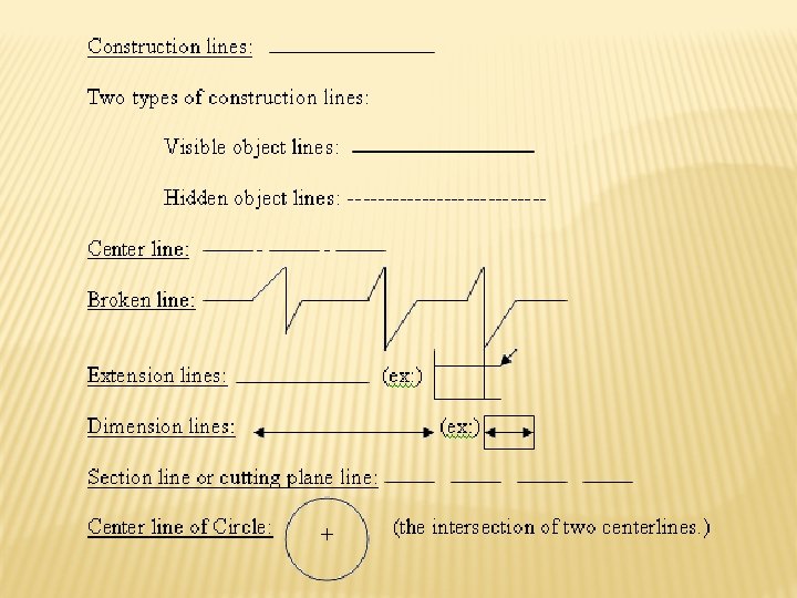
BORDER LINE The border line is the heaviest (thickest) line in sketching. Ø First, draw light construction lines as a guide. Ø Then, go over them using a pencil with a heavy rounded point to provide the border lines. Ø

CENTER LINE Centerlines are made up of alternate long (3/4 in. to 1 ½ in. ) and short (1/8 in. ) dashes with 1/16 in. spaces between. Ø These are drawn about the same weight as dimension and extension lines, and are used to locate centers of symmetrical objects. Ø

CUTTING PLANE LINE A cutting-plane line indicates where an object has been cut to show interior features. Ø Two types are used: Ø Ø¼ in. dashes with 1/16 in. spacing Ø A long dash (3/4 in. to 1 ½ in. ), then two short dashes (1/8 in. ) with 1/16 in. spacing. Ø Draw the cutting-plane line slightly heavier than an object line, using a pencil with a rounded point.

CLASSIFICATION OF ENGG. CURVES 1. CONICS 2. CYCLOIDAL CURVES 3. INVOLUTE 4. SPIRAL 5. HELIX

What is Cone ? It is a surface generated by moving a Straight line keeping one of its end fixed & other end makes a closed curve. The fixed point is known as vertex or apex. Vertex/Apex The closed curve is known as base. If the base/closed curve is a circle, we get a cone. If the base/closed curve is a polygon, we get a pyramid. 90º Base

The line joins apex to the center of base is called axis. If axes is perpendicular to base, it is called as right circular cone. Vertex/Apex If axis of cone is not perpendicular to base, it is called as oblique cone. Cone Axis Generator The line joins vertex/ apex to the circumference of a cone is known as generator. 90º Base

CONICS Definition : - The locus of point moves in a plane such a way that the ratio of its distance from fixed point (focus) to a fixed Straight line (Directrix) is always constant. Directrix M C Conic Curve P V F Focus Fixed straight line is called as directrix. Fixed point is called as focus.

The line passing through focus & perpendicular to directrix is called as axis. The intersection of conic curve with axis is called as vertex. Directrix M C Vertex Conic Curve P V F Focus Axis

Directrix M C Vertex N Conic Curve P V F Focus Q Distance of a point from focus Distance of a point from directrix Ratio = = Eccentricity = PF/PM = QF/QN = VF/VC = e Axis

ELLIPSE Ellipse is the locus of a point which moves in a plane so that the ratio of its distance from a fixed point (focus) and a fixed straight line (Directrix) is a constant and less than one. M Directrix Vertex C N Ellipse P V Q Axis F Focus Eccentricity=PF/PM = QF/QN < 1.

ELLIPSE – DIRECTRIX FOCUS METHOD D 1 e R =6 f` P 6 P 7 P P 5 P 3 4 < 45º Eccentricity = 2/3 V 1 F 1 QV 1 2 = = R 1 V 1 3 1 2 3 4 5 6 7 V 1 F 1 Dist. Between directrix 90° & focus = 50 mm P 1’ Tangen P ’ t 1 part = 50/(2+3)=10 2 P 3’P ’ 4 P 5’ P ’ mm 6 7 V 1 F 1 = 2 part = 20 mm S T V R = 3 part = 30 mm 1 1 N T P 1 P 2 d Normal R 1 Q a b c 1 a R= Directrix D 1 Ellipse f g

ARC OF CIRCLE’S METHOD P 4 P 3 C P 4 P 3 P 2 P 1 1 A = R Rad = B 1 F 1 A `R=A 2 1 Ta P 1’ ng en F 2 O 2 3 4 2 B = R P 1’ No rm al t P 2’ 90° P 2’ P 3’ B P 4’ D P 4’ P 3’

T Q 11 N P 11 11 P 12 12 1 P 1 A F 1 2 10 Major Axis 2 P 3 3 P 9 9 4 DP 4 P 7 F 2 B 7 6 5 P 6 P 5 e = AF 1/AQ CF 1=CF 2=1/2 AB 3 4 8 P 8 8 O 1 P 2` 9 CP 10 Axis 12 10 Minor CONCENTRIC CIRCLE METHOD 5 6 7

4 Ta ng en t A F 4’ P 3’ Minor Axis P 2 2 S P 1 1 R =A B/ 2 No rm 3 al 0 P P 4 C P 4’ P 3 ØØ E Directrix OBLONG METHOD P 2’ 3’ 2’ P 1’ 1’ Major Axis 1 F 1 2 3 4 4’ 3’ 2’ F 2 1’ P 1 0’ B P 1’’ P 2’’ P 3 P 4’’ D P 3’’

ELLIPSE IN PARALLELOGRAM 1 0 H P 2 60° 0 O 1 2 3 xis J M Q 1 Q 2 0 or A S 4 ajor P 1 Min 2 P 3 4 4 5 P AP 6 5 is 1 6 5 4 3 Ax 2 C P 4 G S 2 R 3 S 1 D R 1 I R 2 Q 3 Q 4 3 Q 5 4 Q 6 B 5 5 6 R 4 S 3 K 0 1 2

Uses Of Ellipse : - Shape of a man-hole. Shape of tank in a tanker. Flanges of pipes, glands and stuffing boxes. Shape used in bridges and arches. Monuments. Path of earth around the sun. Shape of trays etc.

- Slides: 34