LTE LTESmall Cell LTE Mobile Access Adaptive Modulation

課程單元目標 • • • 了解 LTE 通道品質與訊號雜訊比 了解 LTE-Small Cell 調變技術的基礎 了解 LTE Mobile Access 了解 Adaptive Modulation and Coding 技術 了解 Resource Blocks 與 Channels 架構 2
 • CQI stands for Channel Quality Indicator. • It")
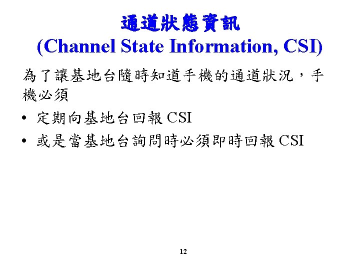
LTE Channel Quality Indicator (CQI) • CQI stands for Channel Quality Indicator. • It is an indicator carrying the information on how good/bad the communication channel quality is. • CQI is used in both LTE and HSDPA. 4

Channel Quality Indicator • CQI is the information that UE sends to the network. • Practically, CQI implies the following two – Current Communication Channel Quality – UE wants to get the data with a transport block size, which in turn can be directly converted into throughput. 5
 –")
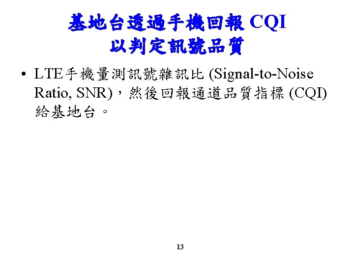
How UE Estimates the CQI • Major factors involved: – signal-to-noise ratio (SNR) – signal-to-interference plus noise ratio (SINR) – signal-to-noise plus distortion ratio (SNDR) • The SNR/SINR/SNDR can be derived from the mobile channel models. • Correlation between SNR measures and Block Error Rate (BLER) 6

CQI Value and Expected PDSCH Modulation Scheme • In LTE, there are 15 different CQI values ranging from 1 to 15 (4 bits) and mapping between CQI and modulation scheme • The transport block size is defined in the 3 GPP TS 36. 213. • The CQI indices and their interpretations are given for reporting CQI based on QPSK, 16 QAM, 64 QAM and 256 QAM. 7
 8 3 GPP TS")
4 -bit CQI Table (QPSK, 16 QAM and 64 QAM) 8 3 GPP TS 36. 213, Table 7. 2. 3 -1
 9 3")
4 -bit CQI Table (QPSK, 16 QAM, 64 QAM and 256 QAM) 9 3 GPP TS 36. 213, Table 7. 2. 3 -2
 10 3 GPP TS 36. 213,")
4 -bit CQI Table (QPSK and 16 QAM) 10 3 GPP TS 36. 213, Table 7. 2. 3 -3
")
4 -bit CQI Table (3 GPP TS 36. 213, Table 7. 2. 3 -2) • In Network (e. Node. B) programming, the number of resource blocks and MCS for each CQI value can be used to properly allocate the resources for each of UEs. – With the modulation scheme in the tables, we would get a certain range of MCS to use for each CQI index. – Code Rate is also needed to get the proper MCS and Number of RBs. – In the tables, a set of single/determined value for MCS and Number of RBs that meet the modulation scheme and Code Rate requirement can be determined. 11
 • Depending which value")
What would happen if UE send an inaccurate CQI? (1/3) • Depending which value UE reports, the network transmits data with different transport block size. – If network gets high CQI value from UE, it transmit the data with larger transport block size and vice versa. 16
 • What if the")
What would happen if UE send an inaccurate CQI? (2/3) • What if the network sends a large transport block even though UE reports low CQI? Ø It is highly probable that UE failed to decode it (cause CRC error on the UE side) and UE send NACK to network and the network have to retransmit it which in turn cause waste of radio resources. 17
 • What if UE")
What would happen if UE send an inaccurate CQI? (3/3) • What if UE report high CQI even when the real channel quality is poor? Ø In this case, the network would send a large transport block size according to the CQI value and it would become highly probable that UE failed to decode it (cause CRC error on UE side), and UE send NACK to network and the network have to retransmit it which in turn cause waste of radio resources. 18

CQI vs. SNR • The main criteria for UE to determined CQI value is SNR. • The exact mapping between the measured SNR and CQI may vary depending on each modem manufacturer, but overall correlation between CQI and SNR would be similar. • Every modem manufacturer would keep their own mapping table in their physical layer protocol stack but in most case the venders would not open those tables in public. 19
 • 111 Tx Mode 0 re-tx: – TM 1,")
CQI vs. SNR: Example (1/3) • 111 Tx Mode 0 re-tx: – TM 1, Number of Tx Antenna = 1, Number of Rx Antenna = 1, HARQ Max retransmission = 0 • 111 Tx Mode 3 re-tx: – TM 1, Number of Tx Antenna = 1, Number of Rx Antenna = 1, HARQ Max retransmission = 3 • 222 Tx Mode: – TM 2, Number of Tx Antenna = 2, Number of Rx Antenna = 2 • 322 Tx Mode: – TM 3, Number of Tx Antenna = 2, Number of Rx Antenna = 2 • 342 Tx Mode: – TM 3, Number of Tx Antenna = 4, Number of Rx Antenna = 2 20
 21")
CQI vs. SNR: Example (2/3) 21
 22")
CQI vs. SNR: Example (3/3) 22

 for")
Radio Technologies • Long Term Evolution • Orthogonal Frequency Division Multiple Access (OFDMA) for the downlink • Single Carrier Frequency Division Multiple Access (SC-FDMA) for the uplink. 24

What is OFDM 25

OFDM Signal Generation Chain • OFDM signal generation is based on Inverse Fast Fourier Transform (IFFT) operation on transmitter side: • On receiver side, an FFT operation will be used. 26

Difference between OFDM and OFDMA 27

OFDMA Time-Frequency Multiplexing 28

LTE – Spectrum Flexibility 29

SC-FDMA Signal Generation Chain • DFT “pre-coding” is performed on modulated data symbols • Sub-carrier mapping allows flexible allocation of signal to available sub-carriers • IDFT and cyclic prefix (CP) insertion as in OFDM. • Each subcarrier carries a portion of superposed DFT spread data symbols, therefore SC-FDMA is also referred to as DFT-spread -OFDM (DFT-s-OFDM). 30
 vs. SC-FDMA (UL) (1/2) • OFDMA: each sub-carrier only carries information related")
OFDMA (DL) vs. SC-FDMA (UL) (1/2) • OFDMA: each sub-carrier only carries information related to one specific symbol • SC-FDMA: each sub-carrier contains information of ALL transmitted symbols 31
 vs. SC-FDMA (UL) (2/2) 32")
OFDMA (DL) vs. SC-FDMA (UL) (2/2) 32

LTE Mobile Access 33

Mobile Access 34
 LTE provides all of the following functions using a flat all-IP")
LTE Services (1/2) LTE provides all of the following functions using a flat all-IP core that interconnects multiple access technologies and provides user experience regardless of the access method. • fixed telephone networks • cable TV networks • cellular telephone networks • data networks. 35
 LTE provides • quality of service (Qo. S) support • a")
LTE Services (2/2) LTE provides • quality of service (Qo. S) support • a wide variety of applications and services • mobility and routing management and • LTE ensures that the core sees the mobile networks simply as another IP network. • Mobile handover between access types will be seamless. 36
 • LTE is the first technology designed explicitly for the")
Next Generation Network (1/3) • LTE is the first technology designed explicitly for the Next Generation Network (NGN). • LTE is set to become the de-facto NGN mobile access network standard. • LTE takes advantage of the NGN's capabilities to provide an always-on mobile data experience comparable to wired networks. 37
 LTE Release 8 supports peak data rates of up to")
Next Generation Network (2/3) LTE Release 8 supports peak data rates of up to • 300 Mbps on the downlink 75 Mbps on the uplink when using a 20 MHz channel bandwidth and 4 x 4 MIMO. • A more common configuration of 20 MHz and 2 x 2 MIMO supports peak rates of 150 Mbps on the downlink and 50 Mbps on the uplink. • LTE Advanced (Release 10) supports peak data rates of up to 1200 Mbps on the downlink and 600 Mbps on the uplink using both Carrier Aggregation (CA) and higher-order MIMO. 38
 • LTE has flexible duplex methods – both Frequency Division")
Next Generation Network (3/3) • LTE has flexible duplex methods – both Frequency Division Duplex (FDD) and Time Division Duplex (TDD) are valid spectrum allocations – allows LTE technology to fit within either existing or new carrier spectrum allocations • LTE supports scalable RF channel bandwidths – Allowed values are 1. 4, 3, 5, 10, 15, and 20 MHz • LTE Advanced supports CA with up to five 20 MHz carriers for a total of 100 MHz operating bandwidth. 39

OFDMA • LTE takes advantage of OFDMA • OFDMA is a multi-carrier scheme that allocates radio resources to multiple users. • OFDMA uses Orthogonal Frequency Division Multiplexing (OFDM). • For LTE, OFDM splits the carrier frequency bandwidth into many small subcarriers spaced at 15 k. Hz. 40

OFDMA: Modulation and Bandwidth • LTE modulates each individual subcarrier using the QPSK, 16 -QAM, or 64 -QAM digital modulation formats. • OFDMA assigns each user the bandwidth needed for their transmission. • Unassigned subcarriers are off, thus reducing power consumption and interference. 41

OFDM vs. OFDMA Each color represents a burst of user data. In a given period, OFDMA allows users to share the available bandwidth. 42

OFDMA: Modulation and Bandwidth • OFDMA uses OFDM; however, it is the scheduling and assignment of resources that makes OFDMA distinctive. • OFDM: the entire bandwidth belongs to a single user for a period • OFDMA: multiple users are sharing the bandwidth at each point in time 43

SC-FDMA • In the uplink, LTE uses a pre-coded version of OFDM called Single Carrier Frequency Domain Multiple Access (SC-FDMA). • SC-FDMA is used in place of OFDMA due to – High current requirements for OFDMA-based power amplifiers and correspondingly short battery life – Lower Peak-to-Average Power Ratio for SC-FDMAbased power amplifiers results in extended battery life along with improved uplink performance 44

SC-FDMA vs. OFDMA • SCFDMA: data spreads across multiple subcarriers • OFDMA: each subcarrier transports unique data. • The need for a complex receiver makes SC- FDMA unacceptable for the downlink due to size and processing power limitations in a wireless device. 45
 46")
Adaptive Modulation/Coding (AMC) 46
 – the ability of the network")
Adaptive Modulation/Coding • Adaptive Modulation and Coding (AMC) – the ability of the network to determine the modulation type and the coding rate dynamically – based on the current RF channel conditions reported by the UE in Measurement Reports • RF channel conditions are determined by – Call Quality Indicator (CQI) measurement reports from the wireless device – Re-transmission attempts from the HARQ (Hybrid Automatic Repeat Request) acknowledgement/retransmission 47

AMC and Spatial Multiplexing • In addition to AMC, the MIMO mode can be dynamically set to Transmit Diversity or one of several Spatial Multiplex modes. – based on additional channel conditions reported by the LTE device using the Rank Indicator (RI). • Digital modulation for information transport – QPSK – 16 -QAM – 64 -QAM 48
 The ideal constellations for each modulation: Each dot represents a possible")
Adaptive Modulation (1/3) The ideal constellations for each modulation: Each dot represents a possible symbol 49
 50")
Adaptive Modulation (2/3) 50
 • • • Ø QPSK: four symbol states and each symbol")
Adaptive Modulation (3/3) • • • Ø QPSK: four symbol states and each symbol carries two bits of information 16 -QAM: 16 symbol states and each symbol carries 4 bits 64 -QAM: 64 symbol states and each symbol carries 6 bits Higher-order modulation is more sensitive to poor channel conditions than the lower-order modulation: Ø because the detector in the receiver must resolve smaller differences as the constellations become more dense Ø Smaller amplitude and phase differences as the constellation becomes more dense. Ø The network would set the modulation to a lower order if poor channel conditions are reported by the wireless device. 51

Adaptive Modulation and Coding • Coding: an error correction methodology – adds extra bits to the data stream that allow error correction. – Specified as fractions, Code Rates specify the number of data bits in the numerator and the total number of bits in the denominator. – Example: • If the Code Rate is 1/3, protection bits are added so one bit of data is sent as three bits. – If errors are reported by the wireless device, the network would increase the error correction to compensate. 52
 • Most modern wireless communication techniques use MIMO –")
Multiple Input Multiple Output (MIMO) • Most modern wireless communication techniques use MIMO – to increase the data rate to a user – to provide better coverage at the cell edge • Various techniques are available – spatial multiplexing: transmission of separate data streams from each antenna – transmit diversity: transmission of identical streams of data from each antenna – receive diversity: reception on multiple antennas 53
 Single Input Multiple Output (SIMO)")
Generalized MIMO • • Single Input Single Output (SISO) Single Input Multiple Output (SIMO) Multiple Input Single Output (MISO) Multiple Input Multiple Output (MIMO) 54
 55")
Generalized MIMO (cont’d) 55

Downlink MIMO • For LTE Rel. 8 – downlink MIMO configurations from SISO to 2 x 2 and 4 x 4 MIMO are supported. – The MIMO configuration changes dynamically based on measurement reports from the wireless device. • For LTE Advanced – MIMO configurations up to 8 x 8 in the downlink and 4 x 4 in the uplink are supported in combination with Carrier Aggregation (CA), which uses multiple carriers. 56

Downlink MIMO For LTE Rel. 8 • When a user is close to a base station and propagation conditions are optimal, 2 x 2 MIMO may be used with a high data rate to the wireless device. • When a user is at a cell edge, one or both of the diversity modes may be used to increase the Signal to Interference plus Noise Ratio (SINR). 57

Resource Blocks 與 Channels 架構 58

Frame Structures • In LTE, downlink and uplink transmissions are organized into frames that are 10 milliseconds (ms) long. • A frame is divided into 10 subframes that are 1 ms each. • A subframe is divided into 2 slots that are 0. 5 ms each. • Each slot contains 7 symbols, where Ts (Sample Time) is the amount of time dedicated to each OFDM sample, and is the basic unit of time for LTE. • Ts = 1/(15000 x 2048) seconds or about 32. 6 nanoseconds. 59
 Timing and symbol allocations for FDD with normal cyclic prefix (CP)")
Frame Structures (FDD) Timing and symbol allocations for FDD with normal cyclic prefix (CP) 60
 TDD frames contain two half frames, where at least one of")
Frame Structures (TDD) TDD frames contain two half frames, where at least one of the half frames contains a special subframe carrying three fields of switch information including Downlink Pilot Time Slot (Dw. PTS), Guard Period (GP) and Uplink Pilot Time Slot (Up. PTS). 61

Frame Structure and Bandwidth Concepts • 10 one-ms subframes comprise a 10 -ms frame • Two 0. 5 -ms slots comprise a one-ms subframe • 7 symbols comprise a 0. 5 -ms slot Ø Taking into account both time and frequency aspects, the smallest modulation structure in LTE is one symbol in time vs. one Resource Element (RE). 62

Resource Elements and Resource Blocks • Resource Elements are aggregated into dimensions of 7 symbols by 12 subcarriers. • The number of symbols in a RB depends on the Cyclic Prefix (CP) in use. – When a normal CP is used, the RB contains seven symbols. – When an extended CP is used due to extreme delay spread or multimedia broadcast modes, the RB contains six symbols. 63

64

Resource Blocks • The number of RBs that can fit within a channel varies proportionally to the bandwidth of the channel. Logically, as the channel bandwidth increases, the number of RBs can increase. • The Transmission Bandwidth Configuration is the maximum number of Resource Blocks that can fit within the channel bandwidth with some guard band. • For a channel with the maximum channel bandwidth of 20 MHz (for LTE Rel. 8), 100 RBs can fit within this bandwidth. 65

66

67

Physical Channels and Signals • The LTE frame is defined in terms of physical channels and physical signals, which are positioned by the LTE standard at specific positions in the frame in terms of subcarriers and symbols, respectively. • Channels are defined as carrying information received from higher layers. • Signals are defined as originating at the physical layer. 68
 69")
Downlink Physical Channels (FDD) 69
 • Used to transport user data,")
Downlink Physical Channels Physical Downlink Shared Channel (PDSCH) • Used to transport user data, the PDSCH is designed for high data rates. • Modulation options include QPSK, 16 -QAM, and 64 QAM. • Spatial multiplexing is exclusive to the PDSCH. • The RBs associated with this channel are shared among users. 70
 Physical Broadcast Channel (PBCH) • The PBCH is used to")
Downlink Physical Channels (cont’d) Physical Broadcast Channel (PBCH) • The PBCH is used to send cell-specific system identification and access control parameters every 4 th frame (40 ms). • The PBCH uses QPSK modulation. 71
 Physical Control Format Indicator Channel (PCFICH) • The PCFICH is")
Downlink Physical Channels (cont’d) Physical Control Format Indicator Channel (PCFICH) • The PCFICH is used to inform the wireless device how many OFDM symbols will be used for the PDCCH in a subframe. • The PCFICH uses QPSK modulation. 72
 Physical Downlink Control Channel (PDCCH) • The PDCCH is used")
Downlink Physical Channels (cont’d) Physical Downlink Control Channel (PDCCH) • The PDCCH is used to transmit uplink and downlink resource scheduling allocations to the wireless devices. • The PDCCH maps onto resource elements in up to the first three OFDM symbols of the first slot of a subframe. • The PDCCH uses QPSK modulation. • The value of the PCFICH indicates the number of symbols used for the PDCCH. 73
 Physical Multicast Channel (PMCH) • The PMCH carries multimedia broadcast")
Downlink Physical Channels (cont’d) Physical Multicast Channel (PMCH) • The PMCH carries multimedia broadcast information. • The PMCH has multiple options for modulation including QPSK, 16 -QAM, or 64 -QAM. • Multicast information can be sent to multiple wireless devices simultaneously. 74
 Physical Hybrid ARQ Indicator Channel (PHICH) • PHICH carries ACK/NACKs")
Downlink Physical Channels (cont’d) Physical Hybrid ARQ Indicator Channel (PHICH) • PHICH carries ACK/NACKs in response to uplink transmissions in order to request retransmission or confirm the receipt of blocks of data. • ACKs and NACKs are part of the HARQ mechanism 75
 Reference Signal (RS) • Wireless devices use the RS for")
Downlink Physical Channels (cont’d) Reference Signal (RS) • Wireless devices use the RS for downlink channel estimation, allowing the wireless device to effectively demodulate the downlink signal. • RS’s are the product of a two-dimensional orthogonal sequence and a two-dimensional pseudo-random sequence. • Three different sequences are available: the orthogonal sequence and 170 possible sequences for the pseudorandom number (PRN), resulting in 510 possible RS sequences. • The RS uses the first and fifth symbols under normal Cyclic Prefix (CP) operation, and the first and fourth symbols for extended CP operation; the location of the RS on the subcarriers varies. 76
 Primary and Secondary Synchronization Signal (P-SS and S-SS) • Wireless")
Downlink Physical Channels (cont’d) Primary and Secondary Synchronization Signal (P-SS and S-SS) • Wireless devices use the Primary Synchronization Signal (P-SS) for timing and frequency acquisition during cell search. – The P-SS carries part of the cell ID and provides slot timing synchronization. It uses one of three Zadoff-Chu sequences. • Wireless devices use the Secondary Synchronization Signal (S-SS) in cell search. – It provides frame timing synchronization and the remainder of the cell ID. – The S-SS uses two 31 -bit binary sequences and BPSK modulation. 77
 • The PUCCH carries uplink control")
Uplink Physical Channels Physical Uplink Control Channel (PUCCH) • The PUCCH carries uplink control information and is never transmitted simultaneously with PUSCH data. • PUCCH conveys control information including Channel Quality Indication (CQI), ACK/NACK responses of the UE to the HARQ mechanism, and uplink scheduling requests. 78
 Physical Uplink Shared Channel (PUSCH) • Uplink user data is")
Uplink Physical Channels (cont’d) Physical Uplink Shared Channel (PUSCH) • Uplink user data is carried by the PUSCH. • Resources for the PUSCH are allocated on a subframe basis by the UL scheduler. • Subcarriers are allocated in units of RB’s, and may be hopped from sub-frame to sub-frame. • The PUSCH may employ QPSK, 16 -QAM, or 64 QAM modulation. 79
 Physical Random Access Channel (PRACH) • The PRACH carries the")
Uplink Physical Channels (cont’d) Physical Random Access Channel (PRACH) • The PRACH carries the random access preamble and coordinates and transports random requests for service from UE’s. • The PRACH channel transmits access requests (bursts) when a wireless device desires to access the LTE network (call origination or paging response). 80

Uplink Reference Signal • Two variants of the UL reference signal: – The demodulation reference signal facilitates coherent demodulation, and is transmitted in the fourth SC-FDMA symbol of the slot. – A sounding reference signal is used to facilitate frequency-dependent scheduling. • Both variants of the UL reference signal use Constant Amplitude Zero Autocorrelation (CAZAC) sequences. 81

LTE UE Categories 82

References 1. 2. 3 GPP TS 36. 213 LTE Quick Reference – 3. Mohammad T. Kawser, et al. , “Downlink SNR to CQI Mapping for Different Multiple Antenna Techniques in LTE, ” International Journal of Information and Electronics Engineering, Vol. 2, No. 5, 2012, pp. 757 -760. 吳建樺, “定期回報基地台通道狀態 LTE手機連線品質有保障, ” 新通訊 2012 年 11 月號 141 期《 技術前瞻 》。 Anritsu LTE_Reource_Guide 4. 5. – – 6. (2009) http: //web. cecs. pdx. edu/~fli/class/LTE_Reource_Guide. pdf (2015) http: //www. cs. columbia. edu/6181/hw/anritsu. pdf Anritsu Understanding LTE – 7. 8. 9. http: //www. sharetechnote. com/html/Handbook_LTE_CQI. html http: //www. sharetechnote. com/Docs/anritsu_understanding_lte 6. pdf 3 GPP TS 36. 211 3 GPP TS 36. 212 Chris Johnson, “Long term Evolution IN BULLETS, ” 2 nd Ed. , 2012. http: //www. lte-bullets. com/ 83
- Slides: 83