Low Vibration Cryogenics for LIGO Voyager Brett Shapiro
![Low Vibration Cryogenics for LIGO Voyager Brett Shapiro Stanford University G 1500246 -v 2 Low Vibration Cryogenics for LIGO Voyager Brett Shapiro Stanford University G 1500246 -v 2](https://slidetodoc.com/presentation_image/5ff75a1f3fea5ea2f9a85c3c9c8cb540/image-1.jpg)
Low Vibration Cryogenics for LIGO Voyager Brett Shapiro Stanford University G 1500246 -v 2 - Pasadena - 17 March 2015 1
![LIGO III Cryosystem ISI Stage 2 … 124 K Silicon test mass G 1500246 LIGO III Cryosystem ISI Stage 2 … 124 K Silicon test mass G 1500246](http://slidetodoc.com/presentation_image/5ff75a1f3fea5ea2f9a85c3c9c8cb540/image-2.jpg)
LIGO III Cryosystem ISI Stage 2 … 124 K Silicon test mass G 1500246 - Pasadena - 17 March 2015 2
![LIGO III Cryosystem ISI Stage 2 … Heat shield at 80 K 124 K LIGO III Cryosystem ISI Stage 2 … Heat shield at 80 K 124 K](http://slidetodoc.com/presentation_image/5ff75a1f3fea5ea2f9a85c3c9c8cb540/image-3.jpg)
LIGO III Cryosystem ISI Stage 2 … Heat shield at 80 K 124 K Silicon test mass G 1500246 - Pasadena - 17 March 2015 3
![LIGO III Cryosystem ISI Stage 2 … Room temperature Heat shield at 80 K LIGO III Cryosystem ISI Stage 2 … Room temperature Heat shield at 80 K](http://slidetodoc.com/presentation_image/5ff75a1f3fea5ea2f9a85c3c9c8cb540/image-4.jpg)
LIGO III Cryosystem ISI Stage 2 … Room temperature Heat shield at 80 K 124 K Silicon test mass G 1500246 - Pasadena - 17 March 2015 4
![LIGO III Cryosystem ISI Stage 2 … Room temperature Vacuum flange Cold link Heat LIGO III Cryosystem ISI Stage 2 … Room temperature Vacuum flange Cold link Heat](http://slidetodoc.com/presentation_image/5ff75a1f3fea5ea2f9a85c3c9c8cb540/image-5.jpg)
LIGO III Cryosystem ISI Stage 2 … Room temperature Vacuum flange Cold link Heat shield at 80 K 124 K Silicon test mass G 1500246 - Pasadena - 17 March 2015 5
![LIGO III Cryosystem ISI Stage 2 … Room temperature Vacuum flange Cold link Heat LIGO III Cryosystem ISI Stage 2 … Room temperature Vacuum flange Cold link Heat](http://slidetodoc.com/presentation_image/5ff75a1f3fea5ea2f9a85c3c9c8cb540/image-6.jpg)
LIGO III Cryosystem ISI Stage 2 … Room temperature Vacuum flange Cold link Heat shield at 80 K Beam tube shield at 80 K 10 m 124 K Silicon test mass G 1500246 - Pasadena - 17 March 2015 6
![LIGO III Cryosystem ISI Stage 2 … Room temperature Vacuum flange Cold link Heat LIGO III Cryosystem ISI Stage 2 … Room temperature Vacuum flange Cold link Heat](http://slidetodoc.com/presentation_image/5ff75a1f3fea5ea2f9a85c3c9c8cb540/image-7.jpg)
LIGO III Cryosystem ISI Stage 2 … Room temperature Vacuum flange Cold link Heat shield at 80 K Beam tube shield at 80 K Challenge – integrating cryo and seismic • Seismic shorts • cold link modes • Long heat path • Thermal drifts 10 m 124 K Silicon test mass G 1500246 - Pasadena - 17 March 2015 7
![LIGO III Cryosystem ISI Stage 2 … Room temperature Vacuum flange Cold link Heat LIGO III Cryosystem ISI Stage 2 … Room temperature Vacuum flange Cold link Heat](http://slidetodoc.com/presentation_image/5ff75a1f3fea5ea2f9a85c3c9c8cb540/image-8.jpg)
LIGO III Cryosystem ISI Stage 2 … Room temperature Vacuum flange Cold link Heat shield at 80 K Beam tube shield at 80 K Challenge – integrating cryo and seismic • Seismic shorts • cold link modes • Long heat path • Thermal drifts 10 m Challenge – balance 10 m shield from suspended platform 124 K Silicon test mass G 1500246 - Pasadena - 17 March 2015 8
![Actively controlled shield (ETM) Stage 2 Gate Valve St 0 Cryo pump St 0 Actively controlled shield (ETM) Stage 2 Gate Valve St 0 Cryo pump St 0](http://slidetodoc.com/presentation_image/5ff75a1f3fea5ea2f9a85c3c9c8cb540/image-9.jpg)
Actively controlled shield (ETM) Stage 2 Gate Valve St 0 Cryo pump St 0 z 124 K test mass 9
![Actively controlled shield (ETM) Stage 2 Gate Valve St 0 Cryo pump St 0 Actively controlled shield (ETM) Stage 2 Gate Valve St 0 Cryo pump St 0](http://slidetodoc.com/presentation_image/5ff75a1f3fea5ea2f9a85c3c9c8cb540/image-10.jpg)
Actively controlled shield (ETM) Stage 2 Gate Valve St 0 Cryo pump St 0 z 124 K test mass 80 K heat shield and lower structure
![Actively controlled shield (ETM) Blade springs Stage 2 Gate Valve St 0 Cryo pump Actively controlled shield (ETM) Blade springs Stage 2 Gate Valve St 0 Cryo pump](http://slidetodoc.com/presentation_image/5ff75a1f3fea5ea2f9a85c3c9c8cb540/image-11.jpg)
Actively controlled shield (ETM) Blade springs Stage 2 Gate Valve St 0 Cryo pump St 0 z 124 K test mass 80 K heat shield and lower structure
![Actively controlled shield (ETM) Blade springs Cold link Stage 2 Gate Valve St 0 Actively controlled shield (ETM) Blade springs Cold link Stage 2 Gate Valve St 0](http://slidetodoc.com/presentation_image/5ff75a1f3fea5ea2f9a85c3c9c8cb540/image-12.jpg)
Actively controlled shield (ETM) Blade springs Cold link Stage 2 Gate Valve St 0 Cryo pump St 0 z 124 K test mass 80 K heat shield and lower structure
![Actively controlled shield (ETM) Sensors between heat shield and stage 2 Blade springs Cold Actively controlled shield (ETM) Sensors between heat shield and stage 2 Blade springs Cold](http://slidetodoc.com/presentation_image/5ff75a1f3fea5ea2f9a85c3c9c8cb540/image-13.jpg)
Actively controlled shield (ETM) Sensors between heat shield and stage 2 Blade springs Cold link Stage 2 Gate Valve St 0 Cryo pump St 0 z 124 K test mass 80 K heat shield and lower structure
![Actively controlled shield (ETM) Sensors between heat shield and stage 2 Actuators between stage Actively controlled shield (ETM) Sensors between heat shield and stage 2 Actuators between stage](http://slidetodoc.com/presentation_image/5ff75a1f3fea5ea2f9a85c3c9c8cb540/image-14.jpg)
Actively controlled shield (ETM) Sensors between heat shield and stage 2 Actuators between stage 0 and heat shield Blade springs Cold link Stage 2 Gate Valve St 0 Cryo pump St 0 z 124 K test mass 80 K heat shield and lower structure
![Actively controlled shield (ETM) Sensors between heat shield and stage 2 Actuators between stage Actively controlled shield (ETM) Sensors between heat shield and stage 2 Actuators between stage](http://slidetodoc.com/presentation_image/5ff75a1f3fea5ea2f9a85c3c9c8cb540/image-15.jpg)
Actively controlled shield (ETM) Sensors between heat shield and stage 2 Actuators between stage 0 and heat shield ≈ 900 mm dia Gate Valve Blade springs 80 K baffled beam tube shield Cold link Stage 2 St 0 z 10 m Cryo pump 124 K test mass 80 K heat shield and lower structure
![Actively controlled shield (ETM) Sensors between heat shield and stage 2 Actuators between stage Actively controlled shield (ETM) Sensors between heat shield and stage 2 Actuators between stage](http://slidetodoc.com/presentation_image/5ff75a1f3fea5ea2f9a85c3c9c8cb540/image-16.jpg)
Actively controlled shield (ETM) Sensors between heat shield and stage 2 Actuators between stage 0 and heat shield ≈ 900 mm dia Gate Valve Blade springs 80 K baffled beam tube shield Cold link Stage 2 St 0 z 10 m Cryo pump ACB in suspended HS 124 K test mass 80 K heat shield and lower structure
![Actively controlled shield (ETM) Sensors between heat shield and stage 2 Actuators between stage Actively controlled shield (ETM) Sensors between heat shield and stage 2 Actuators between stage](http://slidetodoc.com/presentation_image/5ff75a1f3fea5ea2f9a85c3c9c8cb540/image-17.jpg)
Actively controlled shield (ETM) Sensors between heat shield and stage 2 Actuators between stage 0 and heat shield Room temp upper structure, disconnected from cold lower ≈ 900 mm dia Gate Valve Blade springs 80 K baffled beam tube shield Cold link Stage 2 St 0 z 10 m Cryo pump ACB in suspended HS 124 K test mass 80 K heat shield and lower structure
![Pros/cons of separate cryo and seismic • Pros – No seismic isolation impact – Pros/cons of separate cryo and seismic • Pros – No seismic isolation impact –](http://slidetodoc.com/presentation_image/5ff75a1f3fea5ea2f9a85c3c9c8cb540/image-18.jpg)
Pros/cons of separate cryo and seismic • Pros – No seismic isolation impact – Shorter heat transfer path – Much greater choice of heat transfer methods – Allows more science payload (bigger test masses) • Cons – Requires another active control system with many additional sensors and actuators per BSC G 1500246 - Pasadena - 17 March 2015 18
![To make 1 structure or 2? - in the case of a suspended heat To make 1 structure or 2? - in the case of a suspended heat](http://slidetodoc.com/presentation_image/5ff75a1f3fea5ea2f9a85c3c9c8cb540/image-19.jpg)
To make 1 structure or 2? - in the case of a suspended heat shield Temperature of cold part Thermal stress + alignment of warm part Vibrational mode frequencies Damping of vibrational modes Relative complexity of construction 1 structure 2 structures: warm & cold Note: • For 1 structure, the heat shield is not integrated. It cools the lower structure radiatively, along with the suspension. • For 2 structures, the heat shield is fully integrated into the lower structure as 1 unit. Good Fair Risky Show stopper 19
![To make 1 structure or 2? - in the case of a suspended heat To make 1 structure or 2? - in the case of a suspended heat](http://slidetodoc.com/presentation_image/5ff75a1f3fea5ea2f9a85c3c9c8cb540/image-20.jpg)
To make 1 structure or 2? - in the case of a suspended heat shield Temperature of cold part Thermal stress + alignment of warm part Vibrational mode frequencies Damping of vibrational modes Relative complexity of construction 1 structure ? 2 structures: warm & cold ? Note: • For 1 structure, the heat shield is not integrated. It cools the lower structure radiatively, along with the suspension. • For 2 structures, the heat shield is fully integrated into the lower structure as 1 unit. Good Fair Risky Show stopper 20
![Conceptual LIGO III Solid. Works Sketches G 1500246 - Pasadena - 17 March 2015 Conceptual LIGO III Solid. Works Sketches G 1500246 - Pasadena - 17 March 2015](http://slidetodoc.com/presentation_image/5ff75a1f3fea5ea2f9a85c3c9c8cb540/image-21.jpg)
Conceptual LIGO III Solid. Works Sketches G 1500246 - Pasadena - 17 March 2015 21
![a. LIGO LLO Y End Solid. Works Model 5 m 10 m G 1500246 a. LIGO LLO Y End Solid. Works Model 5 m 10 m G 1500246](http://slidetodoc.com/presentation_image/5ff75a1f3fea5ea2f9a85c3c9c8cb540/image-22.jpg)
a. LIGO LLO Y End Solid. Works Model 5 m 10 m G 1500246 - Pasadena - 17 March 2015 22
![LIGO III End Station Conceptual Model Gate valve G 1500246 - Pasadena - 17 LIGO III End Station Conceptual Model Gate valve G 1500246 - Pasadena - 17](http://slidetodoc.com/presentation_image/5ff75a1f3fea5ea2f9a85c3c9c8cb540/image-23.jpg)
LIGO III End Station Conceptual Model Gate valve G 1500246 - Pasadena - 17 March 2015 ISI 23
![LIGO III End Station Conceptual Model Gate valve ISI Stage 0 G 1500246 - LIGO III End Station Conceptual Model Gate valve ISI Stage 0 G 1500246 -](http://slidetodoc.com/presentation_image/5ff75a1f3fea5ea2f9a85c3c9c8cb540/image-24.jpg)
LIGO III End Station Conceptual Model Gate valve ISI Stage 0 G 1500246 - Pasadena - 17 March 2015 24
![LIGO III End Station Conceptual Model Gate valve ISI Stage 0 G 1500246 - LIGO III End Station Conceptual Model Gate valve ISI Stage 0 G 1500246 -](http://slidetodoc.com/presentation_image/5ff75a1f3fea5ea2f9a85c3c9c8cb540/image-25.jpg)
LIGO III End Station Conceptual Model Gate valve ISI Stage 0 G 1500246 - Pasadena - 17 March 2015 Suspended heat shield / lower quad structure 80 K 25
![LIGO III End Station Conceptual Model Gate valve ISI Stage 0 Transmitted beam shield LIGO III End Station Conceptual Model Gate valve ISI Stage 0 Transmitted beam shield](http://slidetodoc.com/presentation_image/5ff75a1f3fea5ea2f9a85c3c9c8cb540/image-26.jpg)
LIGO III End Station Conceptual Model Gate valve ISI Stage 0 Transmitted beam shield G 1500246 - Pasadena - 17 March 2015 Suspended heat shield / lower quad structure 80 K 26
![LIGO III End Station Conceptual Model Gate valve ISI Stage 0 Arm Cavity Baffle LIGO III End Station Conceptual Model Gate valve ISI Stage 0 Arm Cavity Baffle](http://slidetodoc.com/presentation_image/5ff75a1f3fea5ea2f9a85c3c9c8cb540/image-27.jpg)
LIGO III End Station Conceptual Model Gate valve ISI Stage 0 Arm Cavity Baffle integrated with suspended heat shield, 80 K G 1500246 - Pasadena - 17 March 2015 Transmitted beam shield Suspended heat shield / lower quad structure 80 K 27
![LIGO III End Station Conceptual Model Gate valve ISI Stage 0 Arm Cavity Baffle LIGO III End Station Conceptual Model Gate valve ISI Stage 0 Arm Cavity Baffle](http://slidetodoc.com/presentation_image/5ff75a1f3fea5ea2f9a85c3c9c8cb540/image-28.jpg)
LIGO III End Station Conceptual Model Gate valve ISI Stage 0 Arm Cavity Baffle integrated with suspended heat shield, 80 K Beam tube shield mounted to beam tube, 80 K G 1500246 - Pasadena - 17 March 2015 Transmitted beam shield Suspended heat shield / lower quad structure 80 K 28
![LIGO III End Station Conceptual Model Gate valve ISI Stage 0 Cryo pump, cools LIGO III End Station Conceptual Model Gate valve ISI Stage 0 Cryo pump, cools](http://slidetodoc.com/presentation_image/5ff75a1f3fea5ea2f9a85c3c9c8cb540/image-29.jpg)
LIGO III End Station Conceptual Model Gate valve ISI Stage 0 Cryo pump, cools this section of shield, and maybe everything else Arm Cavity Baffle integrated with suspended heat shield, 80 K Beam tube shield mounted to beam tube, 80 K G 1500246 - Pasadena - 17 March 2015 Transmitted beam shield Suspended heat shield / lower quad structure 80 K 29
![a. LIGO LLO corner station Solid. Works model 34 m 2 m G 1500246 a. LIGO LLO corner station Solid. Works model 34 m 2 m G 1500246](http://slidetodoc.com/presentation_image/5ff75a1f3fea5ea2f9a85c3c9c8cb540/image-30.jpg)
a. LIGO LLO corner station Solid. Works model 34 m 2 m G 1500246 - Pasadena - 17 March 2015 30
![Conclusions: Work/info needed for a low vibration cryo system Stage 2 Gate Valve St Conclusions: Work/info needed for a low vibration cryo system Stage 2 Gate Valve St](http://slidetodoc.com/presentation_image/5ff75a1f3fea5ea2f9a85c3c9c8cb540/image-31.jpg)
Conclusions: Work/info needed for a low vibration cryo system Stage 2 Gate Valve St 0 z 31
![Conclusions: Work/info needed for a low vibration cryo system Beam tube shield • Heat Conclusions: Work/info needed for a low vibration cryo system Beam tube shield • Heat](http://slidetodoc.com/presentation_image/5ff75a1f3fea5ea2f9a85c3c9c8cb540/image-32.jpg)
Conclusions: Work/info needed for a low vibration cryo system Beam tube shield • Heat leak simulation with ray tracing. Stage 2 St 0 Gate Valve • Backscatter of coatings (BRDF) St 0 z 32
![Conclusions: Work/info needed for a low vibration cryo system Beam tube shield • Heat Conclusions: Work/info needed for a low vibration cryo system Beam tube shield • Heat](http://slidetodoc.com/presentation_image/5ff75a1f3fea5ea2f9a85c3c9c8cb540/image-33.jpg)
Conclusions: Work/info needed for a low vibration cryo system Beam tube shield • Heat leak simulation with ray tracing. Stage 2 St 0 Gate Valve • Backscatter of coatings (BRDF) St 0 z Optical coating emissivity 33
![Conclusions: Work/info needed for a low vibration cryo system Transmitted beam? Beam tube shield Conclusions: Work/info needed for a low vibration cryo system Transmitted beam? Beam tube shield](http://slidetodoc.com/presentation_image/5ff75a1f3fea5ea2f9a85c3c9c8cb540/image-34.jpg)
Conclusions: Work/info needed for a low vibration cryo system Transmitted beam? Beam tube shield • Heat leak simulation with ray tracing. Stage 2 St 0 Gate Valve • Backscatter of coatings (BRDF) St 0 z Optical coating emissivity 34
![Conclusions: Work/info needed for a low vibration cryo system Transmitted beam? Beam tube shield Conclusions: Work/info needed for a low vibration cryo system Transmitted beam? Beam tube shield](http://slidetodoc.com/presentation_image/5ff75a1f3fea5ea2f9a85c3c9c8cb540/image-35.jpg)
Conclusions: Work/info needed for a low vibration cryo system Transmitted beam? Beam tube shield • Heat leak simulation with ray tracing. Gate Valve • Backscatter of coatings (BRDF) Getting optical levers through shield? Stage 2 St 0 z Optical coating emissivity 35
![Conclusions: Work/info needed for a low vibration cryo system Beam tube shield Gate Valve Conclusions: Work/info needed for a low vibration cryo system Beam tube shield Gate Valve](http://slidetodoc.com/presentation_image/5ff75a1f3fea5ea2f9a85c3c9c8cb540/image-36.jpg)
Conclusions: Work/info needed for a low vibration cryo system Beam tube shield Gate Valve • Backscatter of coatings (BRDF) • Heat leak simulation with ray tracing. Transmitted beam? How to handle thermal drifts of • Stops • Sensors • fibers Getting optical levers through shield? Stage 2 St 0 z Optical coating emissivity 36
![Conclusions: Work/info needed for a low vibration cryo system How to handle thermal drifts Conclusions: Work/info needed for a low vibration cryo system How to handle thermal drifts](http://slidetodoc.com/presentation_image/5ff75a1f3fea5ea2f9a85c3c9c8cb540/image-37.jpg)
Conclusions: Work/info needed for a low vibration cryo system How to handle thermal drifts of • Stops • Sensors • fibers Beam tube shield • Heat leak simulation with ray tracing. Gate Valve • Backscatter of coatings (BRDF) Getting optical levers through shield? Demonstrate an active cryo shield will work Transmitted beam? Stage 2 St 0 z Optical coating emissivity 37
![Stanford Active Heat Shield Experiment G 1500246 - Pasadena - 17 March 2015 38 Stanford Active Heat Shield Experiment G 1500246 - Pasadena - 17 March 2015 38](http://slidetodoc.com/presentation_image/5ff75a1f3fea5ea2f9a85c3c9c8cb540/image-38.jpg)
Stanford Active Heat Shield Experiment G 1500246 - Pasadena - 17 March 2015 38
![](http://slidetodoc.com/presentation_image/5ff75a1f3fea5ea2f9a85c3c9c8cb540/image-39.jpg)
![Stage 0 spring post Stage 2 Stage 1 Stage 0 spring post Stage 2 Stage 1](http://slidetodoc.com/presentation_image/5ff75a1f3fea5ea2f9a85c3c9c8cb540/image-40.jpg)
Stage 0 spring post Stage 2 Stage 1
![41 41](http://slidetodoc.com/presentation_image/5ff75a1f3fea5ea2f9a85c3c9c8cb540/image-41.jpg)
41
![42 42](http://slidetodoc.com/presentation_image/5ff75a1f3fea5ea2f9a85c3c9c8cb540/image-42.jpg)
42
![43 43](http://slidetodoc.com/presentation_image/5ff75a1f3fea5ea2f9a85c3c9c8cb540/image-43.jpg)
43
![44 44](http://slidetodoc.com/presentation_image/5ff75a1f3fea5ea2f9a85c3c9c8cb540/image-44.jpg)
44
![6 OSEMs between shield and table 45 6 OSEMs between shield and table 45](http://slidetodoc.com/presentation_image/5ff75a1f3fea5ea2f9a85c3c9c8cb540/image-45.jpg)
6 OSEMs between shield and table 45
![6 OSEMs between shield and table 2 coil actuators and 2 witness geophones in 6 OSEMs between shield and table 2 coil actuators and 2 witness geophones in](http://slidetodoc.com/presentation_image/5ff75a1f3fea5ea2f9a85c3c9c8cb540/image-46.jpg)
6 OSEMs between shield and table 2 coil actuators and 2 witness geophones in each of the 3 corners 46
![Optic suspended from stage 2 with a warm blade spring 6 OSEMs between shield Optic suspended from stage 2 with a warm blade spring 6 OSEMs between shield](http://slidetodoc.com/presentation_image/5ff75a1f3fea5ea2f9a85c3c9c8cb540/image-47.jpg)
Optic suspended from stage 2 with a warm blade spring 6 OSEMs between shield and table 2 coil actuators and 2 witness geophones in each of the 3 corners 47
![Construction well underway! Photo taken 12 March 2015 G 1500246 - Pasadena - 17 Construction well underway! Photo taken 12 March 2015 G 1500246 - Pasadena - 17](http://slidetodoc.com/presentation_image/5ff75a1f3fea5ea2f9a85c3c9c8cb540/image-48.jpg)
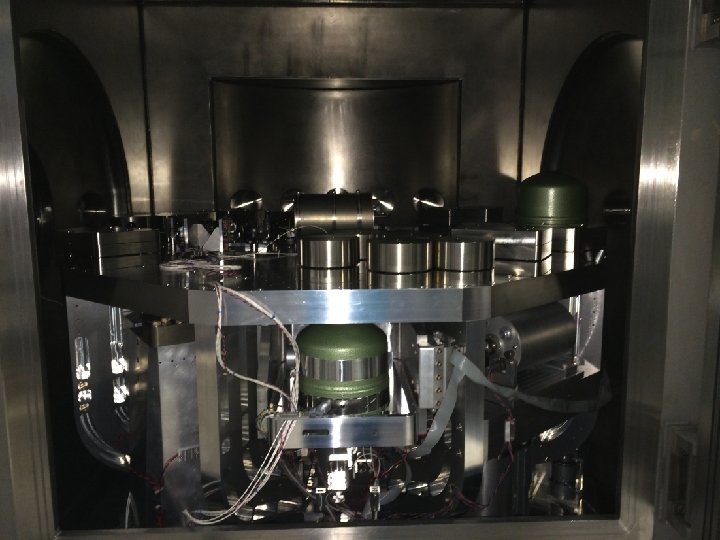
Construction well underway! Photo taken 12 March 2015 G 1500246 - Pasadena - 17 March 2015 48
![Back. Ups G 1500246 - Pasadena - 17 March 2015 49 Back. Ups G 1500246 - Pasadena - 17 March 2015 49](http://slidetodoc.com/presentation_image/5ff75a1f3fea5ea2f9a85c3c9c8cb540/image-49.jpg)
Back. Ups G 1500246 - Pasadena - 17 March 2015 49
![ISI Upper quad structure, room temp Heat shield blade springs, room temp Transmitted beam ISI Upper quad structure, room temp Heat shield blade springs, room temp Transmitted beam](http://slidetodoc.com/presentation_image/5ff75a1f3fea5ea2f9a85c3c9c8cb540/image-50.jpg)
ISI Upper quad structure, room temp Heat shield blade springs, room temp Transmitted beam shield, 80 K LIGO III end station back view model Stage 0, room temp Suspended heat shield / lower quad structure, 80 k BSC floor, room temp Beam tube shield mounted to beam tube, 80 K 50
![Vibrational modes of support structure G 1500246 - Pasadena - 17 March 2015 51 Vibrational modes of support structure G 1500246 - Pasadena - 17 March 2015 51](http://slidetodoc.com/presentation_image/5ff75a1f3fea5ea2f9a85c3c9c8cb540/image-51.jpg)
Vibrational modes of support structure G 1500246 - Pasadena - 17 March 2015 51
![Heat Shield Requirements 1) Beam tube length 2) Scattered light (much uncertainty to overcome) Heat Shield Requirements 1) Beam tube length 2) Scattered light (much uncertainty to overcome)](http://slidetodoc.com/presentation_image/5ff75a1f3fea5ea2f9a85c3c9c8cb540/image-52.jpg)
Heat Shield Requirements 1) Beam tube length 2) Scattered light (much uncertainty to overcome) G 1500246 - Pasadena - 17 March 2015 52
![Radiation leak from Beam Tube G 1500246 - Pasadena - 17 March 2015 53 Radiation leak from Beam Tube G 1500246 - Pasadena - 17 March 2015 53](http://slidetodoc.com/presentation_image/5ff75a1f3fea5ea2f9a85c3c9c8cb540/image-53.jpg)
Radiation leak from Beam Tube G 1500246 - Pasadena - 17 March 2015 53
![Light scattering noise estimates G 1500246 - Pasadena - 17 March 2015 54 Light scattering noise estimates G 1500246 - Pasadena - 17 March 2015 54](http://slidetodoc.com/presentation_image/5ff75a1f3fea5ea2f9a85c3c9c8cb540/image-54.jpg)
Light scattering noise estimates G 1500246 - Pasadena - 17 March 2015 54
![Scattered light modeling for shield • Linear regime – differential displacement between cavity and Scattered light modeling for shield • Linear regime – differential displacement between cavity and](http://slidetodoc.com/presentation_image/5ff75a1f3fea5ea2f9a85c3c9c8cb540/image-55.jpg)
Scattered light modeling for shield • Linear regime – differential displacement between cavity and scattering surface much less than light wavelength. Only worry about > 10 Hz • Nonlinear regime – differential displacement comparable to or greater than a wavelength. Upconversion is an issue, must worry about large amplitude low frequency motion. G 1500246 - Pasadena - 17 March 2015 55
![Linear regime scattered light References • T 940063 - Noise due to backscatter off Linear regime scattered light References • T 940063 - Noise due to backscatter off](http://slidetodoc.com/presentation_image/5ff75a1f3fea5ea2f9a85c3c9c8cb540/image-56.jpg)
Linear regime scattered light References • T 940063 - Noise due to backscatter off baffles, the nearby wall, and objects at the far end of the beam tube; and recommended actions – Flanagan and Thorne. – This is a useful reference for the basic theory and derivations. • T 1300354 - Scattered light noise due to the ETM coating ripple – Fritschel and Yamamoto – Good example of applying the equations in T 940063 • T 1300332 - Noise from baffle motion with the current ETM coating – Rai – Complements the example of T 1300354 G 1500246 - Pasadena - 17 March 2015 56
![Nonlinear regime scattered light References • P 1100117 - The impact of upconverted scattered Nonlinear regime scattered light References • P 1100117 - The impact of upconverted scattered](http://slidetodoc.com/presentation_image/5ff75a1f3fea5ea2f9a85c3c9c8cb540/image-57.jpg)
Nonlinear regime scattered light References • P 1100117 - The impact of upconverted scattered light on a. LIGO – Ottaway, Fritschel, and Waldman G 1500246 - Pasadena - 17 March 2015 57
![in a. LIGO Ref T 1000747 -v 4, pg 41 G 1500246 - Pasadena in a. LIGO Ref T 1000747 -v 4, pg 41 G 1500246 - Pasadena](http://slidetodoc.com/presentation_image/5ff75a1f3fea5ea2f9a85c3c9c8cb540/image-58.jpg)
in a. LIGO Ref T 1000747 -v 4, pg 41 G 1500246 - Pasadena - 17 March 2015 58
![Linear scattered light noise estimates • Small angle scatter across beam tube length – Linear scattered light noise estimates • Small angle scatter across beam tube length –](http://slidetodoc.com/presentation_image/5ff75a1f3fea5ea2f9a85c3c9c8cb540/image-59.jpg)
Linear scattered light noise estimates • Small angle scatter across beam tube length – beam tube parameters in E 940002 and P 990007 Parameters of calculation following notation in T 1300354 Calculated heat shield displacement requirement from small angle scatter G 1500246 - Pasadena - 17 March 2015 59
![Linear scattered light noise estimates • Large angle scatter in local heat shield – Linear scattered light noise estimates • Large angle scatter in local heat shield –](http://slidetodoc.com/presentation_image/5ff75a1f3fea5ea2f9a85c3c9c8cb540/image-60.jpg)
Linear scattered light noise estimates • Large angle scatter in local heat shield – assuming 150 W of local scatter out of 3 MW cavity Parameters of calculation following notation in T 1300354 Calculated heat shield displacement requirement from large angle scatter G 1500246 - Pasadena - 17 March 2015 60
![T 0900312 61 T 0900312 61](http://slidetodoc.com/presentation_image/5ff75a1f3fea5ea2f9a85c3c9c8cb540/image-61.jpg)
T 0900312 61
![10 Hz heat shield scattered light requirement T 0900312 62 10 Hz heat shield scattered light requirement T 0900312 62](http://slidetodoc.com/presentation_image/5ff75a1f3fea5ea2f9a85c3c9c8cb540/image-62.jpg)
10 Hz heat shield scattered light requirement T 0900312 62
![10 Hz heat shield scattered light requirement 10 Hz motion with 3 Hz suspension 10 Hz heat shield scattered light requirement 10 Hz motion with 3 Hz suspension](http://slidetodoc.com/presentation_image/5ff75a1f3fea5ea2f9a85c3c9c8cb540/image-63.jpg)
10 Hz heat shield scattered light requirement 10 Hz motion with 3 Hz suspension T 0900312 63
![OSEM noise 10 Hz heat shield scattered light requirement 10 Hz motion with 3 OSEM noise 10 Hz heat shield scattered light requirement 10 Hz motion with 3](http://slidetodoc.com/presentation_image/5ff75a1f3fea5ea2f9a85c3c9c8cb540/image-64.jpg)
OSEM noise 10 Hz heat shield scattered light requirement 10 Hz motion with 3 Hz suspension T 0900312 64
![KAGRA Cryo System G 1500246 - Pasadena - 17 March 2015 65 KAGRA Cryo System G 1500246 - Pasadena - 17 March 2015 65](http://slidetodoc.com/presentation_image/5ff75a1f3fea5ea2f9a85c3c9c8cb540/image-65.jpg)
KAGRA Cryo System G 1500246 - Pasadena - 17 March 2015 65
![KAGRA’s cryogenic system (pulse tube) Yusuke Sakakibara et al 2014 Class. Quantum Grav. 31 KAGRA’s cryogenic system (pulse tube) Yusuke Sakakibara et al 2014 Class. Quantum Grav. 31](http://slidetodoc.com/presentation_image/5ff75a1f3fea5ea2f9a85c3c9c8cb540/image-66.jpg)
KAGRA’s cryogenic system (pulse tube) Yusuke Sakakibara et al 2014 Class. Quantum Grav. 31 224003 G 1500246 - Pasadena - 17 March 2015 http: //iopscience. iop. org/0264 -9381/31/22/224003/ 66
![KAGRA beam tube heat shield Quote from text pages 2 -3: “In CLIO, thermal KAGRA beam tube heat shield Quote from text pages 2 -3: “In CLIO, thermal](http://slidetodoc.com/presentation_image/5ff75a1f3fea5ea2f9a85c3c9c8cb540/image-67.jpg)
KAGRA beam tube heat shield Quote from text pages 2 -3: “In CLIO, thermal radiation through the duct shield (described in section 4 ) was 1000 times larger than our expectation because we had neglected reflections from the duct shield. To reduce this heat load, donut-shaped structures (called baffles) were introduced. ”
![Annealed Pyrolitic Graphite (APG) K core technology from thermacore ~ 3 times the conductivity Annealed Pyrolitic Graphite (APG) K core technology from thermacore ~ 3 times the conductivity](http://slidetodoc.com/presentation_image/5ff75a1f3fea5ea2f9a85c3c9c8cb540/image-68.jpg)
Annealed Pyrolitic Graphite (APG) K core technology from thermacore ~ 3 times the conductivity of copper, in plane, but magnetic G 1500246 - Pasadena - 17 March 2015 68
![Annealed Pyrolitic Graphite (APG) Cu 99. 999% • See a brief video introhttps: //www. Annealed Pyrolitic Graphite (APG) Cu 99. 999% • See a brief video introhttps: //www.](http://slidetodoc.com/presentation_image/5ff75a1f3fea5ea2f9a85c3c9c8cb540/image-69.jpg)
Annealed Pyrolitic Graphite (APG) Cu 99. 999% • See a brief video introhttps: //www. youtube. com/watc h? v=k. MD 0 GUZmoy 0 • The graphite can be made flexible by making it into thin strips • Vacuum compatible, at least to NASA specs for outgassing • Conductive peak around 120 -150 K • The graphite is highly diamagnetic G 1500246 - Pasadena - 17 March 2015 http: //www. thermacore. com/thermal-basics/advanced-solid-conduction. aspx 69
![Shorter shield with cryo baffle Room temp upper structure, disconnected from cold lower Actuators Shorter shield with cryo baffle Room temp upper structure, disconnected from cold lower Actuators](http://slidetodoc.com/presentation_image/5ff75a1f3fea5ea2f9a85c3c9c8cb540/image-70.jpg)
Shorter shield with cryo baffle Room temp upper structure, disconnected from cold lower Actuators between stage 0 and heat shield Sensors between heat shield and stage 2 Gate Valve Cold link Oplevs: require steering mirrors or openings to enter shield Stage 2 80 K suspended cryo baffle St 0 80 K, non suspended beam tube shield Arm cavity baffle part of suspended HS 124 K test mass St 0 80 K heat shield and lower 70 structure
![Cold SUS structure configurations Temperature of cold part Thermal stress + alignment of warm Cold SUS structure configurations Temperature of cold part Thermal stress + alignment of warm](http://slidetodoc.com/presentation_image/5ff75a1f3fea5ea2f9a85c3c9c8cb540/image-71.jpg)
Cold SUS structure configurations Temperature of cold part Thermal stress + alignment of warm part Vibrational mode frequencies Damping of vibrational modes Relative complexity of construction 1 structure 2 structures: warm & cold Cold suspended from warm Good Low freq sus modes Fair Risky G 1500246 - Pasadena - 17 March 2015 Show stopper 71
![G 1500246 - Pasadena - 17 March 2015 72 G 1500246 - Pasadena - 17 March 2015 72](http://slidetodoc.com/presentation_image/5ff75a1f3fea5ea2f9a85c3c9c8cb540/image-72.jpg)
G 1500246 - Pasadena - 17 March 2015 72
![G 1500246 - Pasadena - 17 March 2015 73 G 1500246 - Pasadena - 17 March 2015 73](http://slidetodoc.com/presentation_image/5ff75a1f3fea5ea2f9a85c3c9c8cb540/image-73.jpg)
G 1500246 - Pasadena - 17 March 2015 73
![BSC ISI Stage 0 -1 lockers - D 1000854 Something like this could be BSC ISI Stage 0 -1 lockers - D 1000854 Something like this could be](http://slidetodoc.com/presentation_image/5ff75a1f3fea5ea2f9a85c3c9c8cb540/image-74.jpg)
BSC ISI Stage 0 -1 lockers - D 1000854 Something like this could be used to limit the suspended heat shield / lower quad structure range of motion. The design makes it impossible for the suspension to fall in the event of a wire or spring failure. Stage 1 Stage 0 G 1500246 - Pasadena - 17 March 2015 74
![Possible arrangement of lower-structure-to-upper-structure lockers considering thermal contraction Warm dimensions Cold dimensions Top view Possible arrangement of lower-structure-to-upper-structure lockers considering thermal contraction Warm dimensions Cold dimensions Top view](http://slidetodoc.com/presentation_image/5ff75a1f3fea5ea2f9a85c3c9c8cb540/image-75.jpg)
Possible arrangement of lower-structure-to-upper-structure lockers considering thermal contraction Warm dimensions Cold dimensions Top view of lower structure (square cross-section). Thermal contraction occurs along an unconstrained DOF of the lockers, for a spatially uniform lower structure temperature. The clearance in the lockers will set a requirement on the maximum thermal gradient in the 75 G 1500246 - Pasadena - 17 March 2015 structure.
![How much cooling is lost if the shield is warmer than 80 K? G How much cooling is lost if the shield is warmer than 80 K? G](http://slidetodoc.com/presentation_image/5ff75a1f3fea5ea2f9a85c3c9c8cb540/image-76.jpg)
How much cooling is lost if the shield is warmer than 80 K? G 1500246 - Pasadena - 17 March 2015 76
- Slides: 76