Low Radon Cleanroom at the University of Alberta

Low Radon Cleanroom at the University of Alberta Darren Grant, Aksel Hallin, Steve Hanchurak, Carsten Krauss, Shengli Liu, Richard Soluk

Radon Clean Laboratory Concept Tolerable Rn load = Rn scrubber flow rate times Acceptable Rn concentration = 3 m 3/min x 94 Rn/m 3 = 282 Rn/min . 00002 Bq/m 3 9. 4 222 Rn/m 3 3 m x 10 m 90 m 3 room 140 m 2 area 28 Rn/min 3 m 3/min Lights (100 cfm) emanation 23 Rn/min If walls 10 Rn/m 2 hr Radon scrubber (1 cfm) Radon scrubber Electrostatic deposition plates HEPA Cooler Baffle Leaks/diffusion 23 Rn/min 20 Bq/m 3 9. 4 x 10⁶ 222 Rn/m 3 30 m 3/min Chemical Baths? . 0002 Bq/m 3 48 Rn/min 94 222 Rn/m 3 8460 222 Rn total Class 1000 Clean Room? Lab Equipment 80 Rn/min People/ processes 80 Rn/min 2 Bq/m 3 940, 000 222 Rn/m 3 Air Lock #2 Air Lock #1 o o 9, 400 222 Rn in lungs 125, 000 222 Rn dissolved . 02 Bq/m 3 9, 400 222 Rn/m 3 K. Mc. Farlane May 16, 2006

Radon Stripping • A hybrid design will be used combining both cryogenic and pressure/vacuum swing carbon adsorption techniques • Under normal operation 3 of the tanks will be maintained at -60 C and 2 of the tanks will operate at room temperature in a pressure/vacuum swing configuration • All major components and valves are automated and will be managed by process control software

Radon Stripping Equipment • Atlas Copco GA 30+ 30 k. W water cooled compressor (180 CFM) • CD 110 desiccant drier (-70 C dewpoint) • Custom built 9 k. W water cooled process chiller (-65 C operating temperature, 4. 5 k. W cooling capacity) • Air to air heat exchanger for heat recovery, with a variable bypass to regulate chiller load and air temperature

Radon Stripping Equipment • 5 stainless steel tanks filled with approx. 200 kg each of coconut carbon • All control valves are in a custom insulated cabinet, half of which is insulated, sealed and kept at -60 C the other half is at room temperature and purged with low radon processed air • Almost all non-welded connections in the piping system will be in this 3’x 5’x 8’ cabinet

CCIS Layout • Process air will feed a sealed cleanroom in the basement of the new CCIS building (which will be completed early 2011) • A small machine shop will be installed in the cleanroom for detector fabrication • Included will be a CNC mill and lathe and both horizontal and vertical bandsaws as well as work tables and hand tools • A water purification system located outside the room will provide low radon water

Cleanroom Construction • Cleanroom is a modular design using mill finish aluminum extrusions and panels produced by Clean. Air Solutions • Basic wall panel consists of two sheets of aluminum sandwiching an aluminum foil honeycomb • Walls are 2” thick, ceiling panels use the same design but are ½” thick, standard panel size is 4’x 10’ • Cleanroom ceiling consists of a top plenum cap 10’ high which provides the outer air seal and an 8’ suspended inner ceiling holding the lights and HEPA filters

Airlock Prototype • The outer 5’x 10’ airlock has been built as a prototype to test how well this cleanroom can be sealed • Doors are hollow aluminum filled with polyurethane prehung on welded aluminum frames with compression seals and additional dogs to increase clamping force between the door and frame • The floor is sealed with a 1 cm thick layer of Precidium 550 D a spray on polyurea industrial floor coating
 • All Al-Al joints, such as wall panel seams are sealed")
Airlock Prototype (2) • All Al-Al joints, such as wall panel seams are sealed on both the inner and outer surfaces using Sika. Lastomer 511 butyl caulking • All seams are then also covered, on both the inside and outside of the airlock with a layer of Polyken 360 -17 aluminum foil backed butyl tape, this provides an additional layer of sealant and also covers the non-hardening butyl caulking

Monitoring Systems • All based on electrostatic separation and solid state detection • Currently have RAD 7 commercial detector, emanation chamber and tunnel detector running • Electronics records up to 24 channels of self triggered events. Time and energy are calculated and stored for each event

Radon Monitor: detector head and preamp box -HV Preamplifier and shaping box: Attached to detector To DAQ board Charge Sensitive S 3204 Shaping & gain 50 ohm coax.

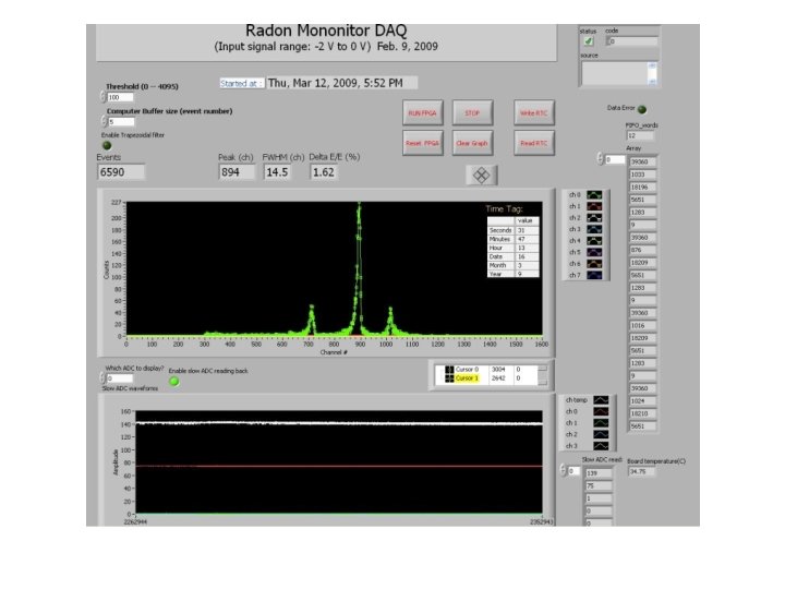
Radon Monitor: DAQ board 8 X 3 = 24 channel Preamp signals Anti alias FADC Digital Waveform Processing FPGA Trigger output 12 X 3 = 36 channel slow ADC Health Monitoring Real time Clock Micro-controller USB AD 7417*3 USB PC (Labview software)

Tunnel Detector Cross section: 20 cm x 20 cm Air velocity ~1. 8 m/s 16. 8 hours: 515 counts Po 214= 31/hour 40. 8 hours, 16490 counts= 400/hour
: : 75/hour Po 214:")
Emanation Chamber Po 210: 2. 4/hour Po 218(6114 Me. V): : 75/hour Po 214: 89/hour Po 212: 9. 6/hour 60 cm radius, 61 cm high Volume=0. 17 m**3 Po 210: 1. 25/hour Bi 212(6051 Me. V): : 3. 4/hour Po 214: 0. 3/hour Po 212: 6/hour

Emanation Rate

Calibration

Conclusions? • Radon Monitoring and radon emanation systems are well advanced and working reasonably. • Radon lab is getting into shape and will be ready and useful in 2011. • There are lots of pitfalls and snares. . .
- Slides: 22