LOGO CEPC Partial Double Ring Lattice Design and

LOGO CEPC Partial Double Ring Lattice Design and DA Study SU Feng GAO Jie WANG Dou WANG Yiwei Li Yongjun BAI Sha BIAN Tianjian GENG Huiping ZHANG Yuan Institute of High Energy Physics 高能环形正负电子对撞机相关的物理和关键技术预研究”项目启动会,2016. 9. 27

Outline I. CEPC PDR Lattice Design Progress: 1. CEPC PDR Parameter and Lattice Layout 2. CEPC PDR ARC Length Consideration and Redesign 3. CEPC PDR DA Study ( NSGAII & DA Optimization) 4. CEPC APDR Scheme 5. CEPC Double Ring Scheme 6. Summary II. CDR Report & CDR & Plan & Next to do 2

Outline 1. CEPC PDR Parameter and Lattice Layout 3
 Number of IPs Energy (Ge. V)")
Parameter for CEPC partial double ring (wangdou 20160918) Number of IPs Energy (Ge. V) Circumference (km) SR loss/turn (Ge. V) Half crossing angle (mrad) Piwinski angle Ne/bunch (1011) Bunch number Beam current (m. A) SR power /beam (MW) Bending radius (km) Momentum compaction (10 -5) IP x/y (m) Emittance x/y (nm) Transverse IP (um) x/IP y/IP VRF (GV) f RF (MHz) Nature z (mm) Total z (mm) HOM power/cavity (kw) Energy spread (%) Energy acceptance by RF (%) n Life time due to beamstrahlung_cal (minute) F (hour glass) Lmax/IP (1034 cm-2 s-1) Pre-CDR H-high lumi. H-low power W Z 2 120 54 3. 1 0 0 3. 79 50 16. 6 51. 7 6. 1 3. 4 0. 8/0. 0012 6. 12/0. 018 69. 97/0. 15 0. 118 0. 083 6. 87 650 2. 14 2. 65 3. 6 0. 13 2 6 0. 23 47 2 120 61 2. 96 15 1. 88 2. 0 107 16. 9 50 6. 2 1. 48 0. 272/0. 0013 2. 05/0. 0062 23. 7/0. 09 0. 041 0. 11 3. 48 650 2. 7 2. 95 0. 74 0. 13 2 2. 3 0. 35 37 2 120 61 2. 96 15 1. 84 1. 98 70 11. 0 32. 5 6. 2 1. 48 0. 275 /0. 0013 2. 05 /0. 0062 23. 7/0. 09 0. 042 0. 11 3. 51 650 2. 7 2. 9 0. 48 0. 13 2 2. 4 0. 34 37 2 80 61 0. 58 15 5. 2 1. 16 400 36. 5 21. 3 6. 2 1. 44 0. 1/0. 001 0. 93/0. 0078 9. 7/0. 088 0. 013 0. 073 0. 74 650 2. 95 3. 35 0. 88 0. 087 2 45. 5 61 0. 061 15 6. 4 0. 78 1100 67. 6 4. 1 6. 2 2. 9 0. 1/0. 001 0. 88/0. 008 9. 4/0. 089 0. 01 0. 072 0. 11 650 3. 78 4. 0 0. 99 0. 05 1. 7 0. 49 1. 2 0. 34 0. 68 2. 04 0. 82 3. 1 0. 82 2. 01 0. 92 4. 3 0. 93 4. 48 4

CEPC Partial Double Ring Layout 1/2 RF IP 1_ee RF RF 3. 7 Km 1/2 RF Bypass about 42 m 1/2 RF IP 4_pp IP 2_pp 1/2 RF IP 1_ee/IP 3_ee, 3. 7 Km C=60830. 4 m IP 2_pp/IP 4_pp, 1132. 8 m 4 Short Straights, 141. 6 m Bypass about 42 m RF RF 4 Medium Straights, 566. 4 m IP 3_ee 4 Long Straights, 944 m 2 Short ARC, 24*FODO, 1132. 8 m 4 Medium ARC, 112*FODO, 5286. 4 m 4 Long ARC, 124*FODO, 5852. 8 m 1/2 RF SU Feng 2016. 9. 15

CEPC Partial Double Ring Layout 12 62. 5 urad 4. 5 m 65 m B 1 357. 5 m B 2 50 7. 1 614. 4 m 7 30 m . 2 m Full crossing angle 30 mrad 15 mrad 7. 852 m Separator B 4 IP 1851. 733 m For CEPC 120 Ge. V beam: ØMax. deflection per separator is 66μrad. B 3 Version 1. 0 sufeng 2016. 9. 15

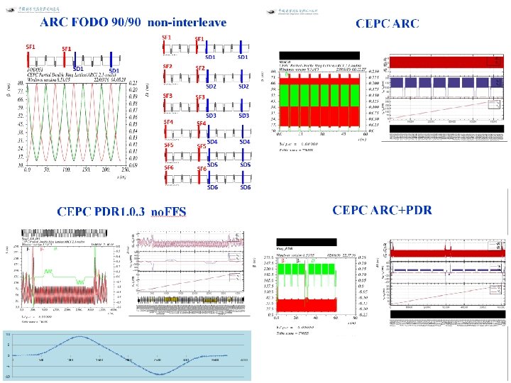
CEPC PDR 1. 0. 3 no. FFS 10 5 0 0 -5 -10 500 1000 1500 2000 2500 3000 3500 4000

Outline 2. CEPC PDR ARC Length Consideration and Redesign 8

CEPC PDR ARC Length Consideration The circumference should be also considered of SPPC requirement… 1. ARC+Straight (>= 53 Km) 2. ARC+Straight+PDR 3. ARC+Straight+PDR+FFS

CEPC & SPPC Layout
 3537. 8 m")
准直段Lattice 设计 (From Jianquan 2016. 8. 12) 3537. 8 m

CEPC ARC Length According to SPPC Theory: In Practice:

SPPC Parameter Choice and Optimize Version 201503 13

SPPC Parameter Choice and Optimize Version 201607 14
")
Emittance Increase (2. 06 nm->2. 1668 nm)

CEPC PDR 1. 0. 3 no. FFS

Parameters of Separators sufeng 201605 Separator length 4. 5 m Electrode length 4 m 1. 875 MV/m 120 Ge. V 62. 5 urad 微弧度 Number of separators per collision point 12*2=24 Total number of separators (PDR) 24*2=48 Total number of separators (APDR 6) 24*6=144 Total number of separators (APDR 8) 24*8=192 Maximum operating field strength Beam energy Maximum deflection per separator at 120 Ge. V 上限 2 MV/m

According to CEPC Pre-CDR Magnet Parameter Dipole magnets CEPC MQ Quantity 1984 Quantity 2304 Maximum field strength(T) 0. 07 Bore diameter (mm) 100 Magnetic gap (mm) 80 Field Gradient (T/m) 10 Bending angle (mrad) 3. 17 Magnetic Length (m) 2. 0 Magnetic Length (m) 18 Core width and height (mm) 700*700 Bending radius (m) 6094 Core length (mm) 1960 Good field region (mm) 100 Core cross section (W*H) (mm) 450*400 CEPC MS SD SF Quantity 992 Aperture diameter (mm) 120 Good field region (mm) 100 Super Conducting Q in CEPC IR QF QD Field Gradient (T/m) 304 309 Magnetic Length (m) 1. 25 0. 72 Peak field in coil (T) 7. 2 7. 1 Strength of sextupole field (T/m^2) 180 Coil inner diameter (mm) 40 40 Magnetic Length (m) 700 400 Coil out diameter (mm) 74 74 Cryostat diameter (mm) 400 Core width and height (mm) 520 Length of iron core (mm) 670 370 Coil mechanical length (mm) 1500 950
 ) Rho(m) Brho(E 0/")
Dipole Strength PDR 1. 0. 3 without FFS Angle(mrad L(m) ) Rho(m) Brho(E 0/ c)(T/m) B(T) Ek(Ke. V) Ke. V/m B 0 3. 205 19. 6 6115. 44 400 0. 06541 626. 349 31. 956 BSep. L -0. 0625 4. 5 -72000 400 -0. 00556 53. 2 11. 822 BMatch 1 L -8. 344 19. 6 -2348. 99 400 -0. 1702 1630. 66 83. 1967 BMatch 2 L 1. 997 19. 6 9814. 72 400 0. 0407 390. 271 19. 9118 BMatch 3 L -7. 653 19. 6 -2561. 09 400 -0. 1562 1495. 61 76. 3069 B 2 2. 1428 19. 6 9146. 91 400 0. 04373 418. 764 21. 3655 B 3 -2. 1428 19. 6 -9146. 91 400 -0. 04373 418. 764 21. 3655 BMatch 3 R 7. 653 19. 6 2561. 09 400 0. 1562 1495. 61 76. 3069 BMatch 2 R -1. 997 19. 6 -9814. 72 400 -0. 0407 390. 271 19. 9118 BMatch 1 R 8. 344 19. 6 2348. 99 400 0. 1702 1630. 66 83. 1967 BSep. R 0. 0625 4. 5 72000 400 0. 00556 53. 2 11. 822 20
 8 6 4 2 0")
CEPC PDR 1. 0. 3 with FFS (Yiwei 20160817) 8 6 4 2 0 -2 -4 -6 -8 0 500 1000 1500 2000 2500 3000 3500

CEPC ARC+PDR_FFS
")
Emittance Increase (2. 06 nm->2. 147368 nm)
 24")
Outline 3. CEPC PDR DA Study ( NSGAII & DA Optimization) 24

NSGA-II & DA Optimization Objective Variable 'npop': 500, 'ngen': 100, 'nobj': 30, 'nvar': 12, 200 CPU T 1=40 min T 2=70 h cepc_ndr_0099. txt SF 1. K 2 SF 2. K 2 SF 3. K 2 SF 4. K 2 SF 5. K 2 SF 6. K 2 SD 1. K 2 SD 2. K 2 SD 3. K 2 SD 4. K 2 SD 5. K 2 SD 6. K 2
 Betx: 80. 992367 bety: 14. 172123 2 nm Sizmax: 402.")
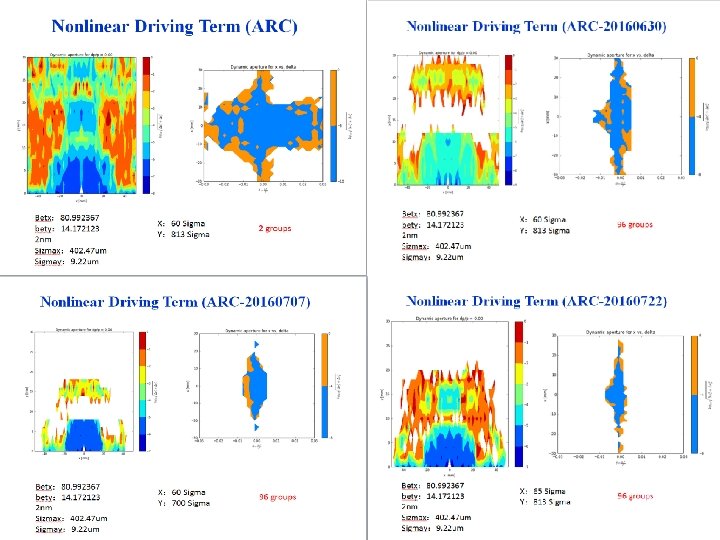
Nonlinear Driving Term (ARC) Betx: 80. 992367 bety: 14. 172123 2 nm Sizmax: 402. 47 um Sigmay: 9. 22 um X: 60 Sigma Y: 813 Sigma 2 groups
")
Nonlinear Driving Term (ARC)
 Betx: 80. 992367 bety: 14. 172123 2 nm Sizmax: 402.")
Nonlinear Driving Term (ARC_PDR_20160630) Betx: 80. 992367 bety: 14. 172123 2 nm Sizmax: 402. 47 um Sigmay: 9. 22 um X: 45 Sigma Y: 780 Sigma 2 groups
 Betx: 0. 219915 m bety: 0. 001 m")
Nonlinear Driving Term (ARC_PDR_FFS_2016. 08. 29) Betx: 0. 219915 m bety: 0. 001 m 2. 147368 nm Sizmax: 21. 731 um Sigmay: 0. 08026 um X: 46 Sigma Y: 37 Sigma 2 groups

Outline 4. CEPC APDR Scheme 31
 To solve the big problem of RF system")
New idea:Advanced PDR (APDR) To solve the big problem of RF system

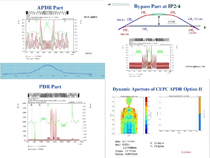
CEPC Advanced Partial Double Ring Option I 1/2 RF ARC 1 IP 1_ee RF RF 3 Km APDR 1/2 RF Bypass about 42 m IP 2_pp/IP 4_pp, 1132. 8 m APDR, 1052. 87 m IP 4_pp C=62967. 86 m IP 2_pp C=65 km APDR ARC 3 APDR RF RF 4 Long Straights, 1132. 8 m 4 ARC 3, 79*FODO, 3728. 8 m 2 ARC 4, 24*FODO, 1132. 8 m ARC 2 IP 3_ee 4 Medium Straights, 566. 4 m 4 ARC 2, 24*FODO, 1132. 8 m ARC 4 1/2 RF 4 Short Straights, 141. 6 m 4 ARC 1, 124*FODO, 5852. 8 m ARC 3 1/2 RF IP 1_ee/IP 3_ee, 2. 968 Km ARC 2 ARC 1 1/2 RF SU Feng 2016. 5. 23

CEPC Advanced Partial Double Ring Optics I PDR 1 Bypass 2 APDR PDR 3 Bypass 4 APDR

CEPC Advanced Partial Double Ring Option II RF RF IP 1_ee APDR RF ARC APDR 3. 7 Km APDR RF C=65640. 2 m RF APDR C=67 km APDR RF APDR IP 1_ee/IP 3_ee, 3703. 46 m IP 3_ee IP 2_pp/IP 4_pp, 1132. 8 m APDR, 1426 m Short Straights, 94. 4 m RF RF RF Station, 188. 8 m SU Feng ARC, 3020. 8 m 2016. 8. 15

CEPC Advanced Partial Double Ring Optics II PDR 1 APDR 3 APDR APDR

Outline 5. CEPC Double Ring Scheme 38

RF station C=61 km ? RF station

Double Ring Scheme e-ring IP 1 IP 2 Bypass 42 m IP 3 IP 4 Bypass 42 m

Outline 6. Summary u The first version of CEPC Partial Double Ring Lattice was designed (Version 1. 0). The whole length of CEPC PDR is 3781. 27 m, full crossing angle is 30 mrad, maximum distance between two ring is 14. 913 m. u The Dynamic Aperture need to be optimized. Now the DA of CEPC with PDR and Bypass(at IP 2/4) and without FFS is better than before, but the DA with FFS is not good enough. u The linear lattice of PDR may also be optimized. 41

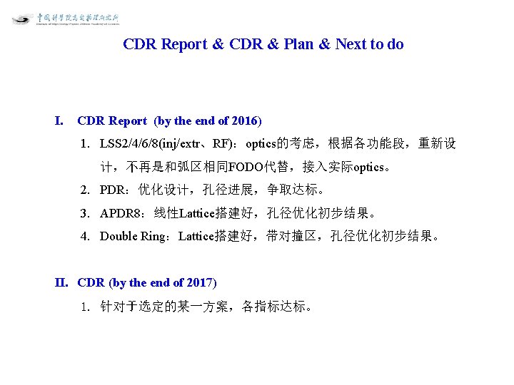
Outline I. II. CDR Report & CDR & Plan & Next to do 42

CEPC_ARC_PDR_IR_96 fam_damp 0. 8 mm 5 um 21. 731 um 0. 08026 um 37 Sigma. X 63 Sigma. Y

DA result • Dynamic aperture result – W/O error of the magnets – Synchrotron motion included, w/ damping – Tracking with 100 turns – Coupling factor =0. 003 for y – Working point (0. 08, 0. 22) DAx Yiwei Wang DAy CEPC预研项目启动会 46

LOGO 47

Acknowledge • The authors would thank Frank Schmidt very much for the help in Six. Track and Dynamic Aperture Study. • Thanks for Gang Xu, Qing Qin, Yuan Zhang, Yuemei Peng, Qingjin Xu, Xiaohao Cui, Zhe Duan and Yudong Liu’s kind help and beneficial discussion! 48

Reference 1. F. Zimmermann, “HE-LHC & VHE-LHC accelerator overview (injector chain and main parameter choices)”, Report of the Joint Snowmass. Eu. CARD/Acc. Net-Hi. Lumi LHC meeting, Switzerland, 2013. 2. F. Zimmermann et al. , “FCC-ee overview”, in Proc. HF 2014, Beijing, China, Sep. 2014, p. 6 -15. 3. Layout and Performance, in LHC Design Report Volume 1, European Organization for Nuclear Research, 2004, p 21 -22. 4. The Science of the CEPC and the SPPC, in CEPC-SPPC: Pre-CDR, Volume II - accelerator, The CEPC-SPPC Study Group, Mar. 2015, p. 28 -35. 5. J. Gao, “Review of some important beam physics issues in electron positron collider designs”, Modern Physics Letters A, Vol. 30, No. 11, p. 1530006, 2015. 6. F. Su et al. , “Method study of parameter choice for a circular proton-proton collider”, Chinese Physics C, Vol. 40, No. 1, p. 017001, 2016. 7. D. Wang et al. , “Optimization Parameter Design of a Circular e+e- Higgs Factory”, Chinese Physics C, Vol. 37, No. 9, p. 97003 -0970, 2013. 8. M. Xiao et al. , “Study on CEPC performances with different collision energies and geometric layouts”, Chinese Physics C, Vol. 40, No. 8, 2016. 9. F. Su, J. Gao et al, “SPPC Parameter Choice and Lattice Design”, TUPMW 001, Proceedings of IPAC 2016. 10. F. Su, J. Gao et al, “CEPC Partial Double Ring Lattice Design”, THPOR 009, Proceedings of IPAC 2016. 11. F. Su, J. Gao, etc. , “CEPC partial double ring lattice design and SPPC lattice design”, IAS White Paper, submitted for publication, Apr. 2016. 12. F. Schmidt, “Dynamic Aperture in large Proton Accelerators”, ”A Talk on DA study in IHEP”, May 2016. 13. Oide, FCC-ee_150917. 14. P. Raimondi, Status on Super. B effort, La Thuile, March 11, 2006. 15. Kalbreier, et al, “Layout, design and construction of the electrostatic separation system of the LEP e+e- collider”, CERN, Geneva, Switzerland. 16. R. Martin, et al, “Status of the FCC-ee interaction region design”, HF 2014 Workshop, Beijing, China, 9 -12 October, 2014. 49
- Slides: 49