LOGO Arduino Sketch RTOS Arduino Uno Interrupt timer
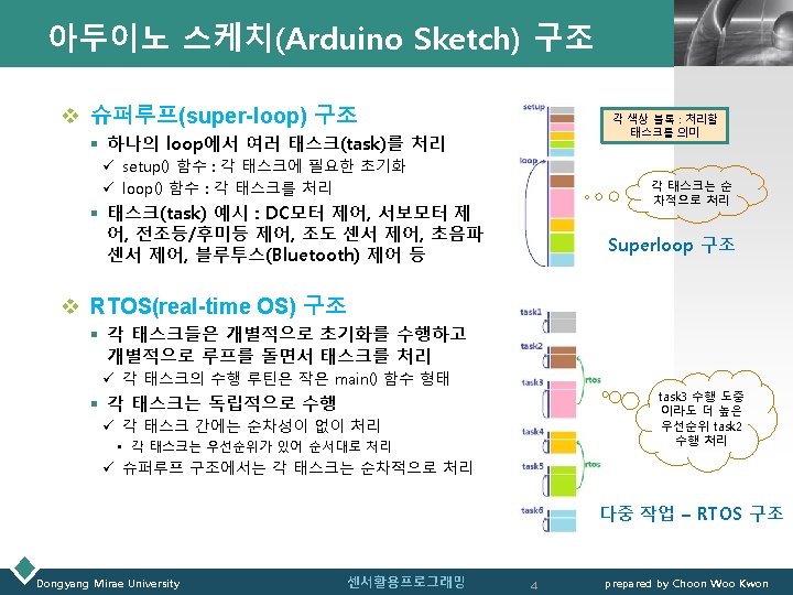
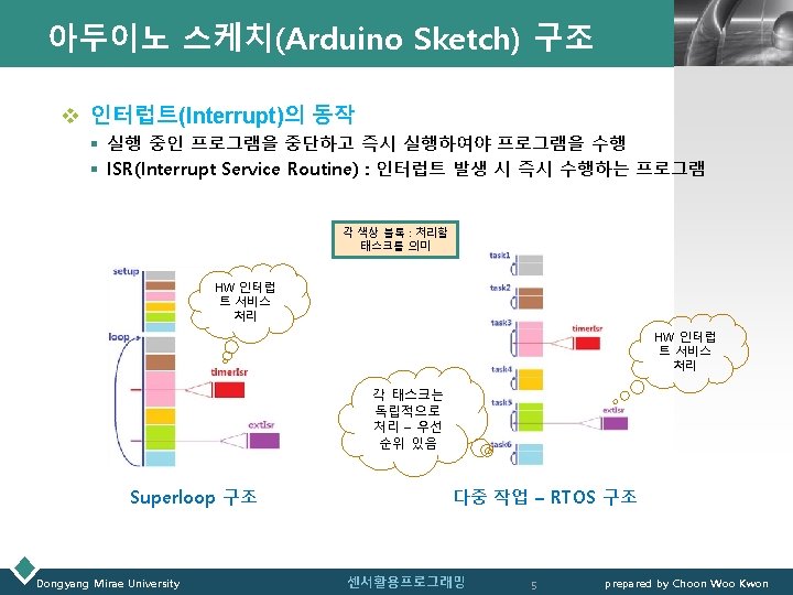
 구조 § 슈퍼루프 구조와 RTOS 구조 ØArduino Uno 인터럽트(Interrupt)")


 배선도/회로도 Dongyang Mirae University 센서활용프로그래밍 16 LOGO prepared by Choon Woo Kwon")
 – 스케치(1) // Blink 루틴과 Fading 루틴을 단순히 합친 경우(p. 59) //")
 – 스케치(2) // millis() 함수를 이용하여 Blink 기능 수행 // delay() 함수")
 – 스케치(3)LOGO // millis() 함수를 이용하여 Blink 기능, Fading 기능 구현 //")
 – 스케치(3)LOGO // (… 이전 슬라이드 스케치에서 연속 …) void fading_loop() {")
 – millis() 동작LOGO millis() 함수 이용 LED BLINK current. Millis=millis() (예) blink_interval=500")
 Dongyang Mirae University 센서활용프로그래밍 22 prepared by Choon Woo Kwon")
 LOGO v Arduino Uno : ATmega 328 § T/C : 타이머(timer)/카운터(Counter)")


 - p. 140 LOGO v 아두이노 보드의 인터럽트 Arduino int 0 int")
 – ATmega 328 DATASHEETLOGO v 11. 7. Reset and Interrupt Handling(DATASHEET p. 32)")
 – ATmega 328 datasheet LOGO • There are basically two types of interrupts:")
 – ATmega 328 datasheet LOGO § The following example shows how this can")
 – LED Blink 간격 구현 LOGO v 예시(1) 배치도 //")
 – ISR과 loop의 공유문제(p. 76) // ISR(Interrupt Service Routine)과")
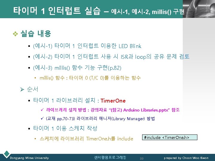
 – millis() 함수 기능 구현(p. 82)LOGO // 타이머 1 인터럽트를")
 Dongyang Mirae University 센서활용프로그래밍 38 prepared by")

- Slides: 39
목차 LOGO Ø아두이노 스케치(Arduino Sketch) 구조 § 슈퍼루프 구조와 RTOS 구조 ØArduino Uno 인터럽트(Interrupt) § 타이머 인터럽트 : timer 0, timer 1 § 외부 인터럽트 § timer. Isr과 loop()의 공유영역 문제 Dongyang Mirae University 센서활용프로그래밍 2 prepared by Choon Woo Kwon
LOGO 아두이노 스케치 구조 Dongyang Mirae University 센서활용프로그래밍 3 prepared by Choon Woo Kwon
LOGO Arduino Uno R 3 Microcontroller : ATmega 328 P Dongyang Mirae University 센서활용프로그래밍 6 prepared by Choon Woo Kwon
Microcontroller : ATmega 328 P LOGO v Arduino Uno R 3 적용 Microcontroller ü ATmega 328 P : low-power CMOS 8 -bit microcontroller ü AVR CPU : RISC 구조 v Atmel® ATmega 328 P 특징 ü Advanced RISC Architecture • • • 131 Powerful Instructions Most Single Clock Cycle Execution 32 x 8 General Purpose Working Registers Fully Static Operation Up to 20 MIPS Throughput at 20 MHz On-chip 2 -cycle Multiplier ü High Endurance Non-volatile Memory Segments • • Arduion Uno R 3와 AVR CPU 32 KBytes of In-System Self-Programmable Flash program Memory 1 KBytes EEPROM 2 KBytes Internal SRAM Write/Erase Cycles: 10, 000 Flash/100, 000 EEPROM Data Retention: 20 years at 85°C/100 years at 25°C Optional Boot Code Section with Independent Lock Bits Programming Lock for Software Security ü Atmel® QTouch® Library Support • Capacitive Touch Buttons, Sliders and Wheels • QTouch and QMatrix® Acquisition • Up to 64 sense channels Dongyang Mirae University 센서활용프로그래밍 Pin 구성 (28 -pin PDIP 패키지) 7 prepared by Choon Woo Kwon
Microcontroller : ATmega 328 P LOGO v Atmel ® ATmega 328 P 특징 ü Peripheral Features • • Two 8 -bit Timer/Counters, One 16 -bit Timer/Counter Real Time Counter(RTC) Six PWM Channels 6 -channel 10 -bit ADC (PDIP Package) § 8 -channel 10 -bit ADC (TQFP and QFN/MLF package) Two Master/Slave SPI Serial Interface One Programmable Serial USART § One Byte-oriented 2 -wire Serial Interface Programmable Watchdog Timer Interrupt and Wake-up on Pin Change ü Special Microcontroller Features • Power-on Reset and Programmable Brown-out Detection • Internal Calibrated Oscillator • External and Internal Interrupt Sources ü Six Sleep Modes: Idle • ADC Noise Reduction, Power-save, Power-down, Standby, Extended Standby ü I/O and Packages • 23 Programmable I/O Lines • 28 -pin PDIP, 32 -lead TQFP, 28 -pad QFN/MLF, 32 -pad QFN/MLF ü Operating Voltage : 1. 8 - 5. 5 V Dongyang Mirae University 센서활용프로그래밍 8 prepared by Choon Woo Kwon
Microcontroller : ATmega 328 P LOGO v Atmel ATmega 328 Block Diagram(AVR CPU ATmega 328 P) Dongyang Mirae University 센서활용프로그래밍 Pin 구성 (28 -pin PDIP 패키지) 9 prepared by Choon Woo Kwon
Microcontroller : ATmega 328 P LOGO v Atmel ® ATmega 328 P 메모리 § 메모리 공간(Memory Space) ü 데이터/프로그램 메모리 공간 ü EEPROM 메모리 : 데이터 저장 § 메모리 형태 ü 플래시 메모리(flash memory) – 프로그램 메모리 플래시 메모리 (flash memory) • 32 KByte : AVR 명령어 16/32 bit이어서 (16 K x 16)로 구성 • 2개 section으로 구분 § Boot Loader section & Application Program section • 플래시 메모리 수명 : 10, 000 write/erase cycles • 주소 영역 : PC(protram counter)가 14 -bit 폭 § 프로그램 메모리 주소 : 16 K 주소 크기 ü SRAM - 데이터 메모리 • 하위 2303개 메모리 주소(lower data memory locations) § 내부 데이터(internal data) 처리용 SRAM(2 K) § I/O 레지스터(register) : 내장된 I/O 장치들을 제어. I/O 명령 어를 사용(memory mapped I/O) » 범용 Register(32) : bit addressing 가능 » I/O Register(64) § 확장 I/O Register(160) : I/O 명령어 사용 못하고 일반 메모리 에 사용하는 명령어 사용 SRAM 데이터 메모리 ü EEPROM - 데이터 메모리 • EEPROM Read/Write 접근 : 별도 Register를 통해 I/O 공간 에서 접근 가능(1 Kbyte 크기) Dongyang Mirae University 센서활용프로그래밍 10 prepared by Choon Woo Kwon
Arduino Uno R 3 CPU : ATmega 328/P LOGO v Atmel ATmega 328 Configuration 요약 Dongyang Mirae University 센서활용프로그래밍 11 prepared by Choon Woo Kwon
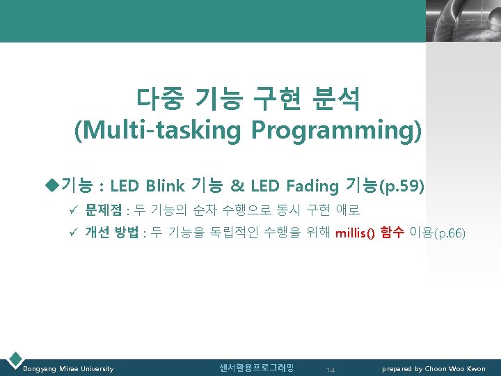
LOGO 아두이노 슈퍼루프 프로젝트 - 다중 기능 구현 분석 - Dongyang Mirae University 센서활용프로그래밍 12 prepared by Choon Woo Kwon
Multi-tasking 실습 : Blink+Fading LOGO v 실습 준비 Arduino UNO Breadboard 저항 330 Ω LED(Red) Dongyang Mirae University LED(Yellow) 센서활용프로그래밍 15 prepared by Choon Woo Kwon
Multi-tasking 실습(Blink+Fading) 배선도/회로도 Dongyang Mirae University 센서활용프로그래밍 16 LOGO prepared by Choon Woo Kwon
Multi-tasking 실습(Blink+Fading) – 스케치(1) // Blink 루틴과 Fading 루틴을 단순히 합친 경우(p. 59) // Blink, Fading 두 기능이 순차적으로 처리 // Blink 동작을 Fading 루틴 사이에 삽입 (p. 62) // Blink, Fading 기능이 상호 연동이 되어 동작 int led. Pin_fading = 11; int led. Pin_blink = 13; void setup() { pin. Mode(led. Pin_fading, OUTPUT); pin. Mode(led. Pin_blink, OUTPUT); } void loop() { //Blink 루틴 시작 digital. Write(led. Pin_blink, HIGH); delay(1000); digital. Write(led. Pin_blink, LOW); delay(1000); // Fading 루틴 시작 for(int fade. Value = 0; fade. Value <= 255; fade. Value +=5) { analog. Write(led. Pin_fading, fade. Value); delay(30); } for(int fade. Value = 255; fade. Value >= 0; fade. Value -=5) { analog. Write(led. Pin_fading, fade. Value); delay(30); } } Dongyang Mirae University LOGO void loop() { // fading up for(int fade. Value = 0; fade. Value <= 255; fade. Value +=5) { analog. Write(led. Pin_fading, fade. Value); digital. Write(led. Pin_blink, HIGH); delay(30); } // fading down for(int fade. Value = 255; fade. Value >= 0; fade. Value -=5) { analog. Write(led. Pin_fading, fade. Value); digital. Write(led. Pin_blink, LOW); delay(30); } } 센서활용프로그래밍 17 prepared by Choon Woo Kwon
Multi-tasking 실습(Blink+Fading) – 스케치(2) // millis() 함수를 이용하여 Blink 기능 수행 // delay() 함수 사용 않음 int led. Pin_fading = 11; int led. Pin_blink = 13; void loop() { // millis 함수로 현재 시간 얻기 unsigned long current. Millis = millis(); Serial. println(current. Millis); if(current. Millis-previous. Millis >= interval) { previous. Millis = current. Millis; int led. State = LOW; long previous. Millis = 0; if(led. State == LOW) led. State = HIGH; else led. State = LOW; long interval = 1000; void setup() { Serial. begin(115200); pin. Mode(led. Pin_fading, OUTPUT); pin. Mode(led. Pin_blink, OUTPUT); LOGO digital. Write(led. Pin_blink, led. State); } } } Dongyang Mirae University 센서활용프로그래밍 18 prepared by Choon Woo Kwon
Multi-tasking 실습(Blinking+Fading) – 스케치(3)LOGO // millis() 함수를 이용하여 Blink 기능, Fading 기능 구현 // 각 기능을 독립적으로 설정 가능 void blink_loop() { // millis 함수로 현재 시간 얻기 unsigned long current. Millis = millis(); void setup() { blink_setup(); fading_setup(); } if(current. Millis-blink_previous. Millis >= blink_interval) { blink_previous. Millis = current. Millis; if(blink_led. State == LOW) blink_led. State = HIGH; else blink_led. State = LOW; void loop() { blink_loop(); fading_loop(); } 매 blink _interval(500 ms) 마다 토글(toggle)되는 blink_led. State를 출력 digital. Write(led. Pin_blink, blink_led. State); } int led. Pin_blink = 13; } //led. State, previous. Millis, blink_interval 변수는 전역변수로 스케 치 파일 내 모든 함수에서 참조 가능 //(… 다음 슬라이드 스케치로 연속 …) int blink_led. State = LOW; long blink_previous. Millis = 0; long blink_interval = 500; void blink_setup() { pin. Mode(led. Pin_blink, OUTPUT); } Dongyang Mirae University 센서활용프로그래밍 19 prepared by Choon Woo Kwon
Multi-tasking 실습(Blinking+Fading) – 스케치(3)LOGO // (… 이전 슬라이드 스케치에서 연속 …) void fading_loop() { unsigned long current. Millis = millis(); //fading. Value, fading. Dir, previous. Millis, fading_interval 등은 전 역변수로 스케치 파일 내 모든 함수에서 참조 가능 if(current. Millis-fading_previous. Millis >= fading_interval) { fading_previous. Millis = current. Millis; int led. Pin_fading = 11; int fading. Value = 0; int fading. Dir = 1; long fading_previous. Millis = 0; long fading_interval = 30; if(fading. Dir == 1) { if(fading. Value <= 255) { fading. Value +=3; if(fading. Value > 255) { fading. Value = 255; void fading_setup() { pin. Mode(led. Pin_fading, OUTPUT); } 매 fading _interval(30 ms) 마다 fading_DIR에 따라 증가 또는 감소하는 fading_Value(0~255)를 PWM 출력 fading. Dir = 0; } } } else { if(fading. Value >= 0) { fading. Value -=3; if(fading. Value < 0) { fading. Value = 0; fading. Dir = 1; } } } analog. Write(led. Pin_fading, fading. Value); } } Dongyang Mirae University 센서활용프로그래밍 20 prepared by Choon Woo Kwon
Multi-tasking 실습(Blinking+Fading) – millis() 동작LOGO millis() 함수 이용 LED BLINK current. Millis=millis() (예) blink_interval=500 경우 0 1 2 ︙ ︙ 498 499 500 501 502 ︙ 998 999 1000 1001 1002 ︙ ︙ 1498 1499 1500 1501 1502 ︙ current. Millis 값이 매 interval 값에 도달할 때마다 § LED 상태 값을 토글 ON ⇔ OFF § LED 상태 값을 아두이노 Pin을 통해 출력 current. Millis 값이 interval에 도 달 않은 경우 § 출력 없음 current. Millis 값이 500, 1000, 1500, … 이 될 때 LED 상태가 토글 되면서 상태 값이 출력 ⇒ LED 0. 5초 ON, 0. 5초 OFF 깜박거림 Dongyang Mirae University millis() 함수 이용 LED FADING current. Millis=millis() 0 1 2 ︙ 29 30 31 ︙ 59 60 61 ︙ 89 90 91 ︙ 119 120 121 ︙ 149 150 151 ︙ 179 180 181 ︙ 센서활용프로그래밍 (예) fading_interval=30 경우 current. Millis 값이 매 interval이 될 때마다 § LED Fading이 UP 또는 DOWN 방향 으로 1개의 fade. Value 값을 PWM 출 력으로 수행 fade. Value 값이 PWM 출력범위 0, 255을 벗어나면 Fading 방향 값을 토글 FADING UP ⇔ FADING DOWN current. Millis 값이 interval에 도달 않 은 경우 § 출력 없음 current. Millis 값이 30, 60, 90, 120, …이 될 때 PWM 출력 값으로 사용되는 fade. Value 가 fade. Dir 상태(UP/DOWN)에 따라 값이 증가/감소되며 fade. Value 값이 PWM 출력 § fade. Value는 0~255으로 제한되며 범위 를 벗어나면 fade. Dir이 토글 ⇒ LED는 매 30 ms마다 1개의 fade. Value가 일정크기(예제 경우 ± 3) 증가 또는 감소하 여 PWM 출력 값으로 출력. ⇒ LED는 30 ms 간격으로 일정크기 밝기로 증가 또는 감소 21 prepared by Choon Woo Kwon
LOGO Arduino Uno 인터럽트(Interrupt) Dongyang Mirae University 센서활용프로그래밍 22 prepared by Choon Woo Kwon
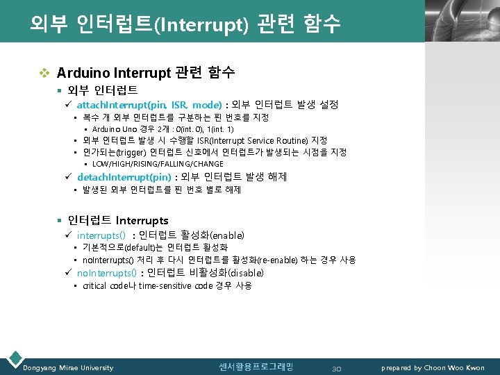
Arduino Uno 인터럽트(Interrupt) LOGO v Arduino Uno : ATmega 328 § T/C : 타이머(timer)/카운터(Counter) • 펄스 발생, 외부 이벤트 발생 횟수 측정, PWM 신호 생성 ü T/C Module : 3개 • 8 bit T/C 0, 16 bit T/C 1, 8 bit T/C 2 • 인터럽트 발생 가능 § 인터럽트(interrupt) • HW 인터럽트 : 전원차단, 인위적 하드웨어 조작 • SW 인터럽트 : 프로그램이 발생(zero divide, overflow 등) Ø 인터럽트 벡터 크기 : 2 instruction words ü HW 인터럽트 • 내부 인터럽트 : TC(Timer/Counter) 인터럽트 § T/C 0, T/C 1, T/C 2 : 인터럽트 발생 신호 주기 설정 가능 • 외부 인터럽트(2개) : pin #2, pin #3 • • • Dongyang Mirae University SPI : Serial Peripheral Interface TWI : 2 -wire Serial Interface USART : Universal Synchronous Asynchronous Receiver Transceiver 센서활용프로그래밍 23 prepared by Choon Woo Kwon
타이머 인터럽트 : timer 0 – p. 69 LOGO ATmega 328 Timer Module § 8 bit T/C 0 § 16 bit T/C 1 § 8 bit T/C 2 Timer 0 Interrupt § 8 bit T/C 0 module § 1초 1000번 발생 : millis() § ISR : SRAM에 카운터 변수를 두고 인터 럽트 발생마다 1씩 증가 Flash 메모리 내 수행 중인 프로그램 (Syntax) millis() ü Return 값 : Arduino board가 현재 프로그램을 시작한 후의 시간(msec) 약 50일 이후는 0값 return (overflow) ü (return 값-unsigned long ) Dongyang Mirae University 센서활용프로그래밍 24 prepared by Choon Woo Kwon
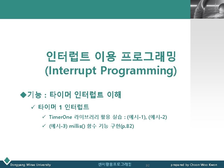
타이머 인터럽트 : timer 1 – p. 71 LOGO ATmega 328 Timer Module § 8 bit T/C 0 § 16 bit T/C 1 § 8 bit T/C 2 Timer 1 Interrupt § 16 bit T/C 1 module § 발생 신호 주기 : 임의 설정 가능 § ISR : Timer. One 라이브러리 설치 필요 #include <Timer. One. h> void setup() { Serial. begin(115200); Timer 1. initialize(1000); Timer 1. attach. Interrupt(timer. Isr); } void loop() { Serial. println("| "); } void timer. Isr() { Serial. println(" ]"); } Dongyang Mirae University 센서활용프로그래밍 직렬통신 속도 115200 bps 1000 us=1 ms=1/1000초 초당 1000번 인터럽트 발생: time. Isr() 호출 |, space, newline을 차례로 출력 space, ], newline을 차례로 출력 25 prepared by Choon Woo Kwon
외부 인터럽트(Interrupt) - p. 140 LOGO v 아두이노 보드의 인터럽트 Arduino int 0 int 1 int 2 int 3 int 4 int 5 Uno, Nano, Mini (328 -based) 2 3 Mega, Mega 2560, Mega. ADK 2 3 21 20 19 18 Leonardo, Micro (32 u 4 -based) 3 2 0 1 7 Due, 101 모든 디지털 핀 v Arduino Uno R 3의 외부 인터럽트 § 외부 인터럽트 ü 외부 인터럽트 0(int 0) : pin #2 ü 외부 인터럽트 1(int 1) : pin #3 ※ GPIO : General Purpose Input/Output ü CPU 핀(pin)을 입력 또는 출력으로 사용 가능 ü Arduino 경우 : 0 V, 5 V로 I/O 가능 • 출력 모드 : 핀을 통해서 0 V 혹은 5 V 출력 • 입력 모드 : 0 V 혹은 5 V 전압 입력 § Digital 경우 HIGH/LOW, Analog 경우 0~1023 값으로 변환 Dongyang Mirae University 센서활용프로그래밍 26 prepared by Choon Woo Kwon
인터럽트(Interrupt) – ATmega 328 DATASHEETLOGO v 11. 7. Reset and Interrupt Handling(DATASHEET p. 32) • The AVR provides several different interrupt sources. These interrupts and the separate Reset Vector each have a separate program vector in the program memory space. All interrupts are assigned individual enable bits which must be written logic one together with the Global Interrupt Enable bit in the Status Register in order to enable the interrupt. Depending on the Program Counter value, interrupts may be automatically disabled when Boot Lock bits BLB 02 or BLB 12 are programmed. This feature improves software security. • The lowest addresses in the program memory space are by default defined as the Reset and Interrupt Vectors. They have determined priority levels: The lower the address the higher is the priority level. RESET has the highest priority, and next is INT 0 – the External Interrupt Request 0. The Interrupt Vectors can be moved to the start of the Boot Flash section by setting the IVSEL bit in the MCU Control Register (MCUCR). The Reset Vector can also be moved to the start of the Boot Flash section by programming the BOOTRST Fuse. • When an interrupt occurs, the Global Interrupt Enable I-bit is cleared and all interrupts are disabled. The user software can write logic one to the I-bit to enable nested interrupts. All enabled interrupts can then interrupt the current interrupt routine. The I-bit is automatically set when a Return from Interrupt instruction – RETI – is executed. Dongyang Mirae University 센서활용프로그래밍 27 prepared by Choon Woo Kwon
인터럽트(Interrupt) – ATmega 328 datasheet LOGO • There are basically two types of interrupts: • The first type is triggered by an event that sets the Interrupt Flag. For these interrupts, the Program Counter is vectored to the actual Interrupt Vector in order to execute the interrupt handling routine, and hardware clears the corresponding Interrupt Flags can also be cleared by writing a logic one to the flag bit position(s) to be cleared. If an interrupt condition occurs while the corresponding interrupt enable bit is cleared, the Interrupt Flag will be set and remembered until the interrupt is enabled, or the flag is cleared by software. Similarly, if one or more interrupt conditions occur while the Global Interrupt Enable bit is cleared, the corresponding Interrupt Flag(s) will be set and remembered until the Global Interrupt Enable bit is set, and will then be executed by order of priority. • The second type of interrupts will trigger as long as the interrupt condition is present. These interrupts do not necessarily have Interrupt Flags. If the interrupt condition disappears before the interrupt is enabled, the interrupt will not be triggered. When the AVR exits from an interrupt, it will always return to the main program and execute one more instruction before any pending interrupt is served. • The Status Register is not automatically stored when entering an interrupt routine, nor restored when returning from an interrupt routine. This must be handled by software. • When using the CLI instruction to disable interrupts, the interrupts will be immediately disabled. No interrupt will be executed after the CLI instruction, even if it occurs simultaneously with the CLI instruction. Dongyang Mirae University 센서활용프로그래밍 28 prepared by Choon Woo Kwon
인터럽트(Interrupt) – ATmega 328 datasheet LOGO § The following example shows how this can be used to avoid interrupts during the timed EEPROM write sequence. § Assembly Code Example in r 16, SREG ; store SREG value cli ; disable interrupts during timed sequence sbi EECR, EEMPE ; start EEPROM write sbi EECR, EEPE out SREG, r 16 ; restore SREG value (I-bit) § C Code Example char c. SREG; c. SREG = SREG; /* store SREG value */ /* disable interrupts during timed sequence */ _CLI(); EECR |= (1<<EEMPE); /* start EEPROM write */ EECR |= (1<<EEPE); SREG = c. SREG; /* restore SREG value (I-bit) */ § Note: Please refer to About Code Examples. § When using the SEI instruction to enable interrupts, the instruction following SEI will be executed before any pending interrupts, as shown in this example. § Assembly Code Example sei ; set Global Interrupt Enable sleep ; enter sleep, waiting for interrupt ; note: will enter sleep before any pending interrupt(s) § C Code Example __enable_interrupt(); /* set Global Interrupt Enable */ __sleep(); /* enter sleep, waiting for interrupt */ /* note: will enter sleep before any pending interrupt(s) */ Dongyang Mirae University 센서활용프로그래밍 29 prepared by Choon Woo Kwon
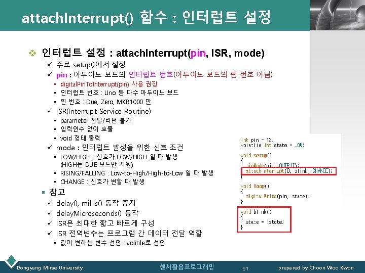
타이머 1 인터럽트 예시(1) – LED Blink 간격 구현 LOGO v 예시(1) 배치도 // // 예시(1) : 타이머 1 인터럽트를 이용하여 LED Blink // // Timer. One 라이브러리 사용을 위해 라이브러리 #include <Timer. One. h> void setup() { pin. Mode(13, OUTPUT); Timer 1. initialize(2000000); //타이머 간격을 2초로 설정 //2000000 us=2000 ms=2 sec Timer 1. attach. Interrupt(timer. Isr); //타이머 1 인터럽트 처리기 } void loop() {} // 인터럽트 처리기(Interrupt Service Routine) void timer. Isr() { digital. Write(13, digital. Read(13) ^ 1); //LED 토글 } /* 참고 : 비트연산자(Bitwise Operators) & (bitwise and) | (bitwise or) ^ (bitwise xor) ~ (bitwise not) << (bitshift left) >> (bitshift right) */ Dongyang Mirae University 센서활용프로그래밍 34 prepared by Choon Woo Kwon
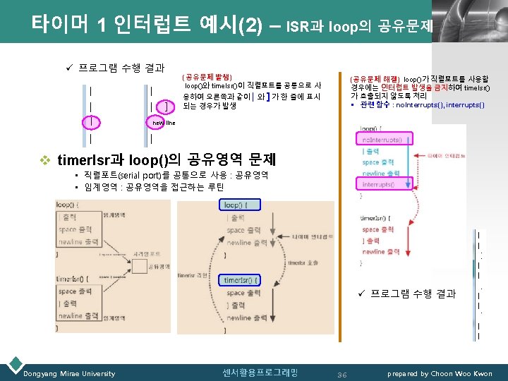
LOGO 타이머 1 인터럽트 예시(2) – ISR과 loop의 공유문제(p. 76) // ISR(Interrupt Service Routine)과 loop의 공유문제 발생 // // 타이머 1 인터럽트를 이용 // // Timer. One 라이브러리 사용을 위해 라이브러리 #include <Timer. One. h> // ISR(Interrupt Service Routine)과 loop의 공유문제 해결 // // 타이머 1 인터럽트를 이용 // // Timer. One 라이브러리 사용을 위해 라이브러리 #include <Timer. One. h> void setup() { Serial. begin(115200); Timer 1. initialize(1000); Timer 1. attach. Interrupt(timer. Isr); } void loop() { Serial. println("| "); } void setup() { Serial. begin(115200); Timer 1. initialize(1000); Timer 1. attach. Interrupt(timer. Isr); } void loop() { no. Interrupts(); 인터럽트 발생 금지 Serial. println("| "); interrupts(); 인터럽트 발생 허용 } void timer. Isr() { Serial. println(" ]"); } 직렬통신 속도 115200 bps 1000 us=1 ms=1/1000초 초당 1000번 인터럽트 발생: time. Isr() 호출 |, space, newline을 차례로 출력 space, ], newline을 차례로 출력 void timer. Isr() { Serial. println(" ]"); } (수행결과) |, space, newline space ] 을 차례로 출력 (수행결과) | space, ] 이 한 줄에 표시되는 경우 발생 Dongyang Mirae University 센서활용프로그래밍 35 prepared by Choon Woo Kwon
타이머 1 인터럽트 예시(3) – millis() 함수 기능 구현(p. 82)LOGO // 타이머 1 인터럽트를 이용 millis() 함수 기능 구현 // // 타이머 1 인터럽트를 이용 // #include <Timer. One. h> void setup() { Serial. begin(115200); (수행결과) millis() 함수와 동일한 결과 출력 직렬통신 속도 115200 bps 1000 us=1 ms=1/1000초 Timer 1. initialize(1000); 초당 1000번 인터럽트 발생: Timer 1. attach. Interrupt(timer. Isr); time. Isr() 호출 } space, ], newline을 차례로 출력 void loop() { unsigned long current. Millis = get_millis(); Serial. println(current. Millis); } unsigned long timer 1_millis = 0; void timer. Isr() { timer 1_millis ++; } timer 1_millis 변수 값을 초당 1000번 증가 unsigned long get_millis(void) { return timer 1_millis; } Dongyang Mirae University 센서활용프로그래밍 37 prepared by Choon Woo Kwon
LOGO 아두이노 슈퍼루프 프로젝트 아두이노 프로젝트(p. 84) Dongyang Mirae University 센서활용프로그래밍 38 prepared by Choon Woo Kwon
LOGO Dongyang Mirae University 센서활용프로그래밍 39 prepared by Choon Woo Kwon