Logic Gates Logic Gates A logic gate is


 gate � The XOR ( exclusive-OR ) gate acts in")
 gate � Another way of looking at this circuit is")
 gate XOR gate Input 1 Input 2 Output 0 0")
 gate � The XNOR (exclusive-NOR) gate is a combination XOR gate followed")
 gate Input 1 Input 2 Output 0 0 1 0")


 Perform all inversions")
 � Determine the output x given A=0,")
(B’+C)")

(B’+C)")


- Slides: 40
Logic Gates
Logic Gates � A logic gate is an elementary building block of a digital circuit. � Most logic gates have two inputs and one output. � At any given moment, every terminal is in one of the two binary conditions low (0) or high (1), represented by different voltage levels.
Boolean Constants and Variables � Boolean 0 and 1 do not represent actual numbers but instead represent the state, or logic level. Logic 0 False Off Low No Open switch Logic 1 True On High Yes Closed switch
Three Basic Logic Operations � OR � AND � NOT � Other derived logic operations � NOR � NAND � XOR � XNOR
Truth Tables � A truth table is a means for describing how a logic circuit’s output depends on the logic levels present at the circuit’s inputs. Inputs A 0 0 1 1 B 0 1 Output x 1 0 A ? B x
OR Gate � The OR gate gets its name from the fact that it behaves after the fashion of the logical inclusive "or. " � The output is "true" if either or both of the inputs are "true. " � If both inputs are "false, " then the output is "false. "
OR Operation � Boolean expression for the OR operation: x =A + B � The above expression is read as “x equals A OR B”
OR Gate � An OR gate is a gate that has two or more inputs and whose output is equal to the OR combination of the inputs.
The switch equivalent of an OR gate
AND Gate � The AND gate is so named because, if 0 is called "false" and 1 is called "true, " � the gate acts in the same way as the logical "and" operator.
AND Operation � Boolean expression for the AND operation: x =A B � The above expression is read as “x equals A AND B”
AND Gate � An AND gate is a gate that has two or more inputs and whose output is equal to the AND product of the inputs.
The switch equivalent of an AND gate
NOT Operation � A logical inverter , sometimes called a NOT gate to differentiate it from other types of electronic inverter devices, � has only one input. � It reverses the logic state.
NOT � Boolean. Operation expression for the NOT operation: x= A � The above expression is read as “x equals the inverse of A” � Also known as inversion or complementation. � Can also be expressed as: A’ A
The switch equivalent of a NOT gate
NOR gate � The NOR gate is a combination OR gate followed by an inverter. � Its output is "true" if both inputs are "false. “ � Otherwise, the output is "false. "
NOR Gate � Boolean expression for the NOR operation: x=A+B
The NAND gate � The NAND gate operates as an AND gate followed by a NOT gate. � It acts in the manner of the logical operation "and" followed by negation. � The output is "false" if both inputs are "true. “ � Otherwise, the output is "true. "
NAND Gate � Boolean expression for the NAND operation: x=AB
alternative symbol for NOR function
XOR ( exclusive-OR ) gate � The XOR ( exclusive-OR ) gate acts in the same way as the logical "either/or. " � The output is "true" if either, but not both, of the inputs are "true. " � The output is "false" if both inputs are "false" or if both inputs are "true. "
XOR ( exclusive-OR ) gate � Another way of looking at this circuit is to observe that the output is 1 if the inputs are different, but 0 if the inputs are the same.
XOR ( exclusive-OR ) gate XOR gate Input 1 Input 2 Output 0 0 1 1 1 0
XNOR (exclusive-NOR) gate � The XNOR (exclusive-NOR) gate is a combination XOR gate followed by an inverter. � Its output is "true" if the inputs are the same, and"false" if the inputs are different
XNOR gate XNOR (exclusive-NOR) gate Input 1 Input 2 Output 0 0 1 0 1 0 0 1 1 1
Describing Logic Circuits Algebraically � Any logic circuits can be built from the three basic building blocks: OR, AND, NOT � Example 1: x = A B + C � Example 2: x = (A+B)C � Example 3: x = (A+B) � Example 4: x = ABC (A+D)
Examples 1, 2
Examples 3
Example 4
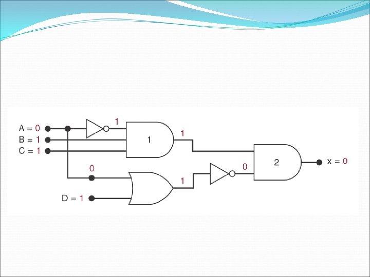
Evaluating Logic Circuit Output � Evaluation rule for Boolean expression 1) Perform all inversions of single terms 2) Perform all operations within parentheses 3) Perform an AND operation before an OR operation 4) If an expression has a bar over it, perform the expression first and then invert the result
Evaluating Logic-Circuit Outputs � x = ABC(A+D) � Determine the output x given A=0, B=1, C=1, D=1. � Can also determine output level from a diagram
Implementing Circuits from Boolean Expressions � y = AC+BC’+A’BC � x=(A+B)(B’+C)
y = AC+BC’+A’BC
x=(A+B)(B’+C)
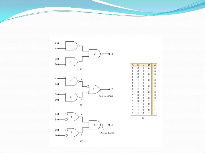
Alternate Logic Symbols � Sometimes the logic of a circuit is more easily understood if an alternative gate shape is used. � De. Morgan=s Theorem can be used to determine equivalent logic gates.
Alternate Logic Symbols �Rules: � 1. Change the gate shape (AND ==> OR; OR ==> AND). � 2. Change the bubbles (add where missing; remove if present).
Alternate Logic-Gate Representation