Logic Gates All very logical I think Logic


- Slides: 29
Logic Gates All very logical I think!
Logic Gates All very logical I think! So what are logic gates? A logic gate is an electronic switch
Logic Gates All very logical I think! So what are logic gates? A logic gate is an electronic switch Logic gates are found in everyday items such as washing machines, security lamps and video recorders.
Logic Gates All very logical I think! So what are logic gates? A logic gate is an electronic switch Logic gates are found in everyday items such as washing machines, security lamps and video recorders. Logic gates depend upon switches being on (1) or off (0)
Logic Gates A B Switch Gate
Logic Gates A B Switch Gate For the bulb in the circuit above to light up, both switches A and B need to be ON (closed). If either A or B is OFF (open) then the bulb will not work. A truth table gives us all possible combinations of the switches.
Logic Gates A B Switch Gate For the bulb in the circuit above to light up, both switches A and B need to be ON (closed). If either A or B is OFF (open) then the bulb will not work. A truth table gives us all possible combinations of the switches. Truth table Inputs Output A B Q 0 0 0 1 0 1 1 1 In the truth table: 0 = OFF 1 = ON
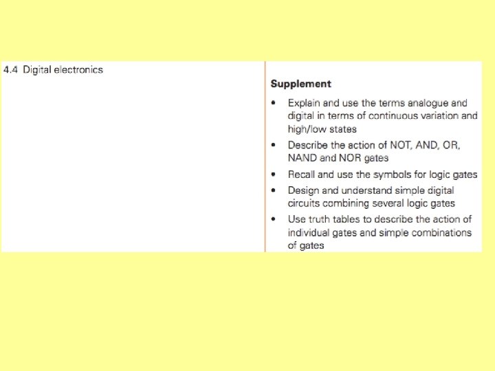
Just a minute – what’s all this analogue and digital stuff?
Just a minute – what’s all this analogue and digital stuff? A thermistor is an analogue device – it’s resistance varies over a continuous range.
Just a minute – what’s all this analogue and digital stuff? A stop clock, such as the one shown here, is a digital device because the strips that make up the display can only be on (1) of off (0)
A stop clock, such as the one shown here, is a digital device because the strips that make up the display can only be on (1) of off (0)
Logic gates
Logic gates AND gate Truth table Inputs Input A Input B AND Output Q Output A B Q 0 0 0 1 0 1 1 1 Two inputs, one output. For the output to be HIGH (on), both inputs must be HIGH.
Logic gates OR gate Truth table Inputs Input A Input B OR Output Q Output A B Q 0 0 0 1 0 1 1 1 Two inputs, one output. For the output to be HIGH (on), at least one of the inputs must be HIGH (can be both).
Logic gates NOT gate Truth table Input A NOT OR Output Q Input Output A Q 0 1 1 0 One input, one output. For the output to be HIGH (on), the input must be LOW (and vice versa)
Logic gates NAND gate Truth table Inputs Input A Input B NAND Output Q Two inputs, one output. For the output to be HIGH (on), both inputs A and B must NOT be HIGH. Output A B Q 1 1 0 1 0 1 1 0 0 1 This is equivalent to an AND gate with its output inverted by a NOT gate.
Logic gates NOR gate Truth table Inputs Input A Input B NOR Output Q Two inputs, one output. For the output to be HIGH (on), neither inputs A or B is HIGH. Output A B Q 1 1 0 0 0 1 This is equivalent to an OR gate with its output inverted by a NOT gate.
AND NOR NAND OR NOT
Simple circuits using Logic gates
Simple circuits using Logic gates Tape recorder Record button AND Recording circuits Play button The Play and the Record button have to be pressed simultaneously in order for the recording circuits to begin working.
Simple circuits using Logic gates Security light During the day the light sensor output is high. Light 1 sensor 0 0 Body heat sensor Relay 0 Lamp 0/1 During the day the body heat sensor can be either high or low – the AND gate will not be triggered. The relay controls a separate circuit with the lamp in it.
Simple circuits using Logic gates Security light When it is dark the light sensor output is low. Light 0 sensor 1 1 Body heat sensor Relay 1 1 When it is dark, if someone approaches the body heat sensor is triggered and becomes high The AND gate receives two high inputs and triggers the relay which causes the lamp to switch on. Lamp
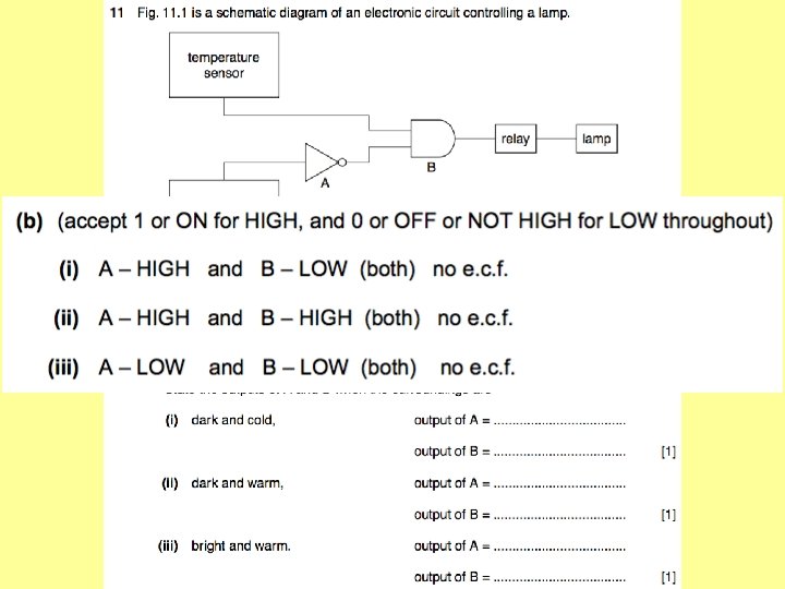
Simple circuits using Logic gates +5 V Test switch The alarm can be tested at any time by closing the test switch HIGH (1) A low temperature indicator – eg. In a greenhouse. When the greenhouse is warm enough, the input from the temperature sensor is HIGH (1). 0 V Temperature sensor 1 0 0 Alarm
Simple circuits using Logic gates +5 V Test switch The alarm can be tested at any time by closing the test switch HIGH (1) 0 V Temperature sensor 0 1 A low temperature indicator – eg. In a greenhouse. When the greenhouse cools, the input from the temperature sensor is LOW (0). The NOT gate changes this to a ‘ 1’ and the alarm is switched on. 1 Alarm
Simple circuits using Logic gates A night-time rain alarm. Light sensor Moisture sensor 1 0/1 0 During the day, the output from the light sensor is always HIGH (1) so the output from the NOT gate is always LOW (0) and the alarm is not switched on. 0 Alarm
Simple circuits using Logic gates A night-time rain alarm. Light sensor Moisture sensor 1 0 1 In darkness the output from the light sensor is LOW (0). This means that the output from the NOT switch is HIGH (1). If rain falls on the moisture sensor then its output becomes HIGH (1). The AND gate receives two HIGH inputs, so the alarm is switched on. 1 Alarm