
Location and Communication Systems for Safety Workers Dr
- Slides: 37
Location and Communication Systems for Safety Workers Dr. Neil Goldsman, Dr. Gilmer Blankenship and Dr. Carole Teolis Techno. Sciences Inc. TRX Systems
The Fire-Safe Locator System • Determines location of safety workers. • Communicates vital signs to base • Determines the presence of environmental factors hazardous to safety personnel • Operates both indoors and outside
Hardware Components of the Fire-Safe Locator • The Fire-Safe Locator System Components: – One central portable base station that is carried or worn by command firefighter or placed in truck. – Four substations placed at key locations at emergency site. – Personal transceivers that are worn by individual safety personnel.
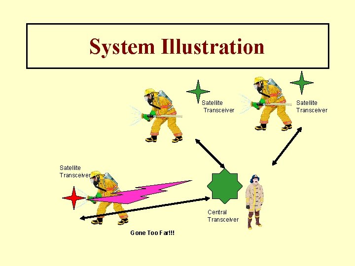
System Illustration Satellite Transceiver Central Transceiver Gone Too Far!!! Satellite Transceiver
What the Fire-Safe Locator Does Demonstrate by Example: Fire alarm rings. Commander takes personal transceivers and the central unit to emergency site. • Each firefighter wears a personal transceiver that transmits a unique code. • The central unit knows which firefighter has which code. • The central unit communicates with each firefighter sequentially. • During the communication sequence, the location, the vital signs, and any environmental hazard are transmitted to the base station. • An alarm sounds if a safety worker is in trouble.
How it Works: Technical Summary • Each transceiver and central unit are designed using state-of-the-art CMOS electronics • Each transceiver and the central unit is preprogrammed with a unique code. • Each transceiver in the system is numbered. • The user (fire-chief, etc. ) tells the central unit the name of the firefighter that has each transceiver. (Each firefighter is associated with a specific transceiver. )
How it Works: Technical Summary • Using a digital modulation scheme, the central unit and the transceiver communicate with each other at regular intervals. (Approximately once a second. ) • Using a set of state-of-the art location algorithms involving hardware and software, the central unit determines the location of the personal transceiver and hence the firefighter. • We have designated our state-of-the-art location algorithms as ‘Integrated Positioning’
How Integrated Positioning Works: Integrated Positioning combines five different technologies: 1. Global Positioning System (GPS) 2. Accelerometers and Numerical Integration 3. Active Radar 4. Received Signal Strength Indication (RSSI) 5. Orthogonal Signal Phase Delay Positioning (OSPDP)
How Integrated Positioning Works: Technology I: GPS • Each personal transceiver, base station and substation will be equipped with a GPS receiver. • The GPS location of each personal transmitter will be transmitted to the base and substations. • Upon going indoors the GPS operation will likely terminate. • The final location and time before GPS terminates will be recorded by the network providing a coordinate origin for the particular safety worker.
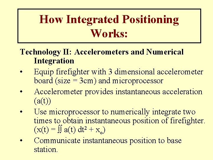
How Integrated Positioning Works: Technology II: Accelerometers and Numerical Integration • Equip firefighter with 3 dimensional accelerometer board (size = 3 cm) and microprocessor • Accelerometer provides instantaneous acceleration (a(t)) • Use microprocessor to numerically integrate two times to obtain instantaneous position of firefighter. (x(t) = ∫∫ a(t) dt 2 + xo) • Communicate instantaneous position to base station.
How Integrated Positioning Works: Technology III: Active Radar • Determines distance using GHz clocks, RF pulses and the speed of light. • Substation sends RF pulse and starts GHz clock (super high speed) at same time. • Firefighter’s transceiver receives and returns RF pulse to substation. • Substation receives back RF pulse and stops its clock. • Distance from Firefighter to substation calculated Distance = (speed of light) x (elapsed clock time) • Elapsed clock time is on order of nanoseconds realized by high speed CMOS electronics • Use 3 substations to triangulate and get precise coordinates
How Integrated Positioning Works: Technology IV: Received Signal Strength Indicator (RSSI) • The base station, substations and personal transceivers will all be equipped with an RSSI circuit that indicates the power of the signal that the firefighter is transmitting to the base station, substations (and other figherfighters). • From the signal strength we will obtain information as to how far away a specific firefighter is from a base or substation. • To aid in this process, local RSSI’s can be placed at known locations indoors at emergency site to monitor signal strengths’ of safety workers as well. • RSSI information will then be transmitted to base station.
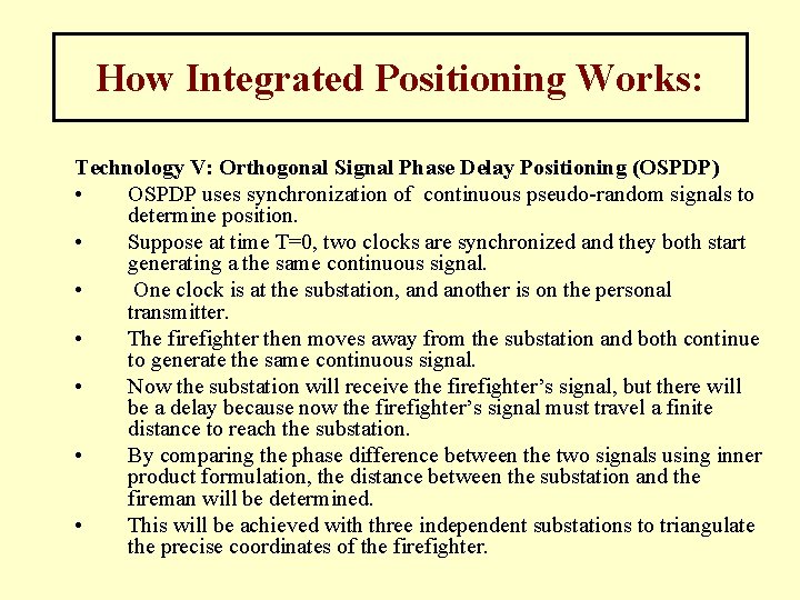
How Integrated Positioning Works: Technology V: Orthogonal Signal Phase Delay Positioning (OSPDP) • OSPDP uses synchronization of continuous pseudo-random signals to determine position. • Suppose at time T=0, two clocks are synchronized and they both start generating a the same continuous signal. • One clock is at the substation, and another is on the personal transmitter. • The firefighter then moves away from the substation and both continue to generate the same continuous signal. • Now the substation will receive the firefighter’s signal, but there will be a delay because now the firefighter’s signal must travel a finite distance to reach the substation. • By comparing the phase difference between the two signals using inner product formulation, the distance between the substation and the fireman will be determined. • This will be achieved with three independent substations to triangulate the precise coordinates of the firefighter.
Computer Modeling of Radio Frequency (RF) Indoor Location Signals
Computer Modeling of Indoor RF Signals • • Much of indoor location is based on propagation of radio frequency (RF) electromagnetic waves. We have developed a unique algorithm for emulating the propagation of indoor RF. This capability provides a unique advantage to our Integrated Positioning Technology The method has been published in academic journals and received enthusiastic response. The technique is called the Finite Difference Time Domain Alternating Direction Implicit Method for Solving Maxwell’s Equations (FDTD-ADI). Maxwell’s Equations are a complicated set of partial differential vector equations that describe RF waves. The following slides show results of these calculations indicating how RF waves propagate inside buildings.
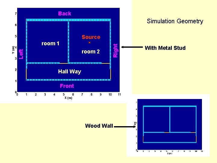
Back Simulation Geometry room 1 Left room 2 Right Source Hall Way Front Wood Wall With Metal Stud
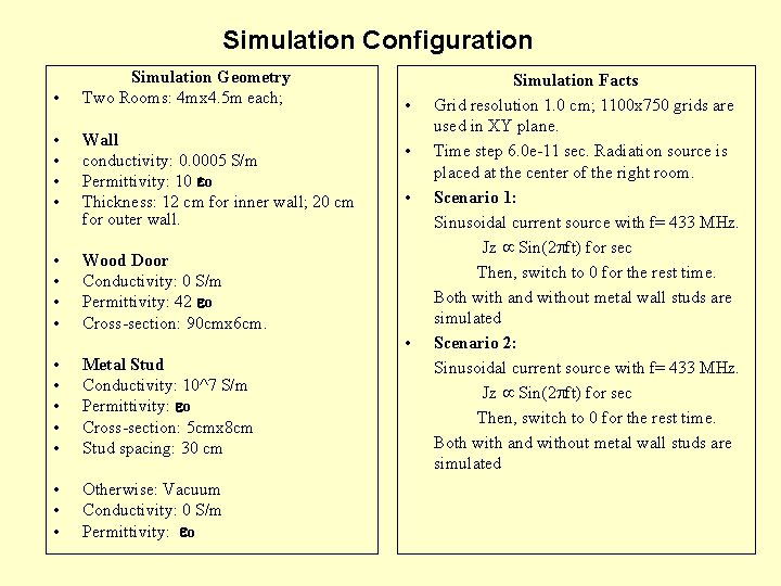
Simulation Configuration • Simulation Geometry Two Rooms: 4 mx 4. 5 m each; • • Wall conductivity: 0. 0005 S/m Permittivity: 10 o Thickness: 12 cm for inner wall; 20 cm for outer wall. • • Wood Door Conductivity: 0 S/m Permittivity: 42 o Cross-section: 90 cmx 6 cm. • • • Metal Stud Conductivity: 10^7 S/m Permittivity: o Cross-section: 5 cmx 8 cm Stud spacing: 30 cm • • • Otherwise: Vacuum Conductivity: 0 S/m Permittivity: o Simulation Facts Grid resolution 1. 0 cm; 1100 x 750 grids are used in XY plane. Time step 6. 0 e-11 sec. Radiation source is placed at the center of the right room. Scenario 1: Sinusoidal current source with f= 433 MHz. Jz Sin(2 ft) for sec Then, switch to 0 for the rest time. Both with and without metal wall studs are simulated Scenario 2: Sinusoidal current source with f= 433 MHz. Jz Sin(2 ft) for sec Then, switch to 0 for the rest time. Both with and without metal wall studs are simulated
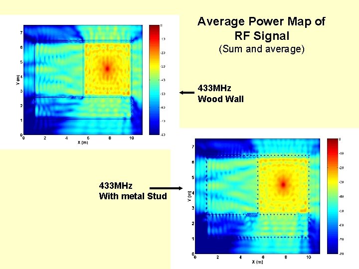
Average Power Map of RF Signal (Sum and average) 433 MHz Wood Wall 433 MHz With metal Stud
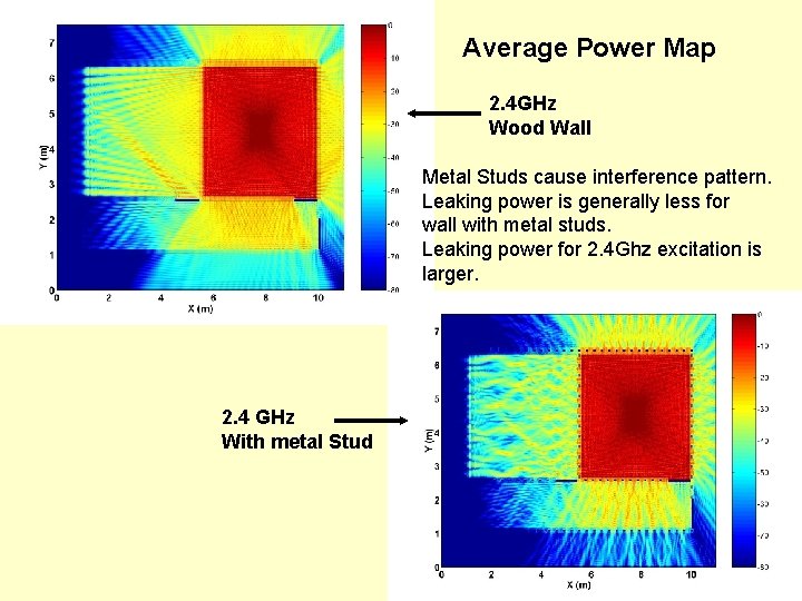
Average Power Map 2. 4 GHz Wood Wall Metal Studs cause interference pattern. Leaking power is generally less for wall with metal studs. Leaking power for 2. 4 Ghz excitation is larger. 2. 4 GHz With metal Stud
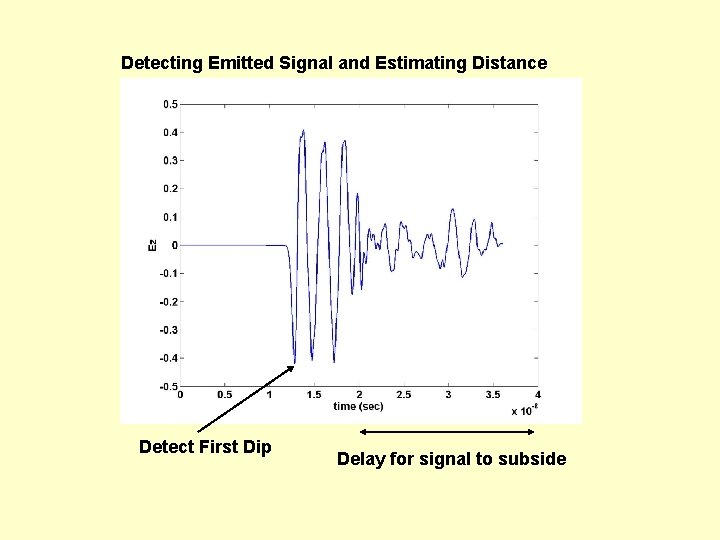
Detecting Emitted Signal and Estimating Distance Detect First Dip Delay for signal to subside
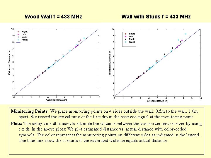
Wood Wall f = 433 MHz Wall with Studs f = 433 MHz Monitoring Points: We place monitoring points on 4 sides outside the wall: 0. 5 m to the wall, 1. 0 m apart. We record the arrival time of the first dip in the received signal at the monitoring point. Plots: The delay time dt is used to estimate the distance between the transmitter and receiver by using c x dt. In the above plots: We plot estimated distance vs. actual distance with color-coded symbols. The color represents the monitoring points on different sides as indicated in the legend. The blue line show the scenario if the estimated distance equals actual distance.
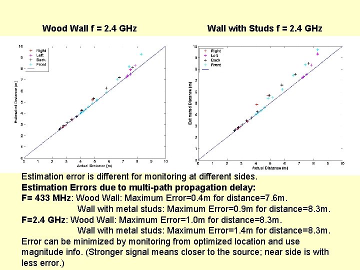
Wood Wall f = 2. 4 GHz Wall with Studs f = 2. 4 GHz Estimation error is different for monitoring at different sides. Estimation Errors due to multi-path propagation delay: F= 433 MHz: Wood Wall: Maximum Error=0. 4 m for distance=7. 6 m. Wall with metal studs: Maximum Error=0. 9 m for distance=8. 3 m. F=2. 4 GHz: Wood Wall: Maximum Error=1. 0 m for distance=8. 3 m. Wall with metal studs: Maximum Error=1. 4 m for distance=8. 3 m. Error can be minimized by monitoring from optimized location and use magnitude info. (Stronger signal means closer to the source; near side is with less error. )
Active Radar Some Technology Details
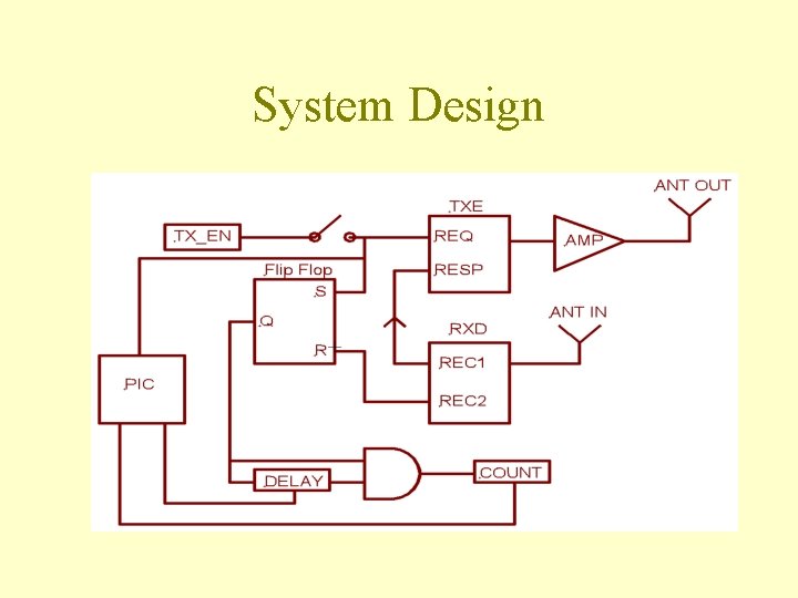
Active Radar Summary • System Design – Transmission – Timing • • • Components Transmission Theory Timing Theory Circuit Design Current Status
System Design
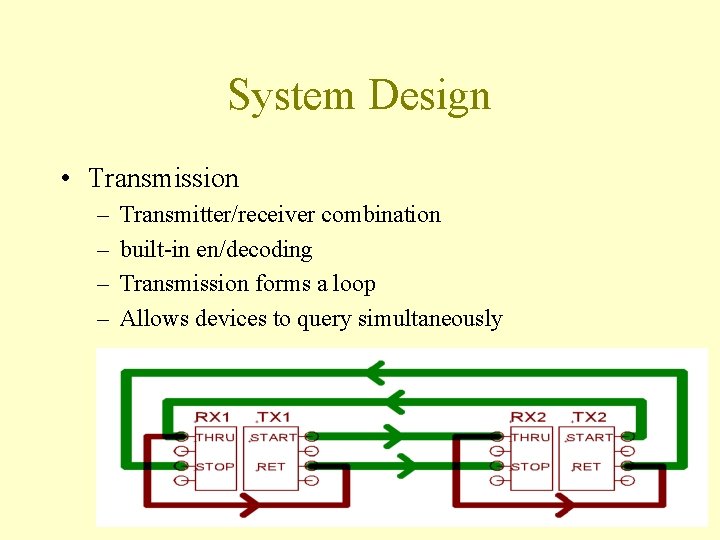
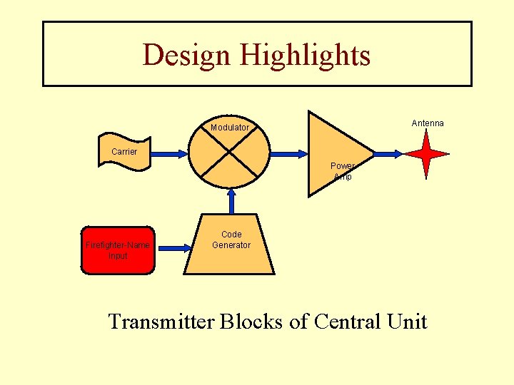
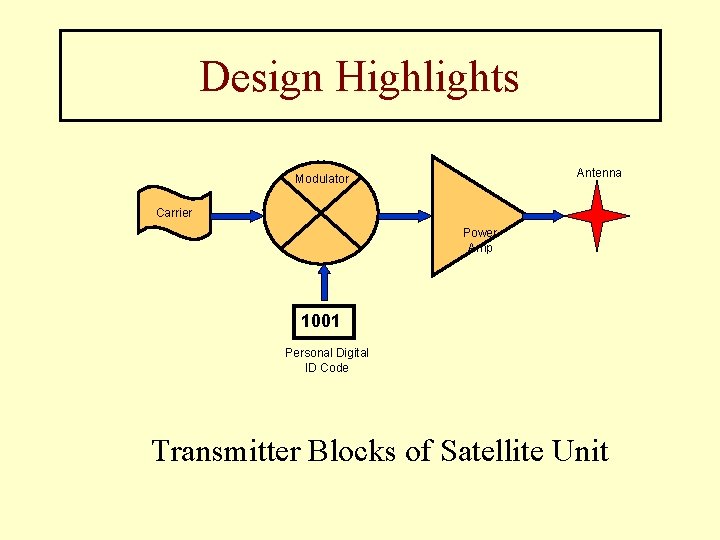
System Design • Transmission – – Transmitter/receiver combination built-in en/decoding Transmission forms a loop Allows devices to query simultaneously
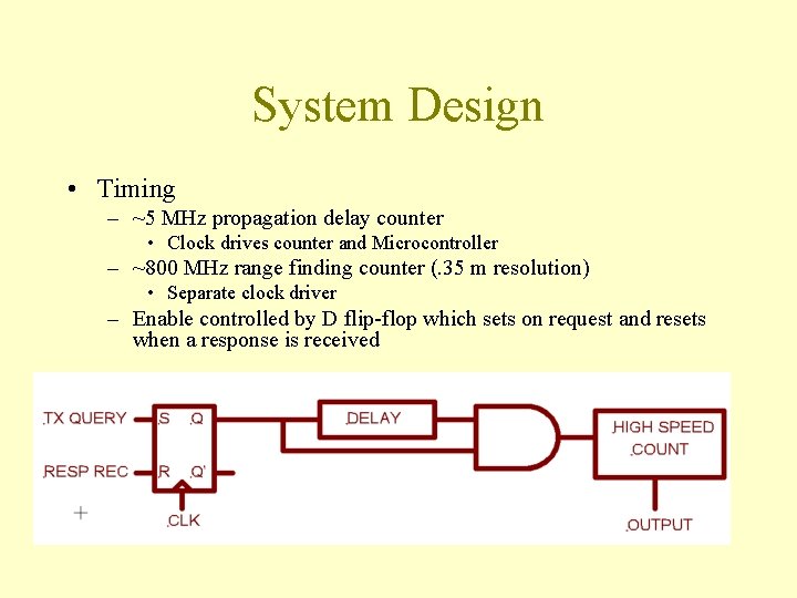
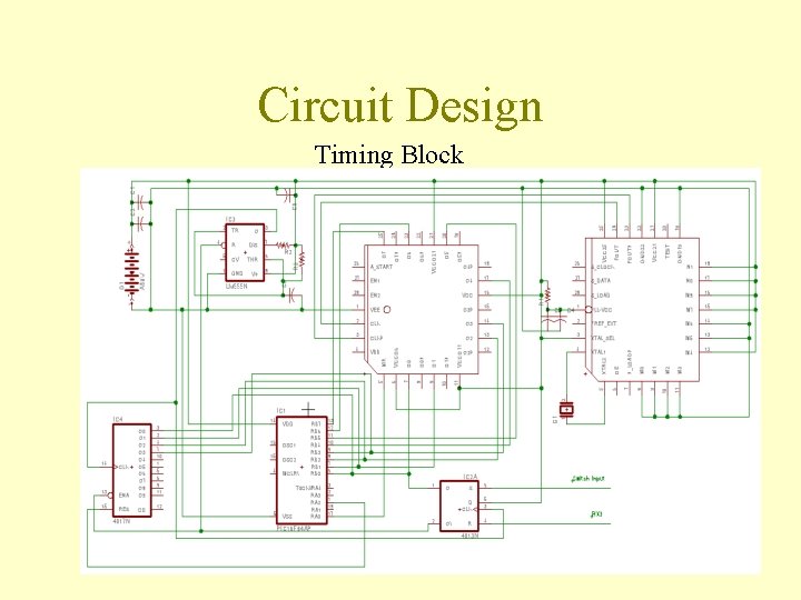
System Design • Timing – ~5 MHz propagation delay counter • Clock drives counter and Microcontroller – ~800 MHz range finding counter (. 35 m resolution) • Separate clock driver – Enable controlled by D flip-flop which sets on request and resets when a response is received
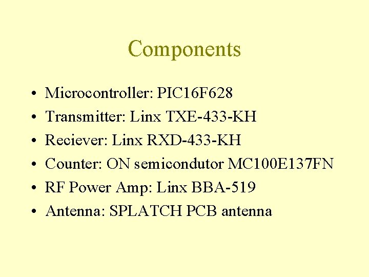
Components • • • Microcontroller: PIC 16 F 628 Transmitter: Linx TXE-433 -KH Reciever: Linx RXD-433 -KH Counter: ON semicondutor MC 100 E 137 FN RF Power Amp: Linx BBA-519 Antenna: SPLATCH PCB antenna
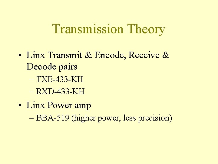
Transmission Theory • Linx Transmit & Encode, Receive & Decode pairs – TXE-433 -KH – RXD-433 -KH • Linx Power amp – BBA-519 (higher power, less precision)
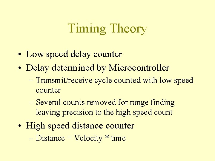
Timing Theory • Low speed delay counter • Delay determined by Microcontroller – Transmit/receive cycle counted with low speed counter – Several counts removed for range finding leaving precision to the high speed count • High speed distance counter – Distance = Velocity * time
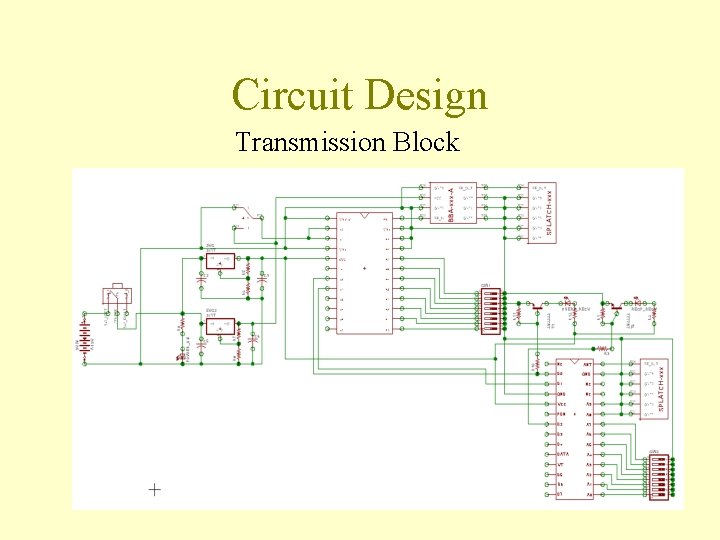
Circuit Design Transmission Block
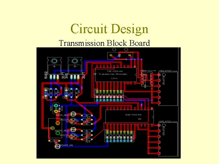
Circuit Design Transmission Block Board
Circuit Design Timing Block
Current Status • • Transmission board is complete Timing schematic needs revision High speed counters need to be ordered Microcontroller delay and operation code
Design Highlights Antenna Modulator Carrier Power Amp Firefighter-Name Input Code Generator Transmitter Blocks of Central Unit
Design Highlights Antenna Modulator Carrier Power Amp 1001 Personal Digital ID Code Transmitter Blocks of Satellite Unit
Integrated Positioning Summary 1. 2. 3. 4. 5. We are developing a system for indoor and outdoor position detection by integrating five different technologies Each technology will independently provide values for the specific location of a safety worker These independent values will be transmitted to the central base station. Using a voting algorithm that we are developing, the central base station will use the data from the five independent technologies to decide the most likely location of the safety personnel. Vital signs and environmental factors will also be transmitted to base station. An alarm will sound if the safety worker is experiencing too high a danger factor.