Local Head Losses Local head losses are the


 • Then the pressure")


- Slides: 41
Local Head Losses ØLocal head losses are the “loss” of energy at point where the pipe changes dimension (and/or direction). • Pipe Expansion • Pipe Contraction • Entry to a pipe from a reservoir • Exit from a pipe to a reservoir • Valve (may change with time) • Orifice plate • Tight bends Ø They are “velocity head losses” and are represented by
Value of k. L • For junctions and bends we need experimental measurements • k. L may be calculated analytically for Ø Expansion Ø Contraction • By considering continuity and momentum exchange and Bernoulli
Losses at an Expansion • As the velocity reduces (continuity) • Then the pressure must increase (Bernoulli) • So turbulence is induced and head losses occur Turbulence and losses
Value of k. L for Expansion 1 2 • Apply the momentum equation from 1 to 2 • Using the continuity equation we can eliminate Q • From Bernoulli
Value of k. L for Expansion • Combine and - Borda-Carnot Equation • Using the continuity equation again
Losses at Contraction • Flow converges as the pipe contracts • Convergence is narrower than the pipe Ø Due to vena contractor • Experiments show for common pipes • Can ignore losses between 1 and 1’ Ø As Convergent flow is very stable
Losses at Contraction • Apply the general local head loss equation between 1’ and 2 • And Continuity The value of k depends on In general
Losses: Junctions
Losses: Sharp bends
k. L values Bell mouth Entry T-branch k. L= 1. 5 k. L= 0. 1 Bellmouth entry Sharp exit 90 o Bend 90 o Tees flow in line to line Branch Gate value (open) k. L Values 0. 1 0. 5 0. 4 1. 5 0. 25 k. L= 0. 5 Sharp Entry/Exit T-inline k. L= 0. 4
Pipeline Analysis • Bernoulli Equation Ø equal to a constant: Total Head, H • Applied from one point to another (A to B) Ø With head losses
Bernoulli Graphically • Reservoir • Pipe of Constant diameter • No Flow A
Bernoulli Graphically • Constant Flow • Constant Velocity • No Friction A
Bernoulli Graphically • Constant Flow • Constant Velocity • No Friction A Change of Pipe Diameter
Bernoulli Graphically • Constant Flow • Constant Velocity • With Friction A
Reservoir Feeding Pipe Example 5. 0 m
Reservoir Feeding Pipe Example • Apply Bernoulli with head losses p. A=p. C = Atmospheric u. A = negligible
• Find pressure at B: Apply Bernoulli A-B p. A= Atmospheric u = u. B = 2. 41 m/s Negative i. e. less than Atmospheric pressure
Pipes in series • Consider the situation when the pipes joining two reservoirs are connected in series 1 2 • Total loss of head for the system is given as Q 1 = Q 2 = Qn = Q A 1 U 1 = A 2 U 2 = A n Un = Q
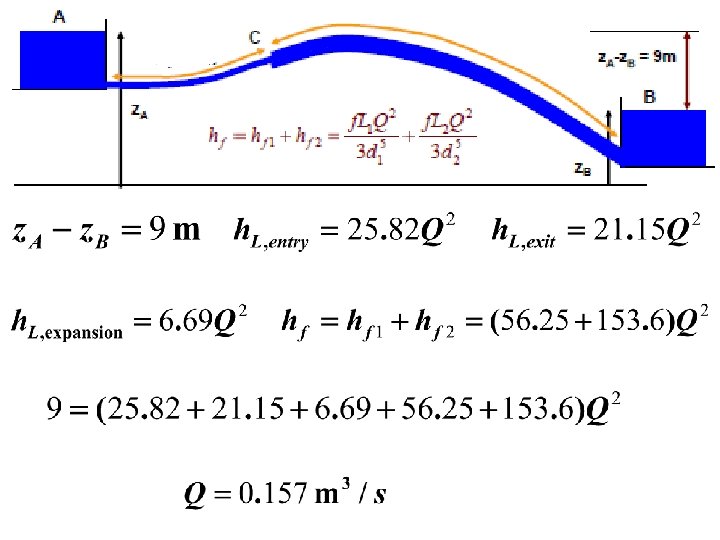
Pipes in Series Example • Two reservoirs, height difference 9 m, joined by a pipe that changes diameter. For, 15 m d=0. 2 m then for 45 m, d=0. 25 m. f = 0. 01 for both lengths. • Use k. L, entry= 0. 5, k. L, exit = 1. 0. Treat the joining of the pipes as a sudden expansion. • Find the flow between the reservoirs.
• Apply Bernoulli A-B
Pipes in parallel • The head loss across the pipes is equal • Diameter, f, length L, Q, andu may differ • Total flow is sum in each pipe
1. Knowing the loss of head, the discharges in each pipe can be obtained • The values of U 1, U 2 and U 3 may be obtained from the above equations and hence the discharges Q 1, Q 2 and Q 3 obtained.
2. The discharge Q is given, the distribution of discharge in different branches is required • The discharges Q 1, Q 2, Q 3 can be expressed in terms of H Where
Similarly Therefore: As the discharge is known and K 1, K 2 and K 3 are constants, the value of H is obtained and the discharge in individual pipes obtained
Pipes in Parallel Example • Two pipes connect two reservoirs which have a height difference of 10 m. Pipe 1 has diameter 50 mm and length 100 m. Pipe 2 has diameter 100 mm and length 100 m. Both have entry loss k. L, entry = 0. 5 and exit loss k. L, exit =1. 0 and Darcy f of 0. 008. • Find Q in each pipe • Diameter D of a pipe 100 m long and same f that could replace the two pipes and provide the same flow.
Apply Bernoulli for each pipe separately Pipe 1:
Pipe 2:
• Flow required in new pipe = • Replace u using continuity Must solve iteratively
• Must solve iteratively for D • Get approximate answer by leaving the 2 nd term • Increase deq a little, say to 0. 106 • … a little more … to 0. 107 So
Flow through a by-pass • A by-pass is a small diameter pipe connected in parallel to the main pipe Meter By-pass Main pipe The ratio of q in the by-pass, to the total discharge is known as the by-pass coefficient
• Head loss in main pipe = head loss in by-pass Minor losses in the by-pass due to bend and the meter etc Divide by Implies
Using continuity equation Adding one on both sides
By-pass coefficient • Knowing the by-pass coefficient, the total discharge in the main pipe can be determined