
LMQXF Bus and Expansion Loop Status R Bossert
LMQXF Bus and Expansion Loop Status R. Bossert Nov. 1, 2017

Conceptual design of expansion loops and bus configuration was completed and is shown below. Since the bus port is not placed symmetrically with respect to the cold mass, there will be two different bus loop configurations on the face of the cold mass. Q 1 a/Q 3 a Q 1 b/Q 3 b Instrumentation port position d Lea s ds Lea CLIQ Bus port CLIQ Bus port R. Bossert Nov. 1, 2017 2
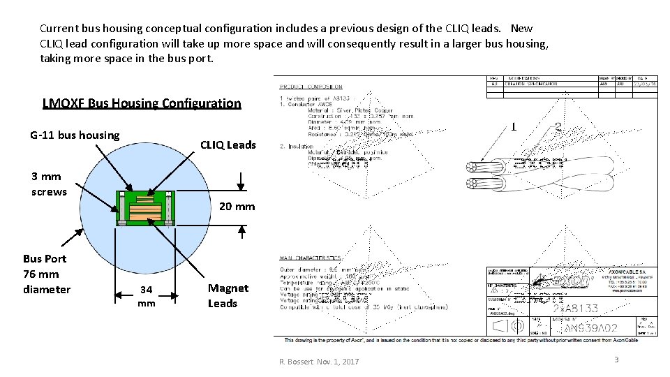
Current bus housing conceptual configuration includes a previous design of the CLIQ leads. New CLIQ lead configuration will take up more space and will consequently result in a larger bus housing, taking more space in the bus port. LMQXF Bus Housing Configuration G-11 bus housing CLIQ Leads 3 mm screws Bus Port 76 mm diameter 20 mm 34 mm Magnet Leads R. Bossert Nov. 1, 2017 3
Assembly of a mockup, which will include both bus loop configurations and a through-bus, is beginning. • • Space has been allocated in Industrial Building 3, and a dedicated technician has been assigned. Models have been obtained (from Mike Solis) of all the magnet end and splice connection box assemblies. Cable for power leads has been obtained. Drawings of connection box and end plate assemblies for mockup have been completed. Still need to: • • • Receive mockup parts. Obtain end dome model and add this to the mockup. Order through-bus port for mockup. Design through bus after confirmation of CLIQ lead configuration. Obtain CLIQ leads for mockup. Build mockup. Form power leads and CLIQ leads Insert through bus port on mockup and short model. Assess results R. Bossert Nov. 1, 2017 4
LMQXF Splice and Bus Mockup Schedule R. Bossert Nov. 1, 2017 5
- Slides: 5