
LITAR ELEKTRIK II EET 1024 SILIBUS LITAR ELEKTRIK
LITAR ELEKTRIK II EET 102/4
SILIBUS LITAR ELEKTRIK II Mutual Inductance Ø Two port Network n Pengenalan Jelmaan Laplace n Kaedah Jelmaan Laplace Dlm Analisis Litar n Sambutan Frekuensi Litar AC n Siri Fourier n Jelmaan Fourier Ø
MUTUAL INDUCTANCE Self inductance n Concept of mutual inductance n Dot convention n Energy in a coupled circuit n Linear transformer n Ideal transformer n
MUTUAL INDUCTANCE INTRODUCTION n magnetically coupled n When two loops with or without contacts between them, affect each other through magnetic field generated by one of them – they are said to be magnetically coupled. n Example of device using this concepttransformer.
Transformer Use magnetically coupled coils to transfer energy from one circuit to another. n Key circuit element where it is used for stepping down or up ac voltages or currents. n Also used in electronic circuits such as radio and tv receiver. n
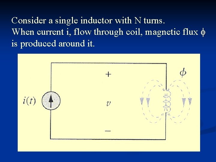
Consider a single inductor with N turns. When current i, flow through coil, magnetic flux is produced around it.
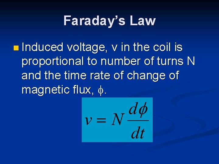
Faraday’s Law n Induced voltage, v in the coil is proportional to number of turns N and the time rate of change of magnetic flux, .
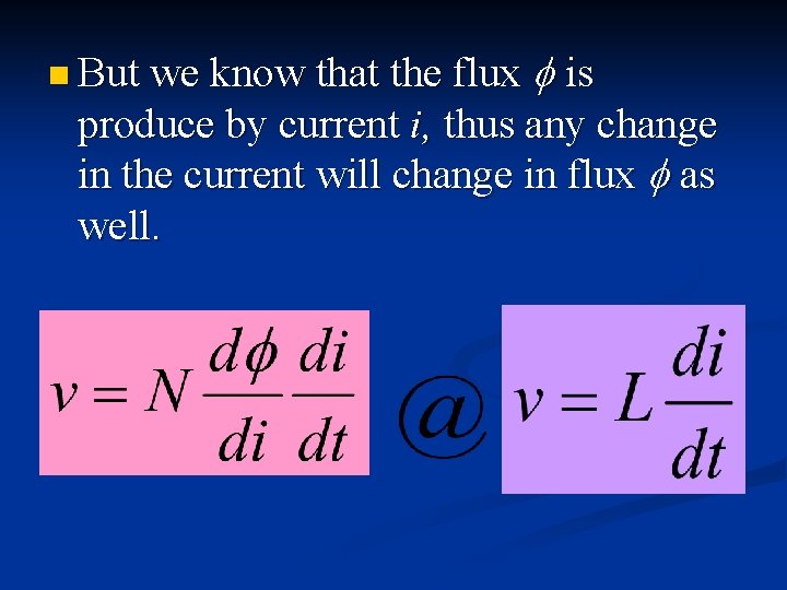
n But we know that the flux is produce by current i, thus any change in the current will change in flux as well.
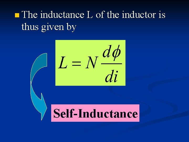
n The inductance L of the inductor is thus given by Self-Inductance
Self Inductance n Inductance that relates the induced voltage in a coil with a time-varying current in the same coil.
Mutual Inductance n When two inductors or coils are in close proximity to each other, magnetic flux caused by current in one coil links with the other coil, therefore producing the induced voltage.
Mutual Inductance
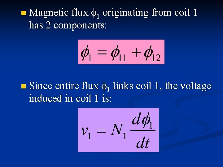
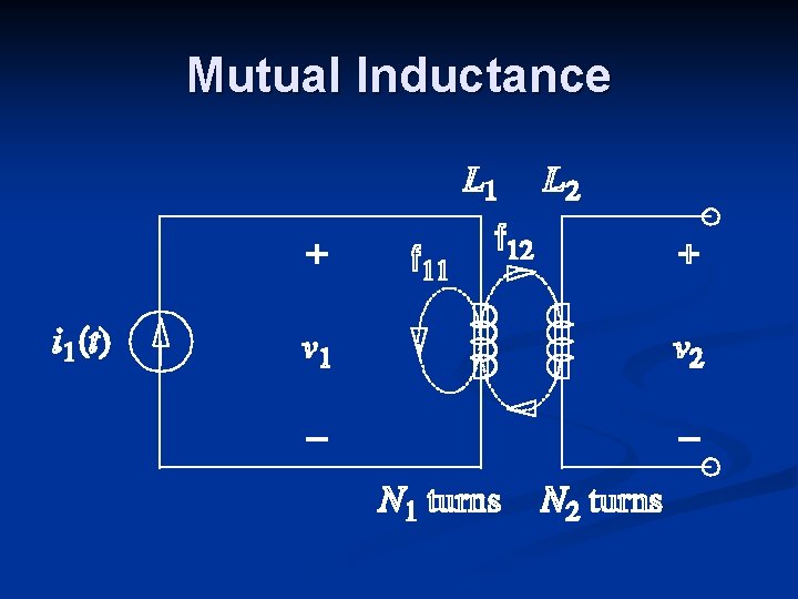
n n Magnetic flux 1 originating from coil 1 has 2 components: Since entire flux 1 links coil 1, the voltage induced in coil 1 is:
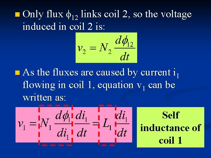
n Only flux 12 links coil 2, so the voltage induced in coil 2 is: n As the fluxes are caused by current i 1 flowing in coil 1, equation v 1 can be written as: Self inductance of coil 1
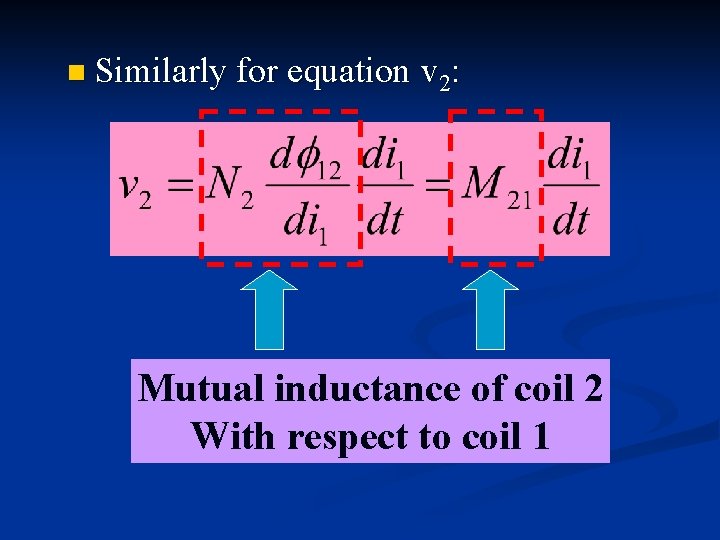
n Similarly for equation v 2: Mutual inductance of coil 2 With respect to coil 1
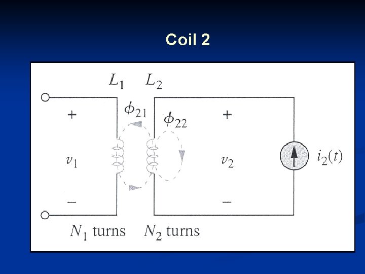
Coil 2
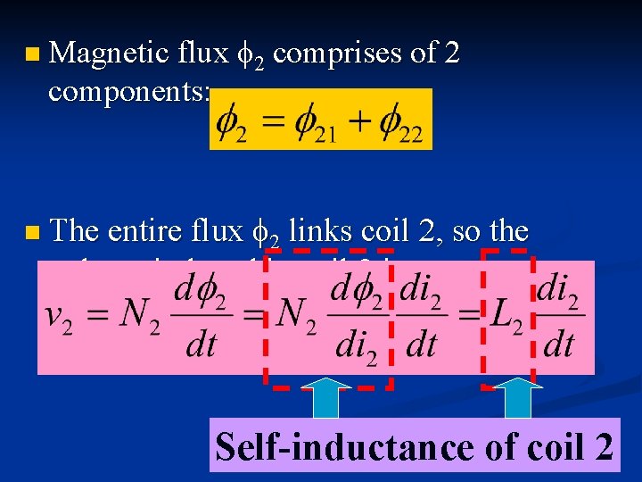
n Magnetic flux components: 2 comprises of 2 2 links coil 2, so the voltage induced in coil 2 is: n The entire flux Self-inductance of coil 2
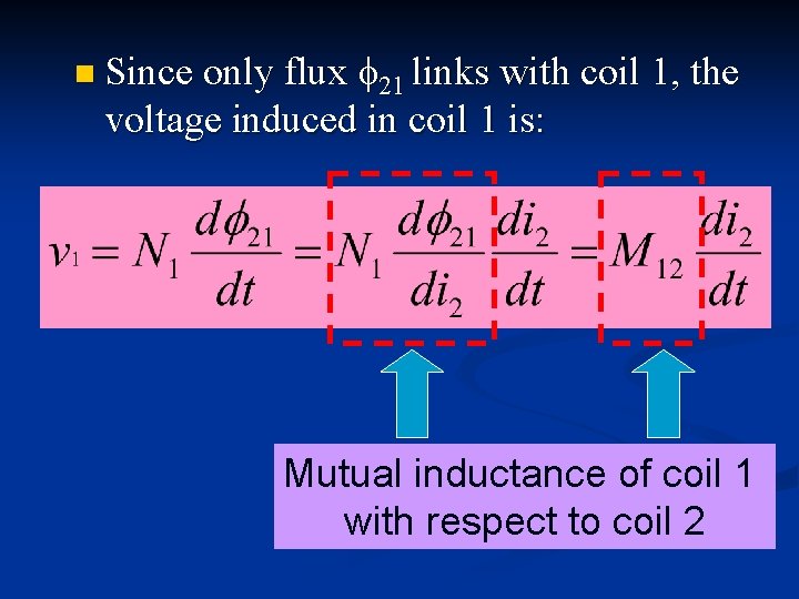
n Since only flux 21 links with coil 1, the voltage induced in coil 1 is: Mutual inductance of coil 1 with respect to coil 2
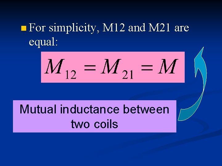
n For simplicity, M 12 and M 21 are equal: Mutual inductance between two coils
Reminder Mutual coupling exists when inductors or coils are in close proximity and circuit are driven by time-varying sources. n Mutual inductance is the ability of one inductor to induce voltage across a neighboring inductor, measured in henrys (H). n
Dot Convention n. A dot is placed in the circuit at one end of each of the two magnetically coupled coils to indicate the direction of magnetic flux if current enters that dotted terminal of the coil.
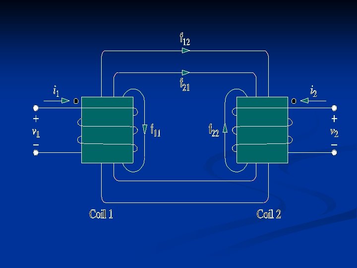
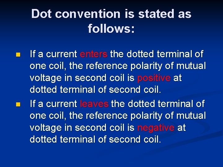
Dot convention is stated as follows: n n If a current enters the dotted terminal of one coil, the reference polarity of mutual voltage in second coil is positive at dotted terminal of second coil. If a current leaves the dotted terminal of one coil, the reference polarity of mutual voltage in second coil is negative at dotted terminal of second coil.
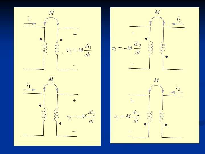
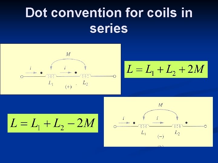
Dot convention for coils in series
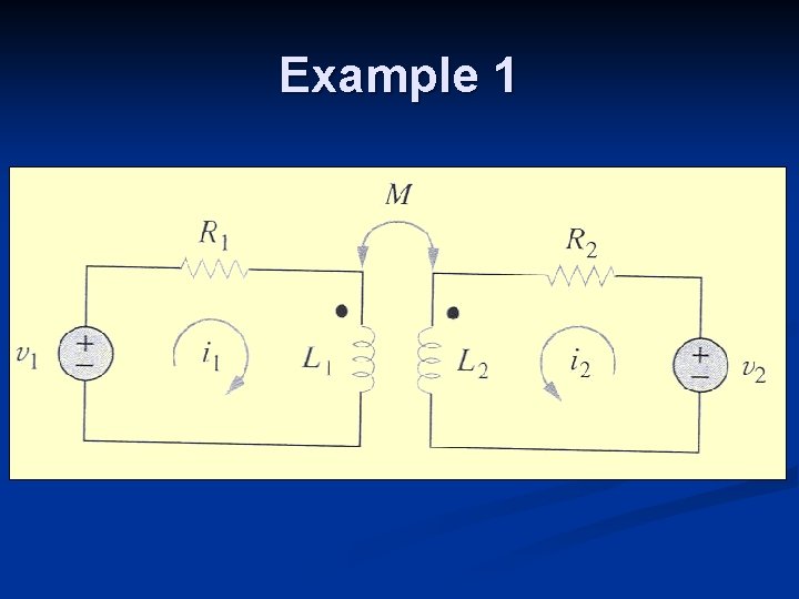
Example 1
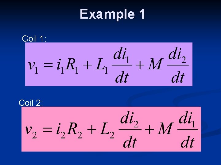
Example 1 Coil 1: Coil 2:
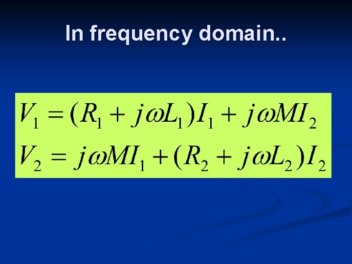
In frequency domain. .
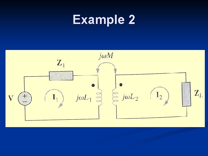
Example 2
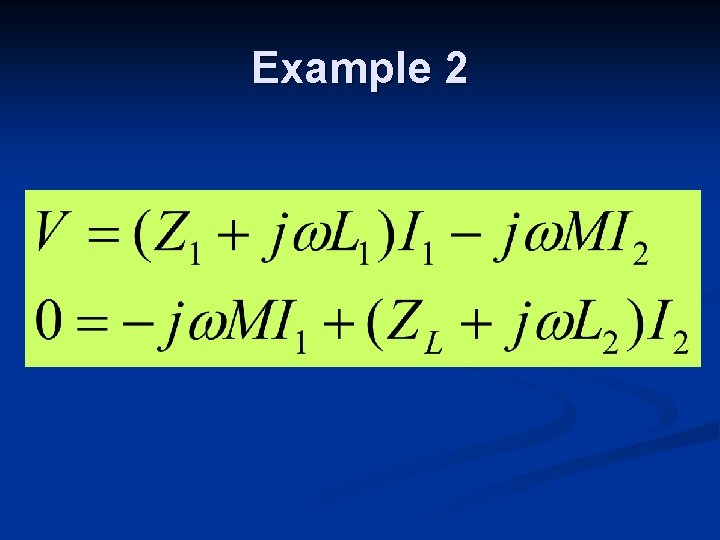
Example 2
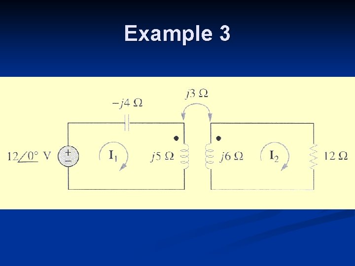
Example 3
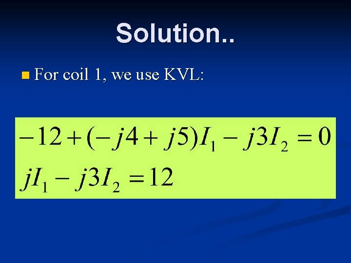
Solution. . n For coil 1, we use KVL:
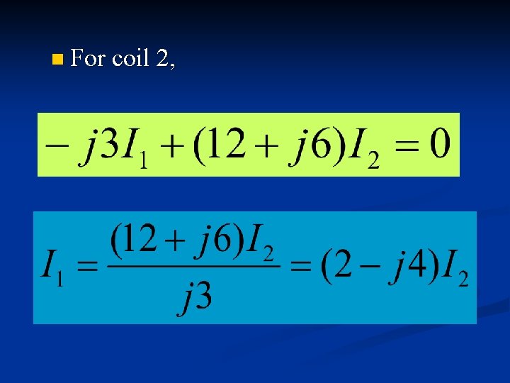
n For coil 2,
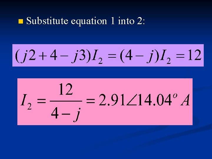
n Substitute equation 1 into 2:
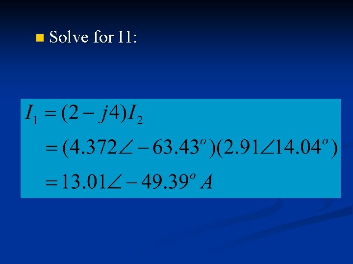
n Solve for I 1:
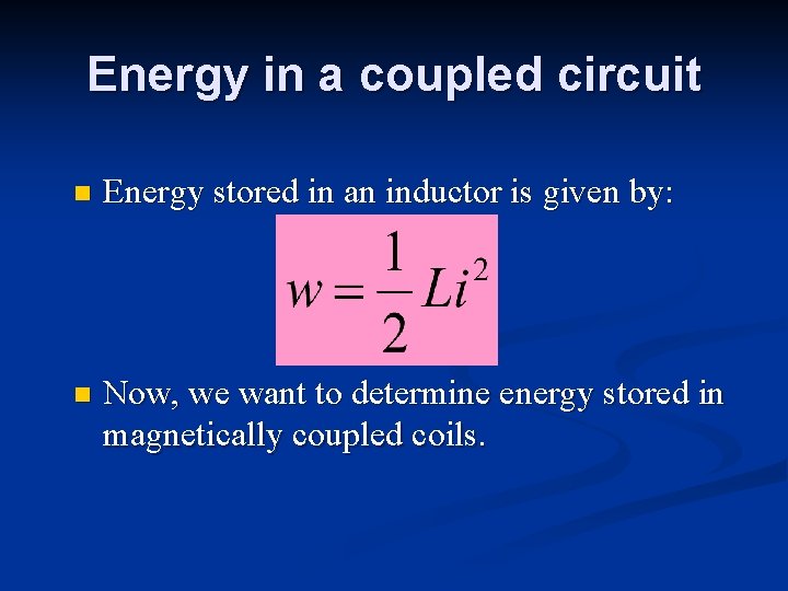
Energy in a coupled circuit n Energy stored in an inductor is given by: n Now, we want to determine energy stored in magnetically coupled coils.
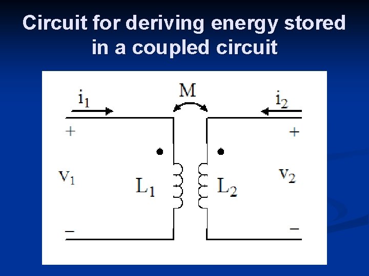
Circuit for deriving energy stored in a coupled circuit
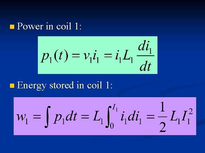
n Power in coil 1: n Energy stored in coil 1:
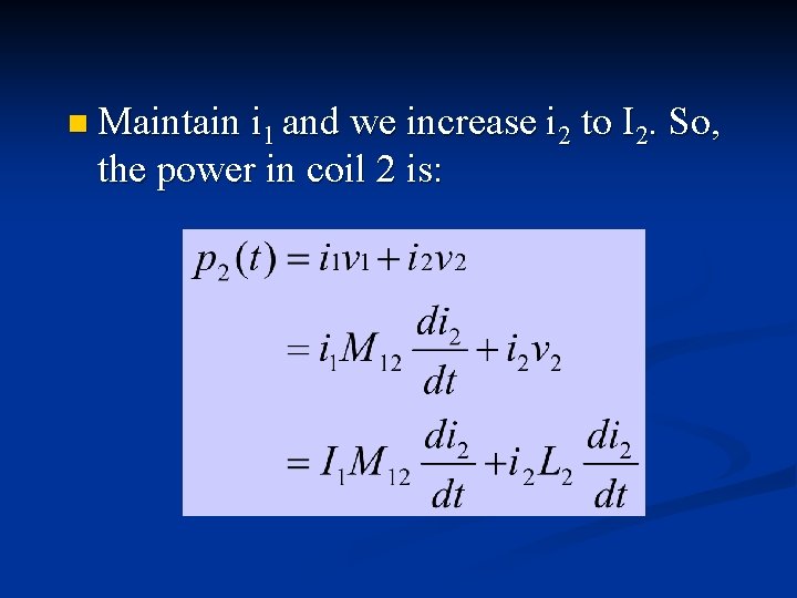
n Maintain i 1 and we increase i 2 the power in coil 2 is: to I 2. So,
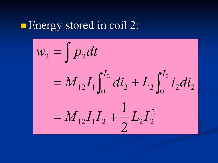
n Energy stored in coil 2:
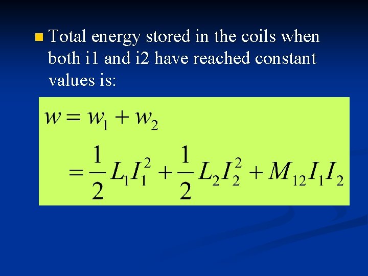
n Total energy stored in the coils when both i 1 and i 2 have reached constant values is:
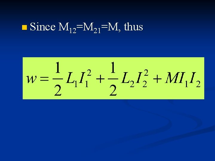
n Since M 12=M 21=M, thus
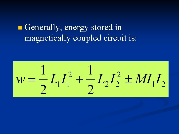
n Generally, energy stored in magnetically coupled circuit is:
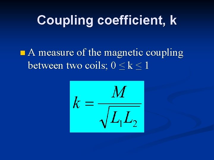
Coupling coefficient, k n A measure of the magnetic coupling between two coils; 0 ≤ k ≤ 1
Linear Transformer is generally a four-terminal device comprising two or more magnetically coupled coils. n Coil that is directly connected to voltage source is primary winding. n Coil connected to the load is called secondary winding. n R 1 and R 2 included to calculate for losses in coils. n
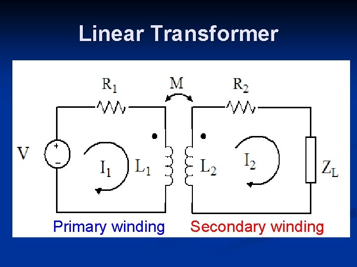
Linear Transformer Primary winding Secondary winding
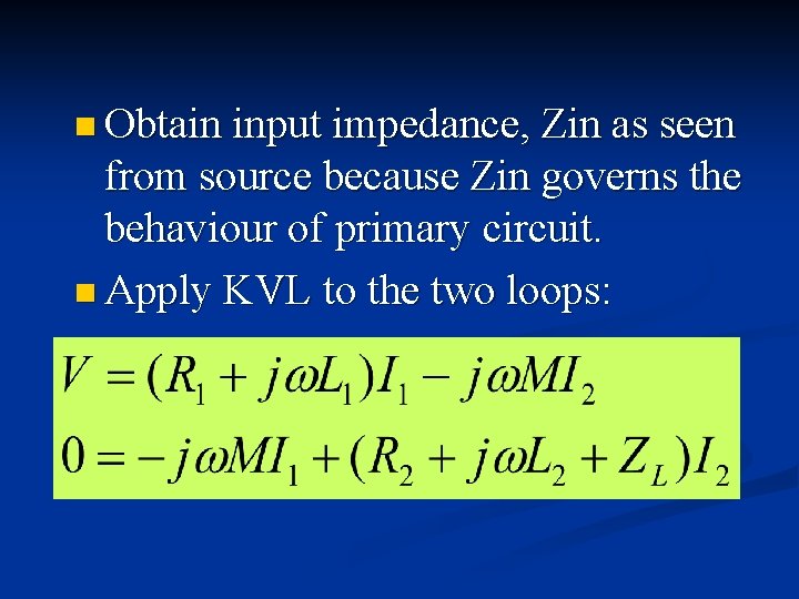
n Obtain input impedance, Zin as seen from source because Zin governs the behaviour of primary circuit. n Apply KVL to the two loops:
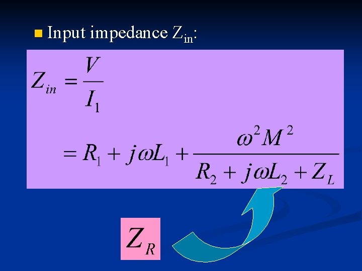
n Input impedance Zin:
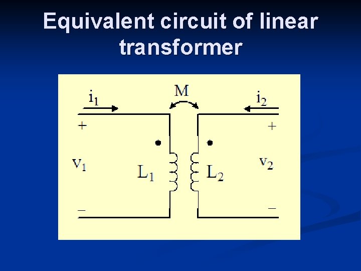
Equivalent circuit of linear transformer
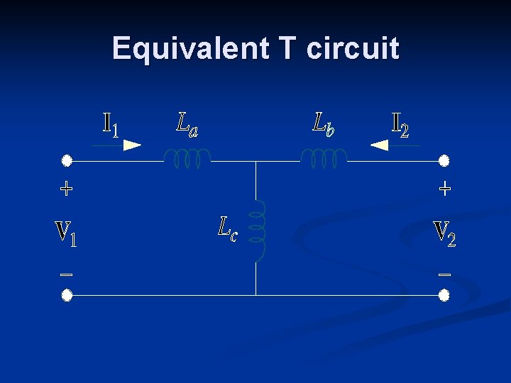
Equivalent T circuit
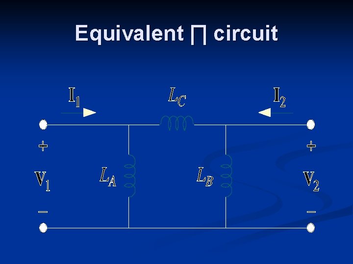
Equivalent ∏ circuit
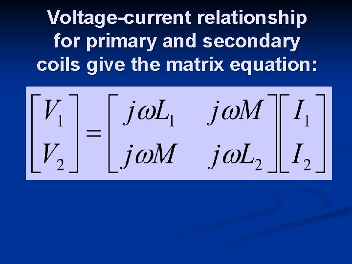
Voltage-current relationship for primary and secondary coils give the matrix equation:
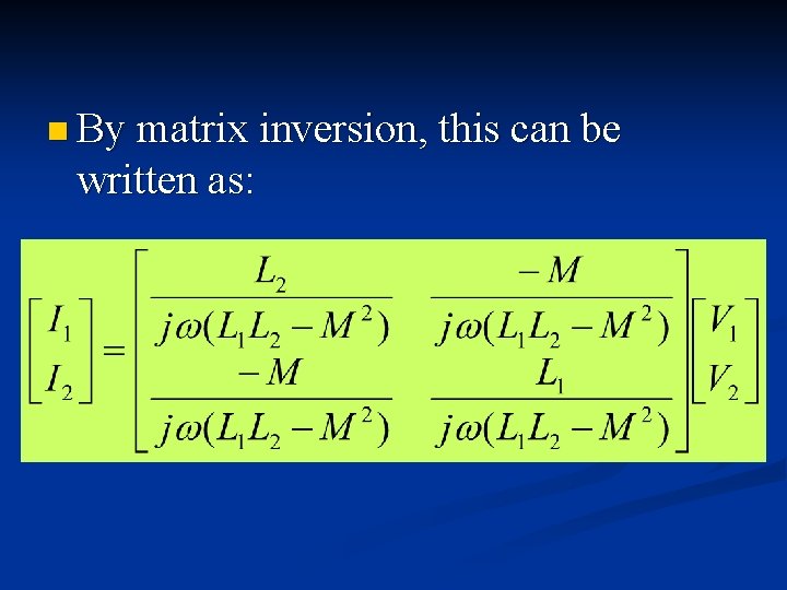
n By matrix inversion, this can be written as:
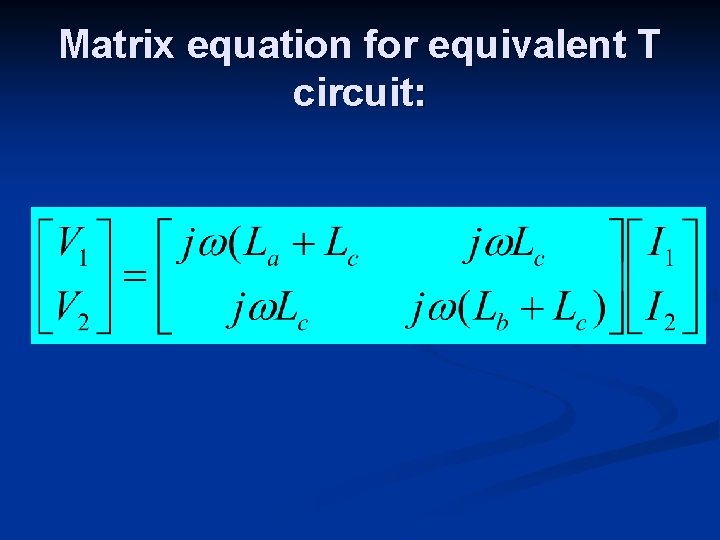
Matrix equation for equivalent T circuit:
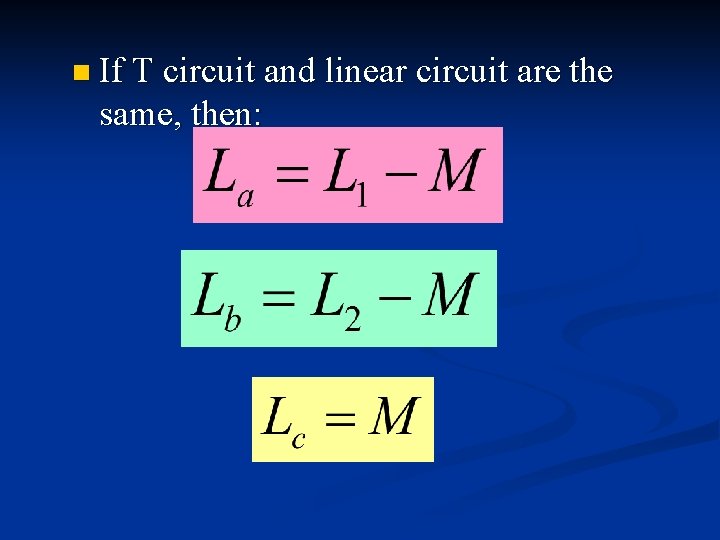
n If T circuit and linear circuit are the same, then:
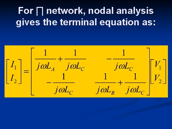
For ∏ network, nodal analysis gives the terminal equation as:
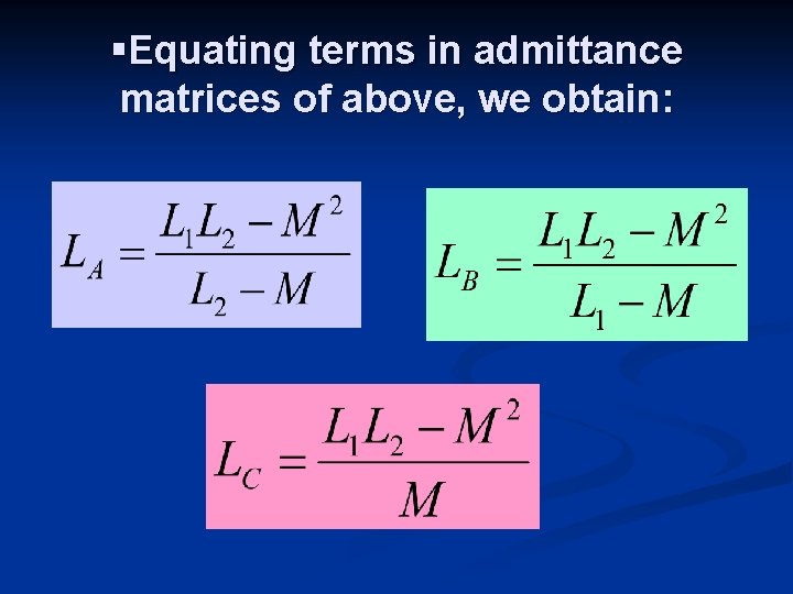
§Equating terms in admittance matrices of above, we obtain:
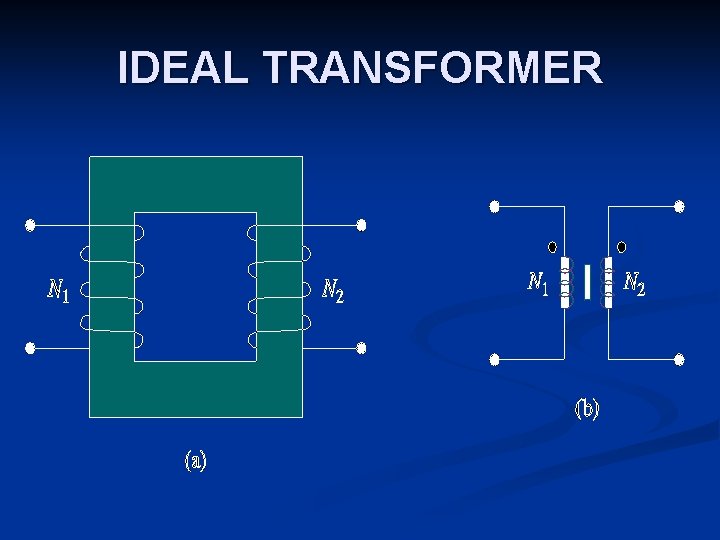
IDEAL TRANSFORMER
Properties of ideal transformer: Coils have very large reactances (L 1, L 2, M→∞) n Coupling coefficient is equal to unity (k=1) n Primary and secondary winding are lossless (R 1=0=R 2) n Ideal transformer is a unity-coupled, lossless transformer where primary and secondary coils have infinite self-inductance.
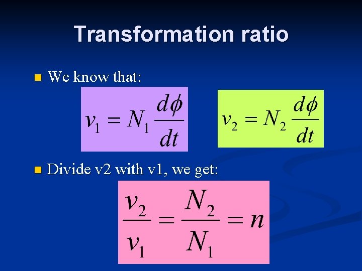
Transformation ratio n We know that: n Divide v 2 with v 1, we get:
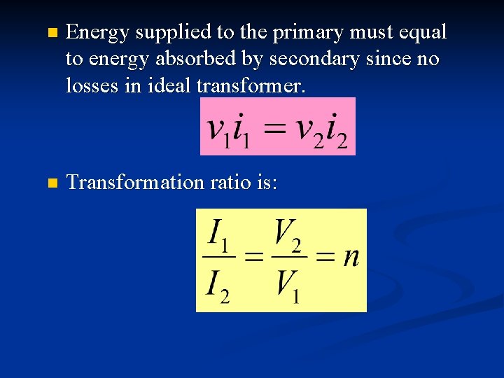
n Energy supplied to the primary must equal to energy absorbed by secondary since no losses in ideal transformer. n Transformation ratio is:
Types of transformer: n Step-down transformer One whose secondary voltage is less than its primary voltage. n Step-up transformer One whose secondary voltage is greater than its primary voltage.
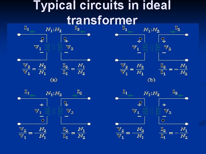
Typical circuits in ideal transformer
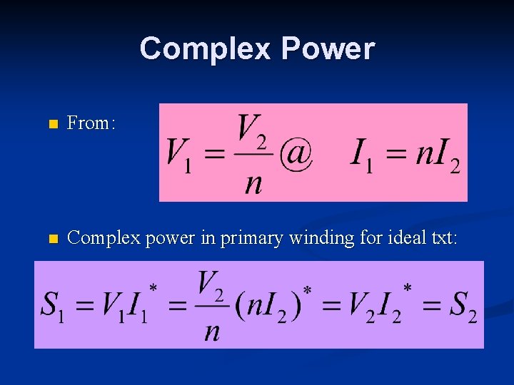
Complex Power n From: n Complex power in primary winding for ideal txt:
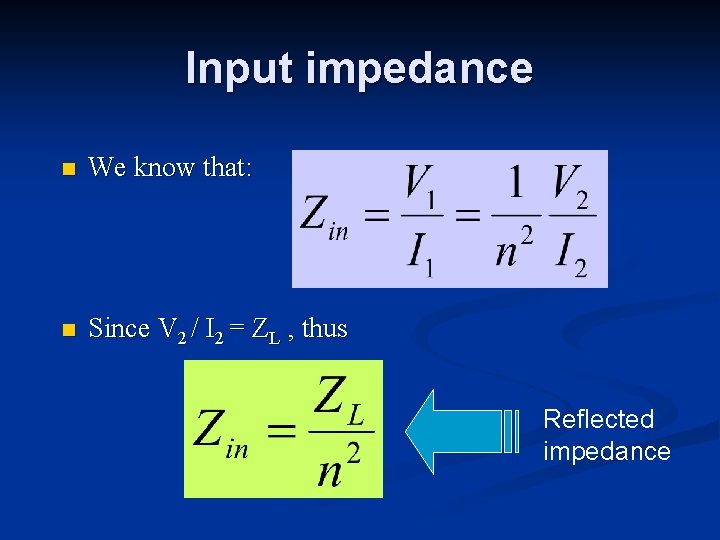
Input impedance n We know that: n Since V 2 / I 2 = ZL , thus Reflected impedance
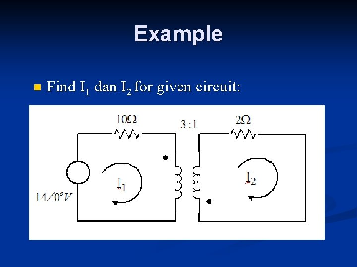
Example n Find I 1 dan I 2 for given circuit:
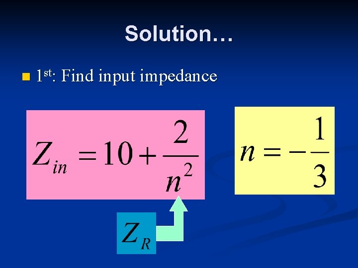
Solution… n 1 st: Find input impedance
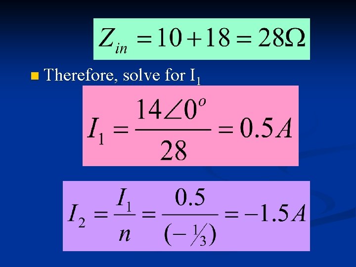
n Therefore, solve for I 1

THE END
- Slides: 69