Liquid Molding RTM Resin Transfer Moulding RTM Resin

")
")


 Schraubzwinge Spannrahmen Dichtung gelochtes Blech Rinne")
 • The")
 • Different materials characterized by a high permeability to")
 Plastic wires are weaved so that")
")
 Plastic base net by Colbond (Enka –")
 distribution media")
 and lay up Lantor Soric® (Lantor Composites)")


 • RFI (Resin Film Infusion) – A film")
 • RFI (Resin Film Infusion)")
 was patented")

 was patented by EADS")
 is a Bombardier patented")


 Good")
")
 DP/L")


 , t*=t/tgel e L= flow length, Pi=")

![Permeability Physical dimensions [K] = [h V L /P] = [P t L t-1](https://slidetodoc.com/presentation_image_h2/676b94df5dbf45397b53c14398fd63aa/image-44.jpg "Permeability Physical dimensions [K] = [h V L /P] = [P t L t-1")


 • The relationship between the pressure drop and")


 Depending on the capillary number,")
 Intrabundle or micro voids are")


 supported by")


 – The")


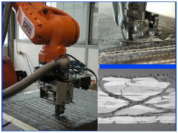
 transport system, B) UD tape feeder, C) Braider")
")


 Leonardo aerostructures Adv. Composites sept. 2013")
: disadvantages of stitching")
: advantages of stitching")


 similar to strain gage in critical")

 and")


- Slides: 97
Liquid Molding
RTM (Resin Transfer Moulding)
RTM (Resin Transfer Moulding)
“Alphabet soup” of RTM-type processes • RTM – – A technology developed starting from polyurethane reactive injection Injection in a closed mold in presence of a reinforcement preform Typical fibre content 30%-50% by volume, P about 6 -10 bar Sandwich panels with foam cores • VARTM (Vacuum assisted RTM) – Vacuum is applied to reduce he void content. A slight pressure increase is also obtained. – Vacuum in the range 700 -900 mbar – - higher cost of equipments and molds • RTM light – One of the mold is made using a composite laminate – Vacuum is used but lower positive pressures allowed in comparison with RTM
RTM vs. VARTM • RTM – Both molds are made of steel or aluminum and are ususally put in a press. – In absence of vacuum the air is pushed out by the resin. – The injection is usually in a single point or in aline at the mold edge. • VARTM – Equipment similar to those adopted for RTM – Vacuum is applied – Metal tooling with seals for vacuum
RTM vs. RTM light • RTM – Both molds are made of steel or aluminum and are ususally put in a press. – In absence of vacuum the air is pushed out by the resin. – The injection is usually in a single point or in aline at the mold edge. • RTM light: – With one of the mold in GFRP (or CFRP) max positive pressure is 1 bar – Vaccumm is applied at the cemter and injection occurs along the perimeter, using a proper feeding channel
Vacuum assisted resin distribution or resin infusion (VARI) Schraubzwinge Spannrahmen Dichtung gelochtes Blech Rinne für überflüssiges Harz Folie Verstärkung mit Laminat Trennschicht festes Werkzeugunterteil Ventil zur Vakuumpumpe Vakuumbehälter für überflüssiges Harz A resin trap an perforated release films are tipically used
“Alphabet soup” of RTM-type processes SCRIMP (Seeman’s Composite Resin Infusion Molding Process) • The resin is sucked into the dry fibres thanks to vacuum • an open mold is used. Vacuum bagging is applied • In SCRIMP process the first resin distribution media were patented
Resin distribution media (or nets) • Different materials characterized by a high permeability to the resin can be used as resin distribution media. • High permeability is required under vacuum, i. e. under 1 bar pressure. • The resin distribution medium acts also as breather when vacuum is applied • The use of a resin distribution medium or of a resin distribution net promote an in-plane flow in this high permeability material while the impregnation of the reinforcements is achieved by an out-of-plane (through-thickness) flow
Resin distribution media or resin distribution nets (external) Plastic wires are weaved so that the resin can flow in the same way in the two directions
Resin distribution nets (external)
Resin distribution nets (internal, acting as cores) Plastic base net by Colbond (Enka – Spacer 7008) Lantor Soric® (Lantor Composites)
Internal (core) distribution media
Resin distribution nets (internal) and lay up Lantor Soric® (Lantor Composites)
Grooved cores
Resin infusion through a grooved core
Liquid moulding in wind blade skins PVC and balsa with distinctive groovings to enable the DIAB method of core infusion for the fabrication of 83 m wind blade. Each blade skin was produced in a female mould using a combination of VARTM (vacuum assisted resin transfer moulding), pre-preg and hand lamination
Resin infusion of a sail boat hull
Resin infusion of a sail boat hull: rinforcement at the mast base
Resin infusion for a boat hull: deck
Resin infusion of a boat hull: deck
“Alphabet soup” of RTM-type processes (II) • RFI (Resin Film Infusion) – A film of resin (high viscosity, poor or no tack) is stacked together with a dry reinforcement in a typical tool used for autoclave lamination – Vacuum bagging and auxiliary materials formerly described are used – Impregna tion and cure occurs in an autoclave – Impregnation occurs when the viscosity decreases to the minimum befor gelation – Transversal flow is limited to ply thickness distance
“Alphabet soup” of RTM-type processes (II) • RFI (Resin Film Infusion)
“Alphabet soup” of RTM-type processes • CAPRI (Controlled Atmospheric Pressure Resin Infusion) was patented by Boeing – it reduces thickness variation and results in fiber volumes and mechanical properties equivalent toprepreg/autoclave materials. – First it uses vacuum debulking cycles on the dry preform to reduce compressed thickness prior to infusion. – During infusion, the resin supply is held at partial vacuum, which assists in degassing the bulk resin but also reduces the pressure differential driving resin into the preform. – Curing in autoclave or out of autoclave
“Alphabet soup” of RTM-type processes Rocco. Rametta@avioaero. com
“Alphabet soup” of RTM-type processes • VAP (Vacuum Assisted Process) was patented by EADS – it is used in parts like the A 380 Aft Pressure bulkhead and the massive A 400 Cargo Door. – VAP features a gas permeable membrane placed over the infused layup, which helps to evacuate trapped air and volatiles in the infused layup prior to cure. – By letting gases through the membrane (but not the resin) VAP is said to achieve lower voids and higher, more controlled fiber volume for better laminate quality • RTI (Resin Transfer Infusion) is a Bombardier patented process used to produce the wing skins of its CSeries aircraft – Infusion of resin into the preform is performed with vacuum pressure only. – However, the mold is located in an unpressurized autoclave during the infusion step. After the preform is fully infused, the autoclave is pressurized and heated to perform cure. – This makes it easier to achieve high laminate quality because positive cure pressure (>14 psi) helps prevent void formation from entrapped air and volatiles. It has the drawback that a suitable size autoclave is still requited.
“Alphabet soup” of RTM-type processes • RTI (Resin Transfer Infusion) is a Bombardier patented process used to produce the wing skins of its CSeries aircraft using dry carbon fiber non-crimp fabric (NCF) – The NCF has a binder, which is used in preforming on a male tool, followed by infusion in a female tool – The tool is preheated, the part is bagged and the resin (Cytec’s Cycom 890, for resin transfer molding) is injected with vacuum pressure only. – However, the mold is located in an unpressurized autoclave during the infusion step. After the preform is fully infused, the autoclave is pressurized and heated to perform cure. – This makes it easier to achieve high laminate quality because positive cure pressure (>14 psi) helps prevent void formation from entrapped air and volatiles. It has the drawback that a suitable size autoclave is still requited. – Stringers are co-cured with the upper and lower wing skins
RTM processes and toughned epoxy resins • • • Toughned epoxy resins contains thermoplastic chain segments among the oligomers used in the formulation. These are functionalized (epoxy or amine terminated) to react with the other monomers. These compounds are responsible of a signifcant increase of the resin viscosity, too high for RTM (A in figure) Soluble powders of fibers (Fig. 7) made of the toughening agents are adopted injection is performed with a low viscosity resin toughening occurs after dissolution of thermoplastic powder of fiber Epoxy resin viscosity during heating at constant rate: A: Too viscous , B: too fast kinetic, C: Viscosity profile needed for RTM
toughned epoxy resins: Priform process • Temperature profile for Priform process: – – Toughening fibre dissolution occurs after mold filling Phase separation is the mechanism where thermoplastic domains are formed during curing, leading to a toughened crosslinked polymer.
Benefits of RTM • • Low capital investment (low pressures 6 -8 bar) Good surface quality Tooling flexibility Large, complex shapes Ribs, cores and inserts Parts integration Range of available resin systems (all resins with viscosity lower than 0. 8 Pa s) • Range of reinforcements (all fibers) • Controllable fiber volume fraction
A “good” RTM resin (0. 2 Pa s)
Darcy experiments on flow in porous media V=Q/A= -(K/h) DP/L
Darcy vs. Navier-Stokes Integration of Navier-Stokes eqn for a tube in steady state provides the flow rate q, called Hagen-Poiseuille equation: The average velocity is : Assuming as Permeability coefficient K: Dividing by the cross section area Darcy equation is obtained: 2 R q y x z In a porous medium with ni cylindrical pores of radius Ri the flow rate is: h i=1, N( number of cylindrical pores) b
Darcy Equation Local Reynolds number = rv. D/h<1 laminar flow among pores Darcy Equation V = - [K]/h (ÑP-rg) Vi= -1/h (Ki 1¶P/¶x 1+Ki 2 ¶P/¶x 2+Ki 3¶P/¶x 3) where: [K] = permeability matrix V = Q/A ed h = h(T, a) Often g can be neglected and Kij = 0 per i¹j Kij¹ 0 per i=j V 1=-1/h K 11¶P/¶x 1 Vx=-1/h Kxx¶P/¶x V 2=-1/h K 22 ¶P/¶x 2 Vy=-1/h Kyy ¶P/¶y V 3=-1/h K 33¶P/¶x 3 Vz=-1/h Kzz¶P/¶z
Continuity Equation For an an incompressible flow field ¶Vx/¶x +¶Vy/¶y+ ¶Vz/¶z=0 Substituting Darcy equation: ¶/¶x(Kxx/h ¶P/¶x)+¶/¶y(Kyy/h ¶P/¶y)+¶/¶z(Kzz/h ¶P/¶z)=0 If K and h do not depend on x, y and z : ¶ 2 P/¶x 2+¶ 2 P /¶y 2+¶ 2 P/¶z 2=0 and in 1 D ¶ 2 P/¶x 2=0
Integration of the continuity equation in 1 D Integrating ¶ 2 P/¶x 2=0 P=C 1+C 2 x is obtained P Pi L xf B. C. : P=0 at x=xf (front position) xf P=Pi at x=0 (Injection pressure Pi assumed constant at x=0) x P=Pi(1 -x/xf) the velocity (plug flow), given by Darcy eqn. decreases as xf increases A steady state equation for an unsteady state problem? The entrance length, where the velocity profile changes, is given by Li@ 0. 05 D Re but. D @ 10 -5 m and Re @10 -1 10 Li is very small, of the order of 10 -7 m
Front position in 1 D flow • Darcy equation in 1 D is: V = - K/h d. P/dx • Assuming steady state flow at each time instant and being the flow incompressible, a plug flow occurs where velocity id given by V=dxf/dt • If injection ia achieved at constant pressure (DP=const. ) then dxf/dt= - K/h DP/xf • Integrating for constant permeability and viscosity separating the variables : xdx=- K/h DPdt tra [0, xf] e [0, tf] L xf
Front position in 1 D flow • The calculation of the permeability of the reinforcement or of the distribution net can be made for the technology of resin infusion with a simple experimental set-up using the vacuum bag (usually transparent) and by recording the position of the front at different infusion times • The slope of the plot of resin front position vs. t 0. 5 is: L xf
Permeability measurement The measurement of permeability can be also done by: • plotting flow rate vs. pressure drop for a one-dimensional flow experiment, and • measuring the slope of the linear portion of this graph.
Filling time 1 D • Starting from the integration of dx/dt=- K/h DP/x it is possible to obtain the filling time, tr , i. e. the time needed to fill a mold length equal to L: tr can be compared with tgel or to the induction time, obtained by rheological and/or calorimetric experiments
Effect of viscosity changes • As the resin polymerizes, the viscosity of the resin increases. • The gel time is the time at which there is a sharp rise in the viscosity of the resin as it starts to solidify into a cross-linked structure. • Gelation sets the time available for filling large parts. • The resin formulation may be changed to suit processing conditions. Epoxy resin Unsaturated Polyester resin
Dimensionless Darcy equation Dimensionless variable are: x*=x/(L/2) , t*=t/tgel e L= flow length, Pi= injection pressure DP*= DP/(Pi /2) Darcy eqn. dx/dt=- K/h DP/x becomes: Where again Deborah is the ratio of two time scales: Obviously De. D>1 is always required in order to completely fill a mold
Fast curing resin for RTM • Epoxy and polyurethanes • High cure temperature materials • Automotive applications • Very low filling time required
Permeability Physical dimensions [K] = [h V L /P] = [P t L t-1 L P-1]= [L 2] Permeability depends on: • Porosity (f= 1 - vf) • Type of reinforcement (glass, carbon etc. ) • Shape and dimensions of pores • Sizing of fibres and type of resin (polyester, epoxy etc. ) In each direction K i proportional to f and to fibre radius Rf Kii = Cii (R 2 f/4) [f 3/(1 -f)2 ] Cii = Carman-Kozeny constant Since it is not true that when porosity is zero then Kii =0, a limiting porosity value flim=(1 -vfmax) at which Kii 0 is introduced Kii = Cii (R 2 f/4) [(vfmax /vf-1)0. 5]3/[vfmax /vf+1]
Anisotropic flow in RTM • Permeability for fluid flow in the plane is generally higher than its permeability for the fluid in the transverse or out-of-plane direction. (i. e. For a unidirectional woven Kzz<Kxx and Kzz<Kyy but also Kxx>Kyy; for a balanced woven fabric Kxx = Kyy)
Effect of preform compressibility The same reinforcement can be characterized by a different permeability depending on the fiber content, i. e. the thickness defined by mould and plug in RTM and the vacuum achieved in VARI
Pressure drop in RTM (Darcy law) • The relationship between the pressure drop and the flow rate is linear and indicates the applicability of Darcy's law in both cases. • Knowing fluid viscosity, the length L and cross-sectional area A of the preform, its permeability can be calculated from the slope of the graph. • For the higher fiber volume fraction of 0. 69, the slope is much less than the slope for the lower fiber volume fraction of 0. 49. This shows that for higher volume fraction the preform permeability is much less, although both the preforms are made from the same uni-directional plies.
1 D flow in layers with different permeability • In reality, variations in permeability through the thickness of the part lead to racetracking and other non-plug flow profiles, so the simplified scheme is not perfectly accurate.
Modeling of mold filling Materials • Numerical solution of continuity and Darcy equations is needed when the geometry is complex or when the flow is 2 D with layers characterized by different permeability. • In VARI a faster flow is expected in the resin distrinìbution net (see next slide) L a m i n a t e A u x il i a r i e s P a r a m e t e r s Resin Reinforcement viscos ity [Pa·s] type 0. 165 Carb on fibre UD porosi ty 0. 4 thickn ess [mm] permeability [m 2] KX KY KZ 4 E-11 7. 6 E-12 8 E-13 0. 2 Resin Distribution Fabric porosi ty 0. 9 thickn ess [mm] 0. 5 Peel Ply porosi ty permeability [m 2] KX KY KZ 9 E-06 3 E-04 0. 7 thickn ess [mm] 0. 1 permeability [m 2] KX KY KZ 8 E-08 8 E-07 Temperature [K] Pressure inlet [Pa] Pressure outlet [Pa] 300 80000 0
Modeling of mold filling • In this case the top layer is a resin distribution net, where the flow is much faster than in the carbon fibre reinforcement The top layer is almost completely filled while out of plane flow is not yet capable to fill the reinforcement
Grooved core: modeling of filling • In VARI of sandwich structures grooved cores can be adopted as flow media: they are foams with channels and holes. • The simulation is obtained using Darcy and continuity equations, assigning an equivalent permeability to channels, depending on their shape (usually squared) (flow equations imply linearity between flow rate and DP/L)
Grooved core: modeling of filling • A carbon fibre fabric is adopted L a m i n a t e A u x i l i a r i e s P a r a m e t e r s Materials Resin Reinforcement viscosity [Pa·s] type porosity thickness [mm] 0. 165 Carbon fibre UD 0. 4 0. 2 permeability [m 2] KX KY KZ 4 E-11 7. 6 E-12 8 E-13 Primary channels cross section [mm] 5 x 2 type array of 10 x 10 units Secondary channels permeability [m 2] KX KY KZ 2. 3 E-07 cross section [mm] type 5 x 2 array of 10 x 10 units permeability [m 2] KX KY KZ 2. 3 E-07 Temperature [K] Pressure inlet [Pa] Pressure outlet [Pa] 300 80000 0
Grooved core: modeling of filling • Modeling of a row of 10 regular meshes 9 x 9 cm: • Channel positions and mesh size can be modified according to the gel time of the resin
Microscale flow • There are two scales of resistance to flow through preforms: resistance between the tows and resistance in the tows. • Even when a part appears completely filled, microvoids may remain if the resin does not wet the entire tow. This is more prone to happen at higher fiber volume fractions. • The pictures shows the tows as circles and the junctions as the areas around the tows. The flow entering can go past the tows without fully impregnating them.
Micro-scale and meso-scale flow • The flow front comes around fiber tows and actually passes it. However, the fluid continues to impregnate the tow after the flow front has passed. • If the air was not evacuated at the beginning of the filling process, air is trapped in the tow and so a microvoid is formed at the center of the tow.
Microscale flow Fibre Bundles flow front
Microscale and macroscale flow Permeability is different for the two type of matrix flow depending on porosity and tortuosity Resin Pressure forces are dominant on capillary forces high DP Typical of thermoplastic matrix impregnation Kmacro = Cmacro (R 2 bundle/4) [fmacro 3/(1 -fmacro)2 ] Kmicro = Cmicro (R 2 f/4) [fmicro 3/(1 -fmicro)2 ] Capillary forces are dominant on pressure forces very low DP Thermosetting resin: hand lay up Resin
Micro e macro flow in resin transfer moulding (RTM) Depending on the capillary number, Ca= hv/g: a)Intrabundle or micro voids are observed. b)Interbundle or meso-scale voids are observed Void content Usually the velocity, v, make the capillary number (>10 -4) Only intrabundle voids are expected 10 -4 P Ermanni, Composite A, 2007
Micro e macro flow in resin transfer moulding (RTM) Intrabundle or micro voids are observed. Direction of flow Mizutani, Adv. Comp. Mat. 2013
Darcy flow in autoclave lamination • Step 1: room temperature very high viscosity • Step 2: Temp. ibìncreases, viscosity decreases and the liquid escapes from the. Fiber bed is compacted • Step 3: the fiber beds start carrying load and its permeability reduces: the resin flow decreases • Step 4: if gelation is not occurred all the load is carried by spring (compacted fiber bed) the hydrostatic pressure in the liquid drops and void formation is likely to occur
Process modeling: Vacuum bagging At room temperature: • there is no flow • The top ply in the stack is kept under vacuum (between -700 and -980 mbar depending on the process) Autoclave pressure reduces the breather thickness. An Airtech single layer of breather under 9 bar pressure with a thickness of 0. 5 mm was adopted vacuum as a The resin flow in autoclave process can be sketched dashpot and a spring in parallel (a Maxwell-Voigt viscoelastic element). breather The spring represents the stiffness of the reinforcement laminate The dashpot the viscous drag due to resin flow tool
Darcy flow in autoclave lamination: heating and resin flow During heating: • viscosity decreases • A pressure gradient is developed across the lay up • The resin flows through composite thickness filling the breather (in plane flow is neglected) under autoclave pressure • The upper resin layer still under vacuum Resin filled breather Unfilled breather Resin front position xf
Darcy flow in autoclave lamination: end of flow, pressure build up When the resin touch the vacuum bag: • The flow ends • The pressure is distributed between those supported by the reinforcement, under compression strain, the hydrostatic pressure in the resin is constant • The resin pressure is always lower than autoclave pressure vacuum bag/resin contact
A three stage process and the viscoelastic model autoclave pressure vacuum bleeder laminate tool • Room temperature • No flow. • Eventual lost of volatiles by diffusion • Heating: reinforcement compaction and flow. • Still possible volatile extraction • vacuum bag in contact to resin • Flow end Pressure is distributed between the spring (elastic reaction of fiber stack) and the dashpot (hydrostatic pressure in the resin)
Other possible causes for flow end vacuum Resin filled breather Unfilled breather Resin front position xf The resin flow ends when: • the bleeder is filled of resin(as formerly described) or • the spring takes all the load or • resin viscosity is very high and the dashpot becomes not deformable
Modeling of pressure distribution The total pressure, i. e. autoclave pressure is given by: Paut=Psp+Pdp Spring pressure (Psp) is given by a non linear relationship: Psp =A 0 exp(e/A 1)-A 0 - A 0 and A 1 are assumed constant Stiff fiber stack Vf about 45% Paut X Pdp Psp compliant fiber stack Vf about 60%
Darcy flow in autoclave lamination: Modeling of pressure distribution The stress (pressure) supported by the dashpot was obtained assuming a Darcy flow across the reinforcement stack in 1 D across the thickness - Lateral flow is neglected Pdp = (de/dt) ttoth(T, a)/Kf (tc -ettot) The Viscosity h depends on Temperature and Degree of reaction ttot= total thickness=stack (tc) +breather thickness Paut Kf is the permeability of the reinforcement and depends on fiber content Vf Therefore a first order differential eqn is obtained, P dp where e[a(T, t), h(a, T)] is the unknown: Paut=Psp(e) +Pdp (e, de/dt) X Psp
Darcy flow in autoclave lamination: Stress in the fiber stack and resin pressure Laminate thickness =12 mm • Compliant fiber stack • Bleeder thckness 0. 5 mm • Heating rate =0. 5 o. C/min • Autoclave pressure 9 bar üHigh laminate thickness üBleeder is filled but with a limited strain of fiber stack üAutoclave pressure is almost equal to equilibrium resin pressure equilibrium hydrostatic resin pressure
Hydrostatic resin pressure measurements • The stiff screen prevents deflection into the hole in contatct with the pressure transducer • Test with high and low flow resins in UD laminates • 10 to 40 plies Campbell, J. Adv. Mat. 1995
Darcy flow in autoclave lamination: thick laminates No porosity • • • Thicker laminates maintain a higher pressure compared to thinner ones Resin flow is associated to resin pressure decrease Resin flow is promoted by viscosity decrease and is associated to a decrease of the resin pressure Campbell J. Adv. Mat. 1995
Darcy flow in autoclave lamination: Stress in the fiber stack and resin pressure Autoclave pressure 9 bar, overbleeding and stiff fiber stack • Heating rate =0. 5 o. C/min • Bleeder thickness = 0. 5 mm • Laminate thickness =4 mm üThick bleeder and stiff fiber stack üIncomplete filling of bleeder üall autoclave pressure is supported by the fiber stack üResin pressure is 0 when viscosity is not yet at its minimum Elastic stress=autoclave pressure
Darcy flow in autoclave lamination: thin laminates zero pressure Gross porosity • Using additional bleeders (overbleeding) large resin flow is allowed and the fiber stack is deformed up to its limit, i. e. up to a stress equal to autoclave pressure Campbell J. Adv. Mat. 1995
“Alphabet soup” of RTM-type processes • SQRTM (Same Qualified Resin Transfer Molding) – The lay up is done with prepregs using aeronautic “Qualified” materials – A close mold is used. The molded is heated or placed between the heated plates of a press – The “Same Qualified” resin is injected in order to reach a constant hydrostatic pressure in the mold, the same set for an autoclave cycle. - This should dramatically reduce voids using materials developed for autoclave curing.
Mat preforms for RTM Advantages Disadvantages • High permeability • Easily infused • Easy handling • Poor stiffness • Limited strength • No orientation control • Limited fiber volume fractions
Woven fabric for RTM Advantages Disadvantages • Balanced properties in the plane of the fabric • Good impact resistance • Fiber undulation • Asymmetry • Trimming / Handling • Good conformability UD fabric for RTM Advantages Disadvantages Higher stiffness and strength in filament direction Poor integrity - "fiber wash" may occur Anisotropic flow and performance
Directed fiber preforming
Braiding A close profile is obtained with a plain weave with a + q angle
Overbraiding • During overbraiding the preform is fabricated on a core, which has the inner geometry of the desired preform • By reciprocating the core through the braiding point a preselected number of layers can be braided • The core is usually removed
Overbraiding
Braiding C-frames of A 350 A square section is overbraided on a squared section profile and then cut along a mid plane to obtaine two C profiles. The profiles are used in a resin film infusion process.
Braiding C-frames of A 350 The over braided square section is completed with a 0°UD tape and a second braided + q layer (left). Finally a 90 tape is applied (right).
Braiding C-frames of A 350 A) transport system, B) UD tape feeder, C) Braider #1, D) 90° tape winder, E) Braider #2
Stitching e Non Crimp Fabrics (NCF)
Multiaxial Non-Woven Fabrics Guiding rolls creel fibers collecting rolls Stitched multiaxial Fiber mat bobins Stitching machine Deposition combs Needle feed chain
Resin Film infusion stitched preform for aircraft wing panel Courtesy sigmatex
Stitched preforms (2 D and 3 D) Leonardo aerostructures Adv. Composites sept. 2013
Non Crimp Fabrics (NCF): disadvantages of stitching
Non Crimp Fabrics (NCF): advantages of stitching
Visual Inspection and Damage Criteria • Typical internal damage from Barely Visible Impact – Barely Visible Impact Damage (BVID) is defined as damage not found during heavy maintenance surveillance inspections from a viewing distance of five (5) feet, under typical lighting conditions. Impact Location
Inspection of In-Service Damage • Visual Inspection is the principal method of damage detection • Instrumented NDI required only when visible damage beyond ADL exists Visual detection NDI to determine extent of damage Repaired NDI for post repair inspection
787 Structural Health Management Configuration Sensors (eddy current) similar to strain gage in critical points Sensors RDC Cargo and aft service doors (typical) Fwd cargo door Aft cargo door Sensor locations SHM-007
Preforming methods
Critical factors in RTM • • • Fibre impregnation Viscosity (and its changes) and resin flow Filling time Welding lines Applied pressure (size and cost of molds and presses) Fabrication of preforms
Advantages of liquid molding in comparison to open mold processes • Production of large monolithic parts • Good control of fiber content • Possibility of producing sandwich structures and introduce inserts • Good finish on all surfaces for RTM in closed mold • Good control of thickness and dimensional tolerances • Cycle times shorter than those of open mold technologies • Reduced emission of VOC (Volatile Organic Compounds)
Dry OOA in aeronautic • • • The MS-21 -300 ( Irkut Corp. (Irkutsk, Russia) (160 -211 passengers), First flight in may 2017, certification started in the 2019 EASA (European Union Aviation Safety Agency). First out-of-autoclave (OOA) composite wing and wing box on a commercial aircraft. The layup is done via placement of unidirectional dry fiber (but with a binder) with automated tape laying (ATL) equipment provided by MTorres (Spain) and Coriolis (France). • The resin (Cytec) is “a unique product that is toughened and infusible without having to introduce tougheners in other forms like films or polymer fibers. ” • Further, the resin offers a long window for the infusion process, which provides more than adequate time for large primary structures such as wings. The result, is very low porosity in the final part that “is equal to or less than in an autoclave. ” • MS-21 stringers and skins are co-molded in one piece, with the spars and wing box fabricated separately.
Wind turbine blades Adhesive bonding extensively used