
Liquid BiPropellant Thruster Concept Design Review Adam Pender
Liquid Bi-Propellant Thruster Concept Design Review Adam Pender Jason Wennerberg Arun Padmanabhan Josh Revenaugh 2/10/2005 Thrust Chamber Assembly Concept Design Review 1
Outline • • • Schedule and Milestones Mission System Requirements Compliance Matrix Design Process Concepts Considered Chosen Concept Details Application to SLV Project Conclusion 2/10/2005 Thrust Chamber Assembly Concept Design Review 2
Schedule Milestones • Concept Design Review – Now. • Preliminary Design Review – March 4 • Critical Design Review – April 7 • Hardware Completed – May 5 2/10/2005 Thrust Chamber Assembly Concept Design Review 3
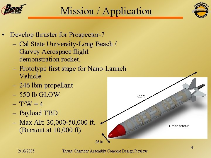
Mission / Application • Develop thruster for Prospector-7 – Cal State University-Long Beach / Garvey Aerospace flight demonstration rocket. – Prototype first stage for Nano-Launch Vehicle – 246 lbm propellant – 550 lb GLOW – T/W = 4 – Payload TBD – Max Alt: 30, 000 -50, 000 ft. (Burnout at 10, 000 ft) ~22 ft Prospector-6 26 in 2/10/2005 Thrust Chamber Assembly Concept Design Review 4
Requirements • • • Thrust: 2200 lbf Chamber Pressure: 300 psi Burn Time: 20 seconds Nozzle Designed for Sea Level to 10, 000 ft. Operation O/F = 2. 27 (propellants deplete at same rate) Thruster Mass < 15 lbm Injector Pressure drop of 70 psi C* efficiency of 95% Interface – AN fittings (-8 if possible) – 10+ inch plate with bolt pattern communicated to CSULB • Development Static Tests Performed at Purdue 2/10/2005 Thrust Chamber Assembly Concept Design Review 5
Pre-Launch Test Requirements • Engine-only Static Test – Verify Performance • Rocket Static Test – Verify Engine/Rocket Integration – 2 -4 Seconds if engine to be reused • Static tests may be performed by CSULB at Mojave 2/10/2005 Thrust Chamber Assembly Concept Design Review 6
Requirements Compliance • Interface: Document Fittings and Flange Bolt Pattern • Nozzle: Design with Area Ratio for Max Efficiency from 0 -10, 000 ft. • Thrust, Burn Time, C* Efficiency, O/F : Static Tests • Thruster Mass: Scale 2/10/2005 Thrust Chamber Assembly Concept Design Review 7
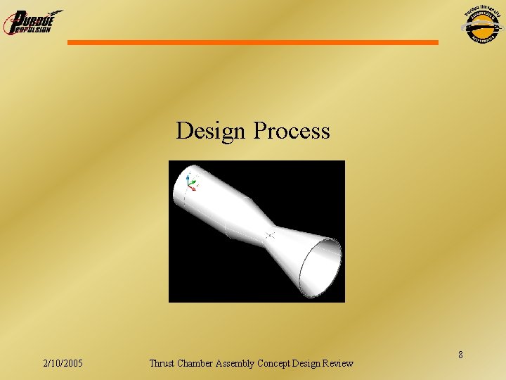
Design Process 2/10/2005 Thrust Chamber Assembly Concept Design Review 8
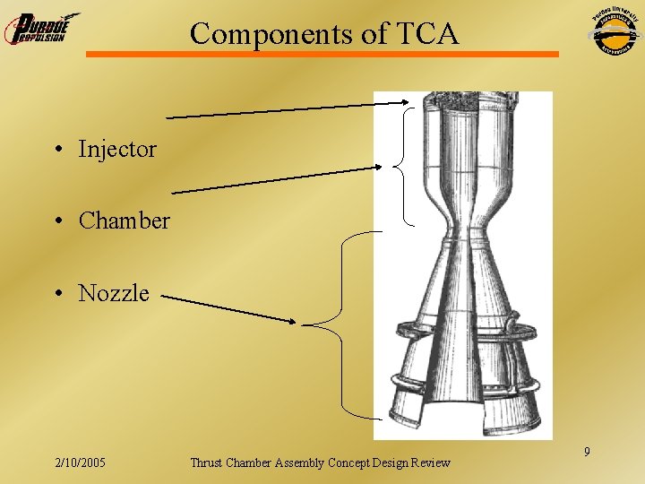
Components of TCA • Injector • Chamber • Nozzle 2/10/2005 Thrust Chamber Assembly Concept Design Review 9
Design Process • The first step in the design was to pick propellants – LOX – propene chosen for several reasons • Performance is increased over LOX - RP-1 • Customer has experience and access • Allow for partial self pressurization of propellant tanks • The mixture ratio is specified by CSULB based on the ratio that will give the best operability = 2. 27 • A chamber pressure must be chosen – 300 psi was chosen by the customer. • Current tanks can handle 450 psi 300 psi chamber pressure after losses • Cooling by passive means is possible (No dump or regenerative cooling required) 2/10/2005 Thrust Chamber Assembly Concept Design Review 10
Design Process • With the information available we run the NASA thermochemistry code to obtain some useful data: – – – – Chamber Temp (Tc) = 6374 R C* = 6073 ft/s Exit pressure (pe) = 5. 7 psi Exit velocity (ve) = 9673. 5 ft/s Cfvac = 1. 593 Specific heat ratio γ = 1. 1396 Molecular weight = 21. 232 Ispvac = 329. 3 s 2/10/2005 Thrust Chamber Assembly Concept Design Review 11

Design Process With this data we can continue with the design of the engine. We would like to use the equation that relates mass flow rate to force and Isp so first we need Cf at sea level, and then Isp at sea level and then finally mass flow rate through the engine. From NASA code Design parameters From NASA code Design parameter 2/10/2005 Thrust Chamber Assembly Concept Design Review 12

Design Process We know our O/F ratio so we can then split the mass flow into fuel and oxidizer: Where r is the mixture ratio The throat area is found with: We want the diameter of the chamber to be at least twice the diameter of the throat to help with combustion stability 2/10/2005 Thrust Chamber Assembly Concept Design Review 13
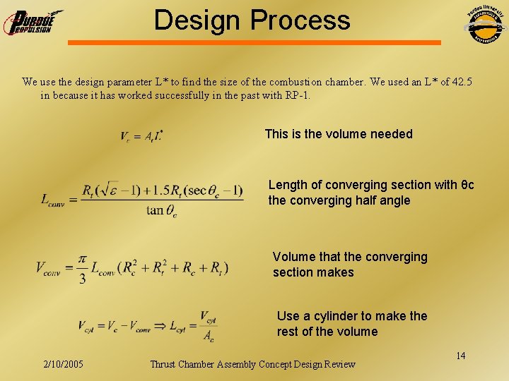
Design Process We use the design parameter L* to find the size of the combustion chamber. We used an L* of 42. 5 in because it has worked successfully in the past with RP-1. This is the volume needed Length of converging section with θc the converging half angle Volume that the converging section makes Use a cylinder to make the rest of the volume 2/10/2005 Thrust Chamber Assembly Concept Design Review 14
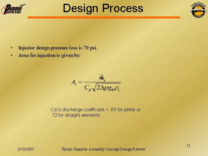
Design Process • • Injector design pressure loss is 70 psi. Area for injection is given by: Cd is discharge coefficient =. 65 for pintle or. 72 for straight elements 2/10/2005 Thrust Chamber Assembly Concept Design Review 15
Design Requirements – Chamber • L* = 42. 5 in • Should withstand heat flux for burn time • Should not be overly complicated (Cheap to build) • Cannot use regenerative cooling because of lack of pressure budget • Use ablative liner or thermal barrier coating and O/F biasing for cooling • Convergence ratio of 3. 5 -4 2/10/2005 Thrust Chamber Assembly Concept Design Review 16
Design Specs - Chamber • • Chamber Diameter = 5 in Length of chamber = 9. 32 in Length of converging section = 3. 63 in Diameter of throat = 2. 61 in 2/10/2005 Thrust Chamber Assembly Concept Design Review 17
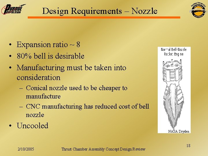
Design Requirements – Nozzle • Expansion ratio ~ 8 • 80% bell is desirable • Manufacturing must be taken into consideration – Conical nozzle used to be cheaper to manufacture – CNC manufacturing has reduced cost of bell nozzle • Uncooled 2/10/2005 NASA Dryden Thrust Chamber Assembly Concept Design Review 18
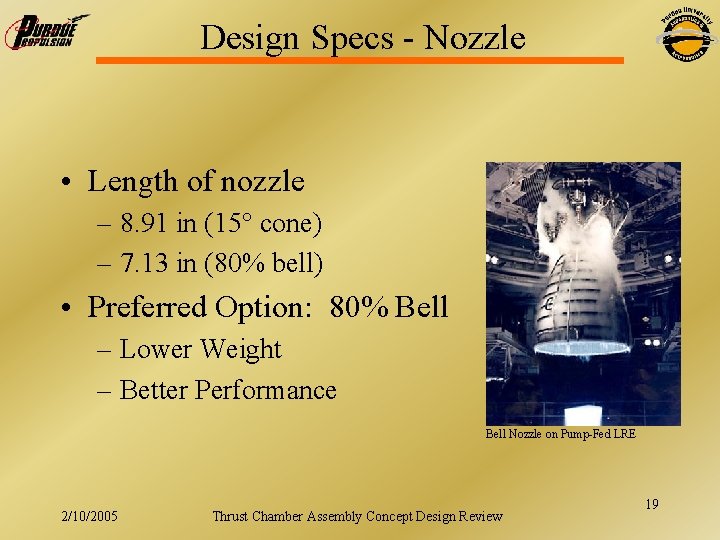
Design Specs - Nozzle • Length of nozzle – 8. 91 in (15° cone) – 7. 13 in (80% bell) • Preferred Option: 80% Bell – Lower Weight – Better Performance Bell Nozzle on Pump-Fed LRE 2/10/2005 Thrust Chamber Assembly Concept Design Review 19
Design Requirements - Injector • • By far the most complicated part of design ΔP = 70 psi Shouldn’t melt or scorch Provide combustion stability No inter-propellant seals Total flow rate = 8. 51 lbm/s Ox flow rate = 6. 21 lbm/s Fuel Flow rate = 2. 3 lbm/s 2/10/2005 Thrust Chamber Assembly Concept Design Review 20
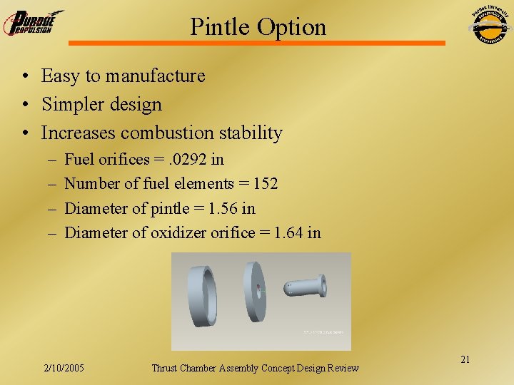
Pintle Option • Easy to manufacture • Simpler design • Increases combustion stability – – Fuel orifices =. 0292 in Number of fuel elements = 152 Diameter of pintle = 1. 56 in Diameter of oxidizer orifice = 1. 64 in 2/10/2005 Thrust Chamber Assembly Concept Design Review 21
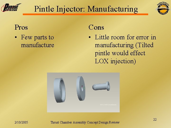
Pintle Injector: Manufacturing Pros Cons • Few parts to manufacture • Little room for error in manufacturing (Tilted pintle would effect LOX injection) 2/10/2005 Thrust Chamber Assembly Concept Design Review 22
Flat Face Injector • • More traditional option/better known Better performance O/F biasing against wall Harder to manufacture (hole sizes are small and numerous) – Fuel orifice size =. 0319 in – Number of elements = 128 – Ox orifice size =. 0320 in – Number of elements = 256 2/10/2005 Thrust Chamber Assembly Concept Design Review 23
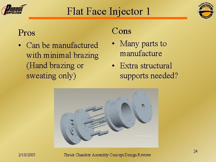
Flat Face Injector 1 Pros Cons • Can be manufactured with minimal brazing (Hand brazing or sweating only) • Many parts to manufacture • Extra structural supports needed? 2/10/2005 Thrust Chamber Assembly Concept Design Review 24
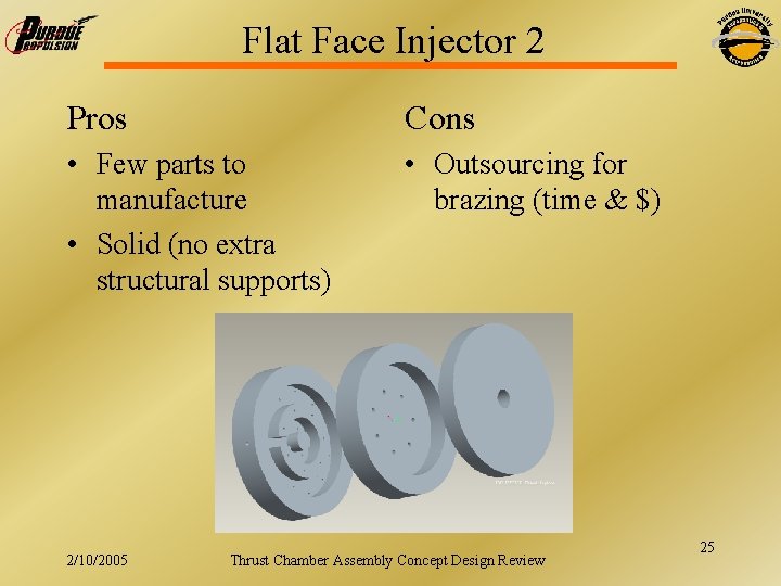
Flat Face Injector 2 Pros Cons • Few parts to manufacture • Solid (no extra structural supports) • Outsourcing for brazing (time & $) 2/10/2005 Thrust Chamber Assembly Concept Design Review 25
Injector Selection Criteria • Wants: – Large knowledge base – Low-cost design – Easily manufactured – Meet performance requirements – Stable combustion 2/10/2005 Thrust Chamber Assembly Concept Design Review 26
Materials Compatibility • LOX is highly corrosive, need resistive materials • High Resistance – Copper, Nickel alloys, and coppernickel alloys • Medium Resistance – Stainless steels, aluminum alloys • Low Resistance – Carbon steel, iron 2/10/2005 Thrust Chamber Assembly Concept Design Review 27
Materials • Monel (Copper-Nickel Alloys) – High flame resistance (up to 10, 000 psi) – High strength to weight ratio • Inconel (Nickel Alloys) – High flame resistance (up to 10, 000 psi) – High strength 2/10/2005 Thrust Chamber Assembly Concept Design Review 28
Materials • Copper – High flame resistance (up to 8000 psi) – Cheap • Stainless Steel – Medium flame resistance (304 up to 1000 psi, 316 up to 500 psi) – Good structural properties – Cheap 2/10/2005 Thrust Chamber Assembly Concept Design Review 29
Preliminary Material Choices • Copper or Stainless Steel for Lox components – Budget Constraints – Manufacturability • Nickel plating for injector face heat management if necessary 2/10/2005 Thrust Chamber Assembly Concept Design Review 30
Lox Seals • All seals should be “Hard Seals” – Metal-on-metal contact • Pure Teflon ® – One of a few materials that can be used for sealing components together if a hard seal is not possible – Must be many layers for a robust seal to allow for thermal contraction 2/10/2005 Thrust Chamber Assembly Concept Design Review 31
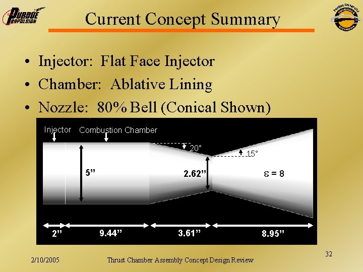
Current Concept Summary • Injector: Flat Face Injector • Chamber: Ablative Lining • Nozzle: 80% Bell (Conical Shown) Injector Combustion Chamber 20° 5” 2” 2/10/2005 15° 2. 62” 9. 44” 3. 61” Thrust Chamber Assembly Concept Design Review =8 8. 95” 32
Applicability to SLV • Engine could be used on a Purdue-designed rocket. • Engine could be modified or scaled to suit the specific needs of the project. • Design process could be followed for a new engine. 2/10/2005 Thrust Chamber Assembly Concept Design Review 33
Near Future Steps • • Injector Iterations Heat Transfer / Thermal Analysis Material Selection Structural Analysis Interface Design Nozzle Design Failure Mode Analysis 2/10/2005 Thrust Chamber Assembly Concept Design Review 34
¿Questions? 2/10/2005 Thrust Chamber Assembly Concept Design Review 35
Appendix • Documentation Control • Additional Design Guidelines 2/10/2005 Thrust Chamber Assembly Concept Design Review 36
Documentation Control • Documentation Control – Anyone can post a file they deem useful, using the file format. – The Designers have sole access to editing any drawing files. • File Format: – component_mmdd_ver. ext • File Deletion – Old files are to be moved to the "OLD" directory for at least one week before they are deleted. – Only the Designers or the Project Manager can delete any file, which shall occur at regular intervals to clear out any unnecessary files. 2/10/2005 Thrust Chamber Assembly Concept Design Review 37
Specified Design Guidelines Prospector 7 is a modified version of Prospector 5 Thrust: 2, 200 lbf; GLOW: 550 lbm 6 fully loaded tanks of each propellant: 246 lbm Burnout altitude: 10, 000 ft; Coast: 30, 000 – 40, 000 ft • Engine Design Guidelines: • @ O/F: 2. 27 Propylene and LOX will deplete at about the same rate • Mass: 15 lbm • Burntime: 20 seconds • Injector: flat head designs due to higher performance potential and easier control of temperatures • Tank Pressure: 450 psi; Injector Pressure Loss: 70 psi • Chamber Design: Ablative chambers, with some including graphite throat inserts Silica tape from Cotronics and an epoxy from a NASA TPS • L*: 1 meter • C*eff: 0. 95 (if possible) 2/10/2005 Thrust Chamber Assembly Concept Design Review 38
Design Objectives • Design a liquid propellant thrust chamber assembly to be launched as a flight demonstration engine for Cal. State Long Beach. • Design with the constraint that hardware must be designed and built using Purdue facilities and personnel • Cost? ? • Adam – feel free to add stuff here 2/10/2005 Thrust Chamber Assembly Concept Design Review 39
Design Objectives Level 2 • • • Thrust ~ 2200 lbf (Sea Level) Chamber Pressure ~ 300 psi Propellants: LOX-propylene Mixture ratio (O/F) = 2. 27 Burn time ~ 15 s Engine mass ~ 15 lbm 2/10/2005 Thrust Chamber Assembly Concept Design Review 40
- Slides: 40