Link Analysis CN Uplink Uplink Carrier to Noise
 (C/N)u = (EIRP)e-(Path Loss)u+(G/T)sat-K-Noise BW")
 - Is the performance criterion for")

 –Why is it used? - To represent the amount of")


 is another choice when")


- Slides: 30
Link Analysis C/N Uplink (Uplink Carrier to Noise Ratio) (C/N)u = (EIRP)e-(Path Loss)u+(G/T)sat-K-Noise BW [d. B] C/N Downlink (C/N)d = (EIRP)sat-(Path Loss)d+(G/T)e-K-Noise BW [d. B]
Eb/No (Energy per bit per Noise Power Density) - Is the performance criterion for any desired BER - It is the measure at the input of the receiver - Is used as the basic measure of how strong the signal is - Directly related to the amount of power transmitted from the uplink station Eb/No = (C/N)T + Noise BW - Information Rate
Carrier Parameters • Solution - Carrier Performance: - Eb/No Threshold - Bit Error Rate (BER) - Rain Attenuation
Bit Error Rate (BER) –Why is it used? - To represent the amount of errors occurring in a transmission - To express the link quality -What is it? - BER is an equipment characteristic - BER is directly related to Eb/No - BER improves as the Eb/No gets larger P = 1/2 e -Eb/No (with P = Probability of error)
Carrier Parameters • Performance: -Application specific • Digital voice links: -BER threshold 10 • Data links: - BER threshold: 10 -4 -3
Carrier Parameters • Performance: -Typical Eb/No values for different FEC Eb/No for FEC 1/2 (d. B) FEC 3/4 (d. B) FEC 7/8 (d. B) 6. 5 7. 1 7. 6 9. 9 8. 0 8. 7 9. 2 11. 0 9. 1 9. 7 10. 4 12. 1 BER 10 -6 10 -7 10 -8 10 -10
Rain Attenuation • Performance - Rain Attenuation: - Availability • Rain Margins - Typically 99. 60 % for Ku-Band - Typically 99. 96 % for C-Band E/S • Performance - Additional Margins: - Adjacent Satellite Interference (ASI) - Interference Margins
Polarization
Contents • Polarization • Types of Polarization • Antenna polarization • Manual Polarization Switching • Polarization of satellite signals • Depolarization • Cross polarization discrimination • Ionospheric depolarization, rain & ice depolarization • XPD and Co-Polar Attenuation • Ionospheric Effect
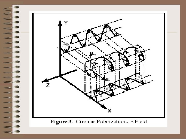
Polarization • The polarization of an electromagnetic wave is defined as the orientation of the electric field vector. Recall that the electric field vector is perpendicular to both the direction of travel and the magnetic field vector.
Cont… • Polarization is also described as the "direction of vibration" on the radio wave. • It depends on the orientation of elements of an antenna, when you set elements vertical, it generates verticalpolarized radio wave similarly when you set as horizontal, it generates horizontal-polarized. • In the case of YAGI antenna, the direction of Electronic-Field is same as the direction of its elements. • Radio stations have to set the same direction of polarization to communicate each other.
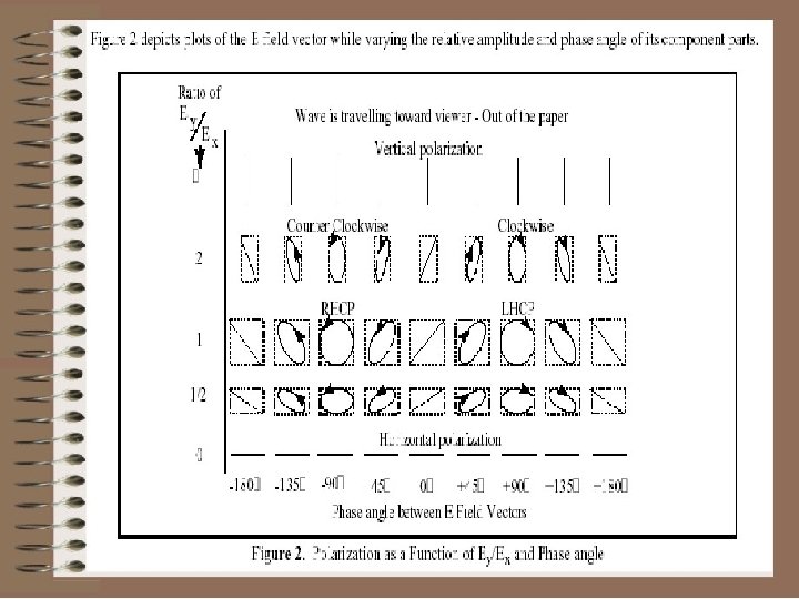
Types of Polarization • An electromagnetic wave is frequently composed of (or can be broken down into) two orthogonal parts. This may be due to the arrangement of power input leads to various points on a flat antenna, or due to an interaction of active elements in an array, or many other reasons. • The geometric figure traced by the sum of the electric field vectors over time is, in general, an ellipse. Under certain conditions the ellipse may collapse into a straight line, in which case the polarization is called linear.
Cont… • In the other extreme, when the two components are of equal magnitude and 900 out of phase, the ellipse will become circular. Thus; linear and circular polarization are the two special cases of elliptical polarization. Linear polarization may be further classified as being vertical, horizontal, or slant.
Polarization and its types
Cont… • Polarization makes the beam more concentrated • FSS satellites use horizontal and vertical polarization, whereas DBS (direct boroadcast sat. ) satellites use left- and right-hand circular polarization • To use the channels that are available for satellite broadcast as efficiently as possible, both horizontal and vertical polarization (and left- and right-hand circular polarization) can be applied simultaneously per channel or frequency. In such cases the frequency of one of the two is slightly altered, to prevent possible interference
Cont… • Horizontal and vertical transmissions will therefore not interfere with each other because they are differently polarized. This means twice as many programs can be transmitted per satellite • Consequently, via one and (almost) the same frequency the satellite can broadcast both a horizontal and a vertical polarized signal (H and V), or a left- and right-hand circular polarized signal (LH and RH).
Radio stations have to set with same direction of polarization to communicate each other. • When you try to hear the vertical-polarized wave with horizontal- polarized antenna, what will be happened? A theory tells it is impossible to receive. In fact, although it is possible, It becomes very difficult (very weak less than -20 d. B ). This is due to: - The radio waves do not travel with pure-polarized condition, and - There is no real antenna that has pure-polarized character. Anyway, you should adjust the polarization for better communication.
Is Circular Polarization better choice for satellite? • Circular-polarization (CP) is another choice when you could not decide the polarization of your choice. • CP is the special style of polarization, the direction of Electric-Field rotates one times per one cycle. • The CP antenna can receive both horizontal and vertical polarized radio wave, even in the direction of slant-polarized. • CP is very popular technique for satellite communication in both commercial and amateur satellite systems.
Antenna Polarization • Table 1 shows theoretical ratio of power transmitted between antennas of different polarization. These ratios are seldom fully achieved due to effects such as reflection, refraction, and other wave interactions, so some practical ratios are also included.
Cont…
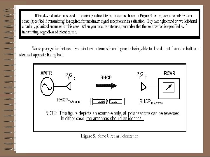
Cont… • The sense of antenna polarization is defined from a viewer positioned behind an antenna looking in the direction of propagation. The polarization is specified as a transmitting, not receiving antenna regardless of intended use. • We frequently use "hand rules" to describe the sense of polarization. The sense is defined by which hand would be used in order to point that thumb in the direction of propagation and point the fingers of the same hand in the direction of rotation of the E field vector.
Cont… • For example, referring to Figure 4, if your thumb is pointed in the direction of propagation and the rotation is counterclockwise looking in the direction of travel, then you have left hand circular polarization. • The polarization of a linearly polarized horn antenna can be directly determined by the orientation of the feed probe, which is in the direction of the E-field.
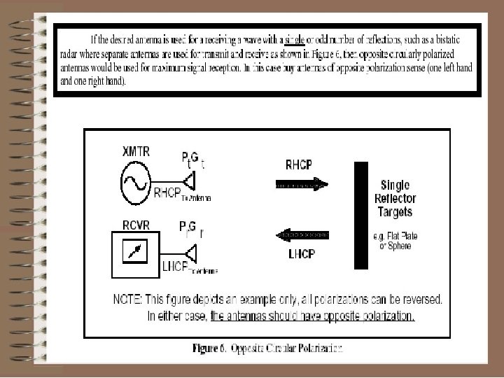
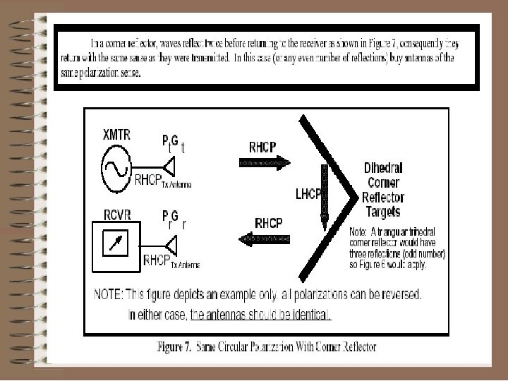
Cont… • In general, a flat surface or sphere will reflect a linearly polarized wave with the same polarization as received. A horizontally polarized wave may get extended range because of water and land surface reflections, but signal cancellation will probably result in "holes" in coverage. Reflections will reverse the sense of circular polarization.
Cont… • For a linearly polarized antenna, the radiation pattern is taken both for a co-polarized and cross polarized response. • The polarization quality is expressed by the ratio of these two responses. The ratio between the responses must typically be great (30 d. B or greater) for an application such as cross polarized jamming • For general applications, the ratio indicates system power loss due to polarization mismatch. • For circularly polarized antennas, radiation patterns are usually taken with a rotating linearly polarized reference antenna.