
LINAC 4 Quadrupole Power Converters TEEPC J M





- Slides: 11
LINAC 4 Quadrupole Power Converters TE-EPC J. M. CRAVERO 06. 10. 2009 1
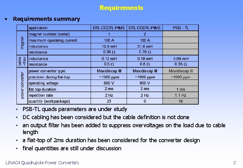
Requirements • Requirements summary • PSB-TL quads parameters are under study • DC cabling has been considered but the cable definition is not done • an output filter has been added to suppress overvoltages on the load due to cable length • a flat-top of 2 ms duration has been considered for the converter design • final quantities are still under discussion LINAC 4 Quadrupole Power Converters 2
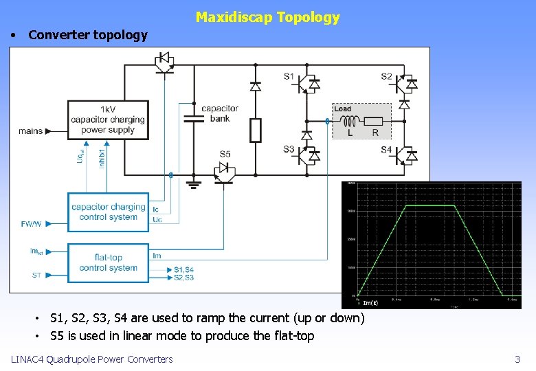
Maxidiscap Topology • Converter topology • S 1, S 2, S 3, S 4 are used to ramp the current (up or down) • S 5 is used in linear mode to produce the flat-top LINAC 4 Quadrupole Power Converters 3
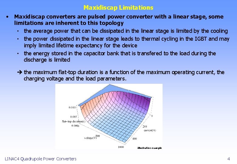
Maxidiscap Limitations • Maxidiscap converters are pulsed power converter with a linear stage, some limitations are inherent to this topology • the average power that can be dissipated in the linear stage is limited by the cooling • the power dissipated in the linear stage leads to thermal cycling in the IGBT and may imply limited lifetime expectancy for the device • the energy stored in the capacitor bank that is transfered to the load during the discharge is limited the maximum flat-top duration is a function of the maximum operating current, the charging voltage and the load parameters. illustrative example LINAC 4 Quadrupole Power Converters 4
Simulations, junction temperature and expected lifetime • DTL-CCDTL-PIMS quadrupoles : waveforms with 2 ms flat-top • green load = 1 magnet – Uc=600 V • red load = 2 magnets serially connected – Uc=900 V LINAC 4 Quadrupole Power Converters 5
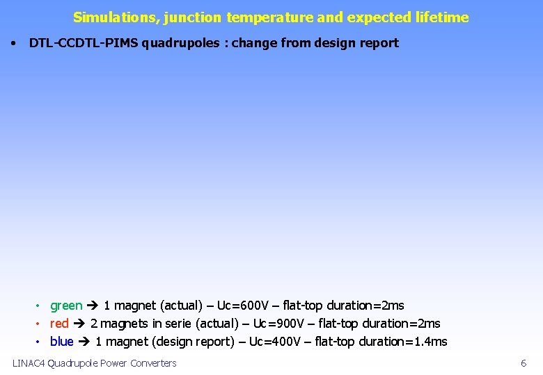
Simulations, junction temperature and expected lifetime • DTL-CCDTL-PIMS quadrupoles : change from design report • green 1 magnet (actual) – Uc=600 V – flat-top duration=2 ms • red 2 magnets in serie (actual) – Uc=900 V – flat-top duration=2 ms • blue 1 magnet (design report) – Uc=400 V – flat-top duration=1. 4 ms LINAC 4 Quadrupole Power Converters 6
IGBT junction temperature and expected lifetime • DTL-CCDTL-PIMS: IGBT junction temperature • green (1 magnet – 2 ms flat-top) Tj = 6° - Max. Tj= 41° • red (2 magnets – 2 ms flat-top) Tj = 10° - Max. Tj= 49° with such values, thermal cycling has not effect on lifetime expectancy LINAC 4 Quadrupole Power Converters 7
Technical Design Summary • RMS values are compatible with magnet design • TL quads : the goal is to use the same converter design for both magnets parameters LINAC 4 Quadrupole Power Converters 8
Power Converter Modifications • Same converters have been used in Linac II, Linac III and LEIR but some modifications are necessary to allow flat-top with extended duration • Power crate - the capacitor bank has to be increased to 1000 u. F - capacitor charger replacement have to be studied - some modifications have to be foreseen (cabling, IGBT driver , etc. . . ) - test with filter, cables and dummy load have to be performed - compatibility with previous versions must be kept • Electronic crate - FGC 3 integration - flat-top control with anti-windup system has to be evaluated Electronic crate Power crate LINAC 4 Quadrupole Power Converters 9
Basic Planning • • Technical design must be finished before the end of 2009, TL quads parameters have to be defined urgently. Final converter quantities are not needed before mid-2010 LINAC 4 Quadrupole Power Converters 10
Conclusion • With the latest LINAC 4 EM Quad design, it is possible to power 1 or 2 magnets in series by limiting the di/dt during the ramp • The PSB transfer line Quads and LINAC 4 Quads will use the same power converter design final converter design will be done when the PSB transfer line magnet design is well advanced • Development and test of the Quadrupole Power Converter prototype will start early 2010, with series production in 2011 final quantities are required before tendering in mid-2010 LINAC 4 Quadrupole Power Converters 11