
LIGOG 1000642 V 1 Technologies of Gravitational Wave
- Slides: 42
LIGO-G 1000642 -V 1 Technologies of Gravitational Wave Detection Koji Arai – LIGO Laboratory / Caltech
Background / Overview �Introduce common technologies / terminologies �Brief review of GW / GW detection �Interferometer GW detectors �Interferometry �Sensing & Control
Interferometer GW detection
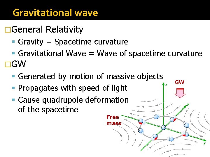
Gravitational wave �General Relativity Gravity = Spacetime curvature Gravitational Wave = Wave of spacetime curvature �GW Generated by motion of massive objects Propagates with speed of light Cause quadrupole deformation of the spacetime Free mass GW
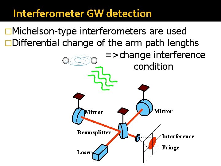
Interferometer GW detection �Michelson-type interferometers are used �Differential change of the arm path lengths =>change interference condition Mirror Beamsplitter Laser Mirror Interference Fringe
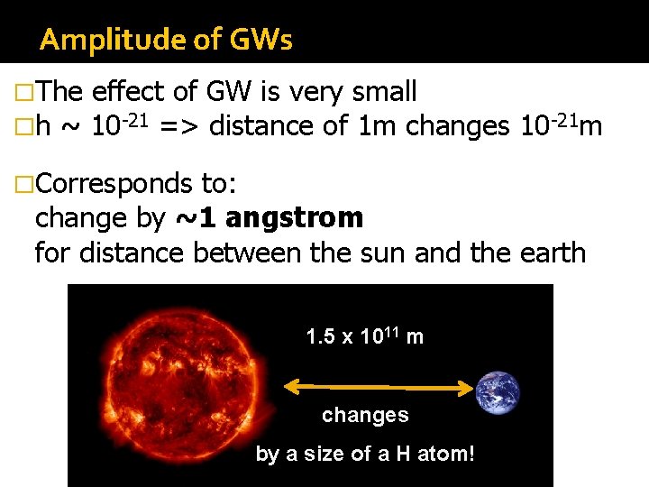
Amplitude of GWs �The effect of GW is very small �h ~ 10 -21 => distance of 1 m changes �Corresponds 10 -21 m to: change by ~1 angstrom for distance between the sun and the earth 1. 5 x 10¹¹ m changes by a size of a H atom!
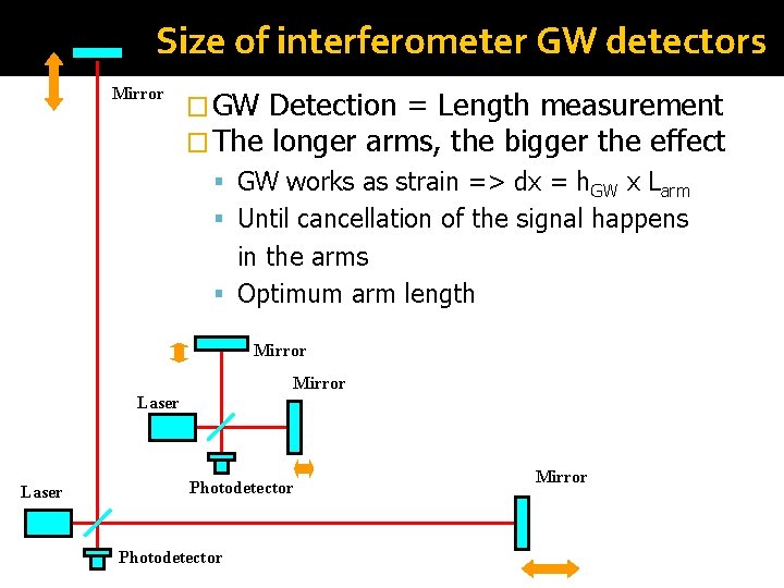
Size of interferometer GW detectors Mirror � GW Detection = Length measurement � The longer arms, the bigger the effect GW works as strain => dx = h. GW x Larm Until cancellation of the signal happens in the arms Optimum arm length Mirror Laser Photodetector Mirror
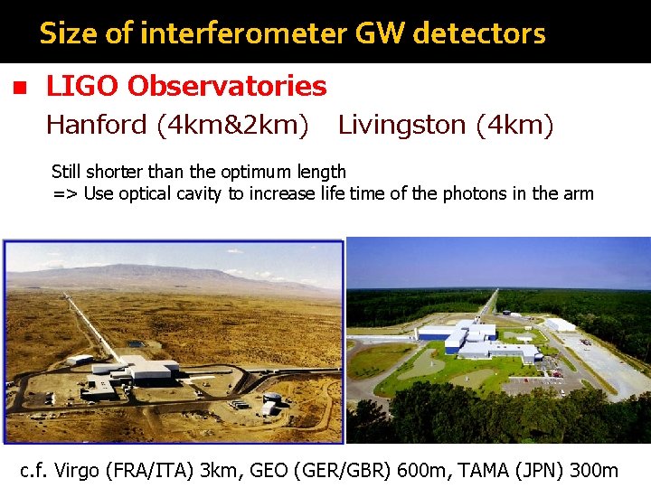
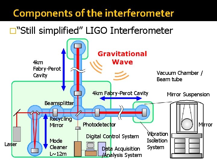
Size of interferometer GW detectors n LIGO Observatories Hanford (4 km&2 km) Livingston (4 km) Still shorter than the optimum length => Use optical cavity to increase life time of the photons in the arm c. f. Virgo (FRA/ITA) 3 km, GEO (GER/GBR) 600 m, TAMA (JPN) 300 m
Components of the interferometer �“Still simplified” LIGO Interferometer 4 km Fabry-Perot Cavity Vacuum Chamber / Beam tube 4 km Fabry-Perot Cavity Mirror Suspension Beamsplitter Recycling Mirror Laser Mode Cleaner L~12 m Mirror Photodetector Digital Control System Data Acquisition /Analysis System Vibration Isolation System
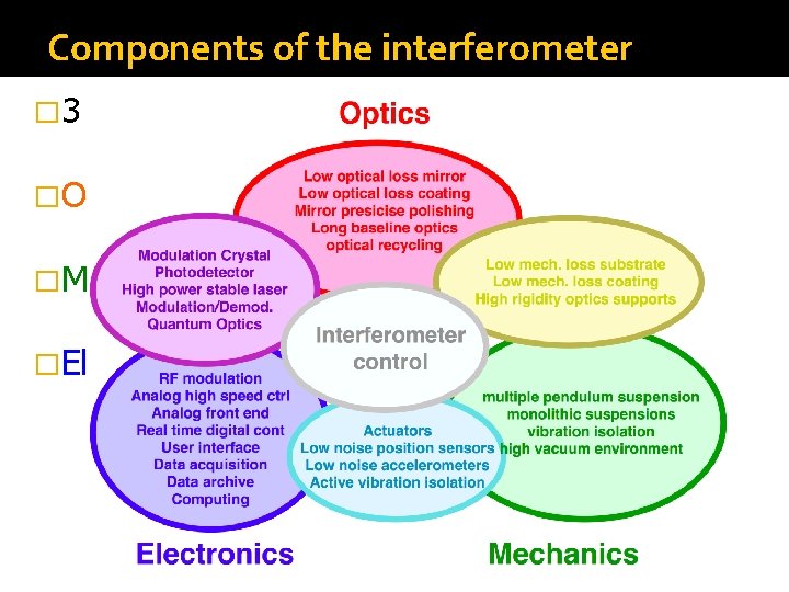
Components of the interferometer � 3 fundamentals of the GW detector �Optics �Mechanics �Electronics
What can we do for the detection? � An IFO produces a continuous signal in the GW channel � The detector is fixed on the ground => can not be directed to a specific angle � GWs and noises are, in principle, indistinguishable => Anything we detect is GW � Reduce noises! � Obs. distance is inv-proportional to noise level � x 10 better => x 10 farther => x 1000 more galaxies
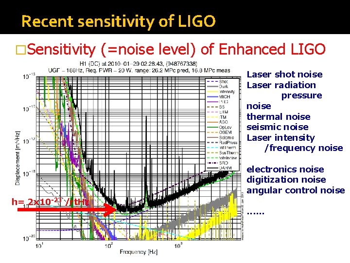
Recent sensitivity of LIGO �Sensitivity (=noise level) of Enhanced LIGO Laser shot noise Laser radiation pressure noise thermal noise seismic noise Laser intensity /frequency noise h= 2 x 10 -23 /rt. Hz electronics noise digitization noise angular control noise. . .
Summary �GWs ~ ripples of the spacetime �Not yet directly detected ~ the effect is so small (h<10 -21) �Michelson-type interferometers are used �GW detection is a precise length (=displacement) measurement! �GW effect is very small
Summary �Essentially, the larger, the better. LIGO has two largest interferometers in the world �IFO consists of many components Optics / Mechanics / Electronics and their combinations (e. g. Opto-Electronics) �noise and signal are, in principle, indistinguishable. Noise reduction is the matter.
Interferometry
Laser interferometry � GW detection = High sensitive detection of displacement � Laser interferometry is an indispensable technology (lambda ~ 1 um) � We use optical cavities in many places What is an optical cavity?
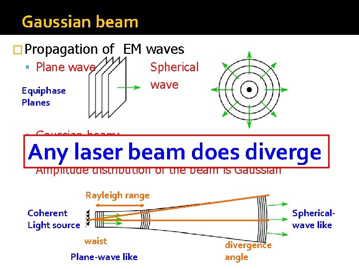
Gaussian beam � Propagation of EM waves Plane wave Equiphase Planes Spherical wave Gaussian beam: A solution to paraxial approximated wave equation Any laser beam does diverge Amplitude distribution of the beam is Gaussian Rayleigh range Coherent Light source Sphericalwave like waist Plane-wave like divergence angle
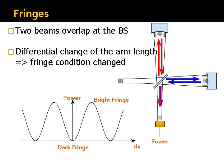
Fringes � Two beams overlap at the BS � Differential change of the arm length => fringe condition changed Power Dark Fringe Bright Fringe dx Power
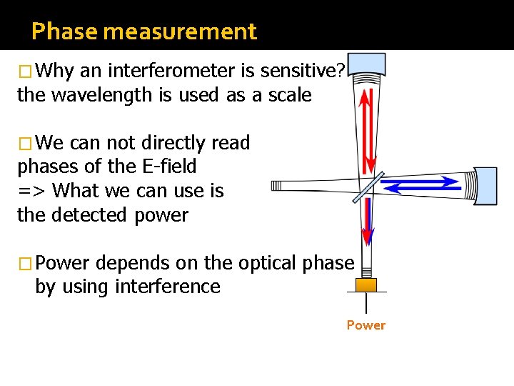
Phase measurement � Why an interferometer is sensitive? the wavelength is used as a scale � We can not directly read phases of the E-field => What we can use is the detected power � Power depends on the optical phase by using interference Power
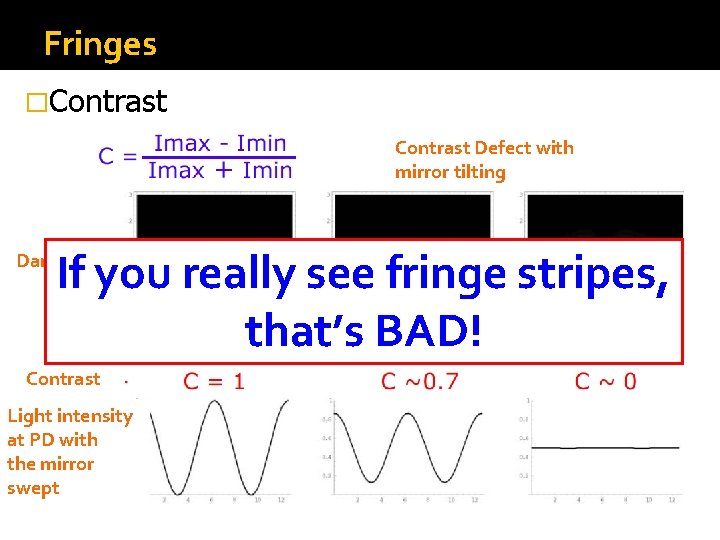
Fringes �Contrast Defect with mirror tilting If you really see fringe stripes, that’s BAD! Dark Fringe Contrast Light intensity at PD with the mirror swept
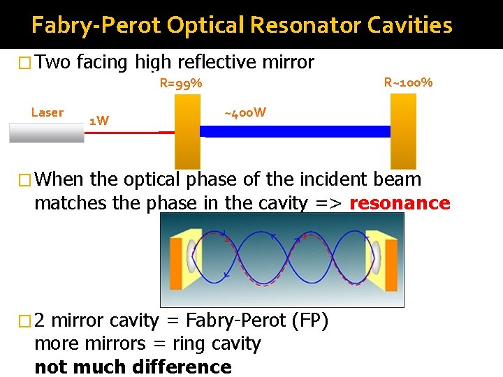
Fabry-Perot Optical Resonator Cavities � Two facing high reflective mirror R~100% R=99% Laser 1 W ~400 W � When the optical phase of the incident beam matches the phase in the cavity => resonance � 2 mirror cavity = Fabry-Perot (FP) more mirrors = ring cavity not much difference
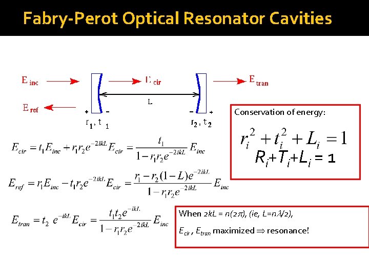
Fabry-Perot Optical Resonator Cavities Conservation of energy: Ri+Ti+Li = 1 When 2 k. L = n(2 p), (ie, L=nl/2), Ecir , Etran maximized resonance!
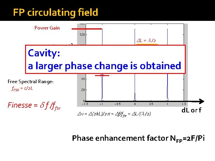
FP circulating field Power Gain DL = l /2 Cavity: D f = c/2 L a larger phase change is obtained df fsr Free Spectral Range: f. FSR = c/2 L Finesse = d f /ffsr Dn = D(2 k. L)/2 p = Df/ffsr = DL/(l /2) d. L or f Phase enhancement factor NFP=2 F/Pi
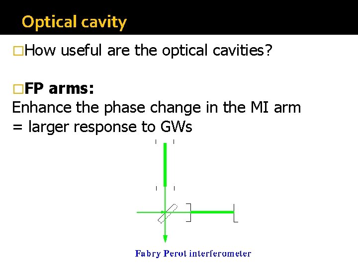
Optical cavity �How �FP useful are the optical cavities? arms: Enhance the phase change in the MI arm = larger response to GWs
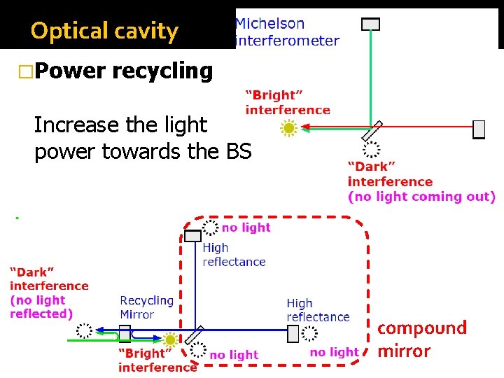
Optical cavity �Power recycling Increase the light power towards the BS compound mirror
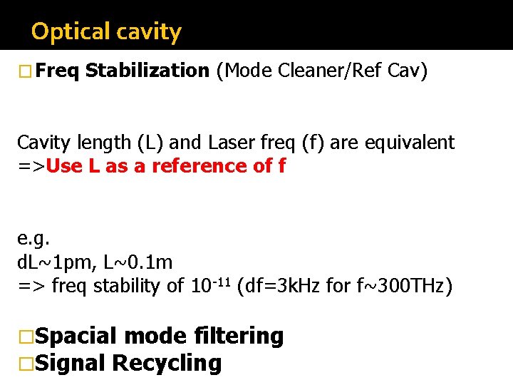
Optical cavity � Freq Stabilization (Mode Cleaner/Ref Cav) Cavity length (L) and Laser freq (f) are equivalent =>Use L as a reference of f e. g. d. L~1 pm, L~0. 1 m => freq stability of 10 -11 (df=3 k. Hz for f~300 THz) �Spacial mode filtering �Signal Recycling
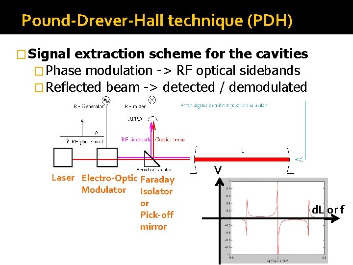
Pound-Drever-Hall technique (PDH) � Signal extraction scheme for the cavities � Phase modulation -> RF optical sidebands � Reflected beam -> detected / demodulated Laser Electro-Optic Faraday Modulator Isolator or Pick-off mirror V d. L or f
Summary �Interferometer is a sensitive device Because we are reading the phase of the light �Optical cavity is more sensitive Because the phase change is enhanced by the cavity �Optical �The cavities are useful! PDH technique
Sensing & Control
Sensing and Control � Feedback controls are a common technique in the instruments and measurements � For high sensitivity, we use interferometry. The response of the interferometers are nonlinear Michelson: moderately Fabry-Perot: highly nonlinear � Presence of seismic disturbance We need to control the mirror positions
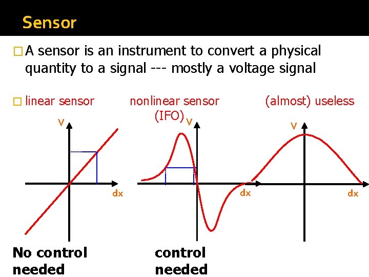
Sensor �A sensor is an instrument to convert a physical quantity to a signal --- mostly a voltage signal � linear sensor nonlinear sensor (IFO) V V V dx dx No control needed (almost) useless control needed dx
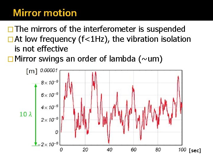
Mirror motion � The mirrors of the interferometer is suspended � At low frequency (f<1 Hz), the vibration isolation is not effective � Mirror swings an order of lambda (~um) [sec]
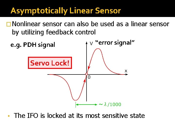
Asymptotically Linear Sensor � Nonlinear sensor can also be used as a linear sensor by utilizing feedback control e. g. PDH signal “error signal” Servo Lock! • The IFO is locked at its most sensitive state
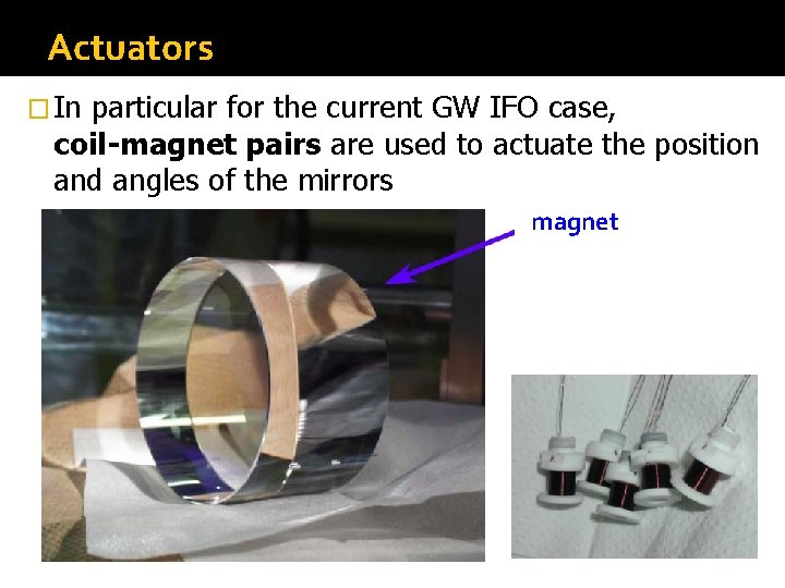
Actuators � In particular for the current GW IFO case, coil-magnet pairs are used to actuate the position and angles of the mirrors magnet
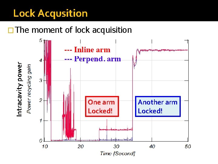
Lock Acqusition Intracavity power � The moment of lock acquisition One arm Locked! Another arm Locked!
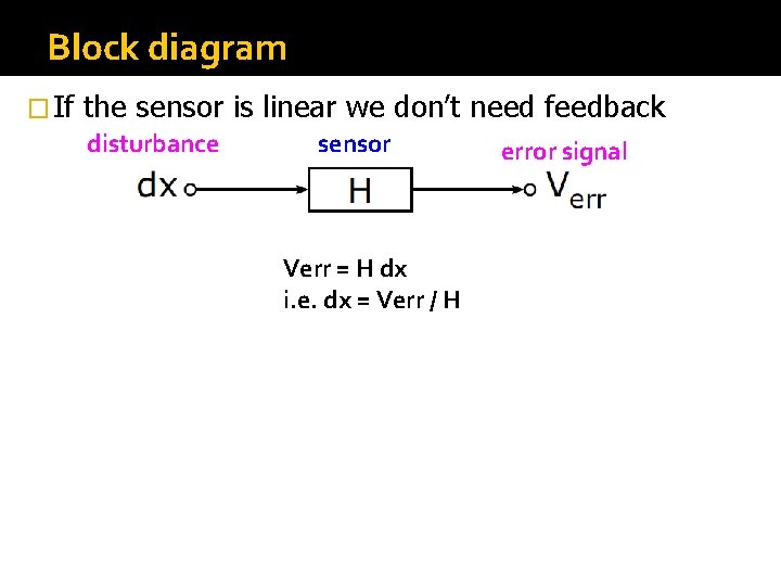
Block diagram � If the sensor is linear we don’t need feedback disturbance sensor Verr = H dx i. e. dx = Verr / H error signal
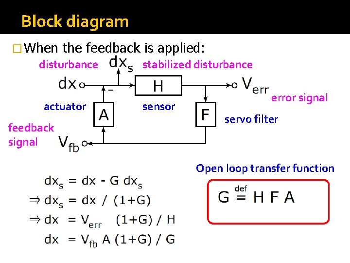
Block diagram � When the feedback is applied: disturbance stabilized disturbance actuator feedback signal sensor error signal servo filter Open loop transfer function
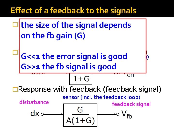
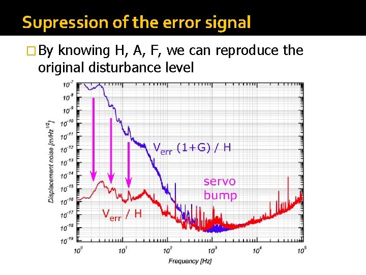
Effect of a feedback to the signals �Linear sensor the size of the signal depends disturbance sensor on the fb gain (G) error signal �Response with feedback (error signal) �Response with feedback (feedback signal) (incl. is thegood feedback loop) G<<1 the errorsensor signal disturbance error signal G>>1 the fb signal is good disturbance sensor (incl. the feedback loop) feedback signal
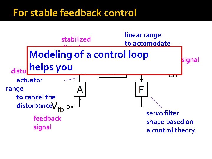
For stable feedback control linear range stabilized to accomodate disturbance residual dxs Modeling of a control loop error signal helps you disturbance actuator range to cancel the disturbance feedback signal servo filter shape based on a control theory
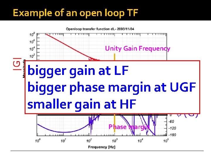
Example of an open loop TF Unity Gain Frequency bigger gain at LF bigger phase margin at UGF smaller gain at HF Phase margin
Supression of the error signal � By knowing H, A, F, we can reproduce the original disturbance level
Summary �With feedback control, we can treat a nonlinear system as a linear system �Feedback control is the key for GW interferometers to keep their performance �An openloop transfer function is to be designed in each case. �Feedback control changes the signals from the system. Modeling always helps to understand how the original signals are.