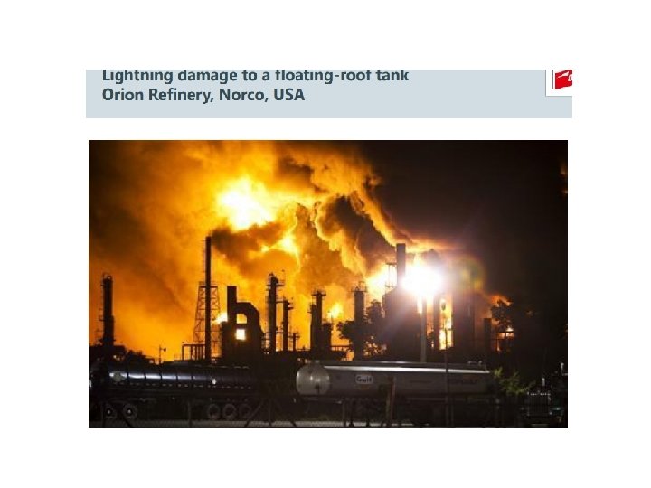
Lightning Protection For centuries lightning strikes have caused


; 2.")


- Slides: 29
Lightning Protection • For centuries, lightning strikes have caused serious damage and fires to buildings and other structures, and have also killed the occupants of buildings that were struck. • Protection of structures from the effects of lightning strikes is more precise today than it was in 1752 at the time of the experiments and the original invention of lightning protection by Benjamin Franklin.
• The original lightning protection system of that era included a number of metal rods attached to the walls and roof of a building. • These rods were connected by copper wire, which was connected to metal rods driven 10 feet into the ground. When lightning struck, it usually struck a rod and its energy was transferred to the ground by the lightning rods, cables, and ground rods. • The alternative to this is that energy being transferred to high-impedance or nonconductive building materials.
• NFPA 780: Lightning Protection System. "A complete system of strike termination devices, conductors, grounding electrodes, interconnecting conductors, surge protective devices, and other connectors and fittings required to complete the system. “ • The basic principle in protecting life and property from lightning is to provide a path by which the electrical energy can enter or leave the earth without damaging the structure. • The low-impedance path provided by metal rods, cables, and grounding electrodes is ideal for this purpose, provided that the path is continuous from the grounding electrode to the terminal on the building.
• Elevated air terminals - provide the protection required, provided that they are located systematically and as required by NFPA 780. These air terminals provide protection for the area spread out below them, called a "zone of protection. " • These air terminals are designed to be mounted to different types of surfaces (photos 1 and 2) and to different types of materials using connectors that will not be corrosive either to the material of the air terminal or to the material to which it is attached.
Figure : Photo shows the air terminal at the gable of the greenhouse with the main cable running along the ridge from the left and down the right slope of the gable at the right, toward a down conductor
Figure; Photo shows a down conductor attached to a brick wall and connected to the cable leading to the grounding electrode.
• Air terminals are also used to protect projections above the roof and metallic objects on the roof, like the metal chimney in photo 1. The air terminals are connected to a main conductor cable (photos 1 and 2), which is connected to two or more down conductors (photo 3) each with its own grounding electrode or rod. • A second component of a lightning-protection system is common ground bonding. Chapter 4. 14 of NFPA 780 calls for interconnection, or bonding, of all grounding conductors and buried metallic conductors that could provide a path for lightning currents, to provide a common ground potential. This interconnection includes lightning protection, electric service, communications, antenna systems, and underground metallic piping
• The third component of a lightning-protection system is permanently-installed surge protection for the building's electrical system, communications systems (cable TV, alarm systems, antenna systems, and data cables). • Surge protection must be installed at all electric service entrances; at the entrances of communications systems; and at the point where any of these leave the building to supply another structure with a cable run of more than 100 feet (30 m). • Supplemental surge protection may also be installed at branch circuit panels and at the point of use.
FIGURE - Roof Types: Protection Methods. (Drawings are top and end views of each roof type. )
Air Terminal Height. The tip of an air terminal shall be not less than 254 mm (10 in. ) above the object or area it is to protect, as shown in Figure
FIGURE - Air Terminal Support.
Pressure Systems • The definition of a ‘pressure system’ under the Pressure Systems Regulations is given by (a) a system comprising one or more pressure vessels of rigid construction, any associated pipework and protective devices; (b) the pipework with protective devices to which a transportable gas container is, or is intended to be, connected; or (c) a pipeline and its protective devices; which contains or is liable to contain a relevant fluid, but does not include a transportable gas container. ’
Pressure System Components 1. pressure vessels (reactors, distillation columns, storage drums and vessels); 2. piping system components (pipes, bends, tees, reducers, flanges, valves, nozzles, nipples); 3. means of adding, controlling or removing heat (fired heaters, reboilers, vaporizers, condensers, coolers, heat exchangers generally);
4. means of increasing, controlling or reducing pressure (pumps, compressors, fans, letdown turbines, control valves. 5. means of adding or removing fluids or solids to or from the process system (pumps, compressors, dump valves); 6. measurement and control devices and systems (instrumentation); 7. utilities and services (electricity, steam, water, air)
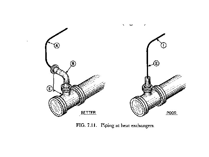
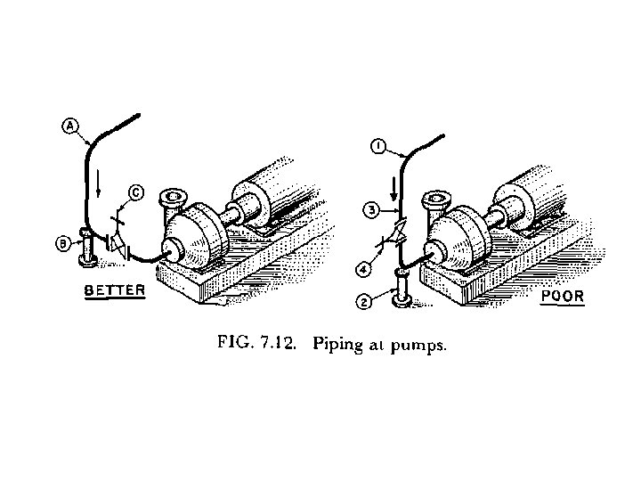
Pipework and Valves • Loss of containment from a pressure system generally occurs not from pressure vessels but from pipework and associated fittings. At least as much attention should be paid to the pipework and fittings as to the vessels. • The plant pipework and fittings include the piping itself, flanges and joints, and fittings, such as the many types of valves, bellows, etc. , together with the pipe supports.
• The cause of the Flixborough disaster was a modification to a 28 in. pipe connection between two reactors. The modification involved the installation of a temporary 20 in. pipe with bellows at each end. • The design of the pipe system was defective in that it did not take into account the bending moments on the pipe due to the pressure in it. The bellows were not installed in accordance with the manufacturer’s instructions. The pipework assembly was not adequately supported.
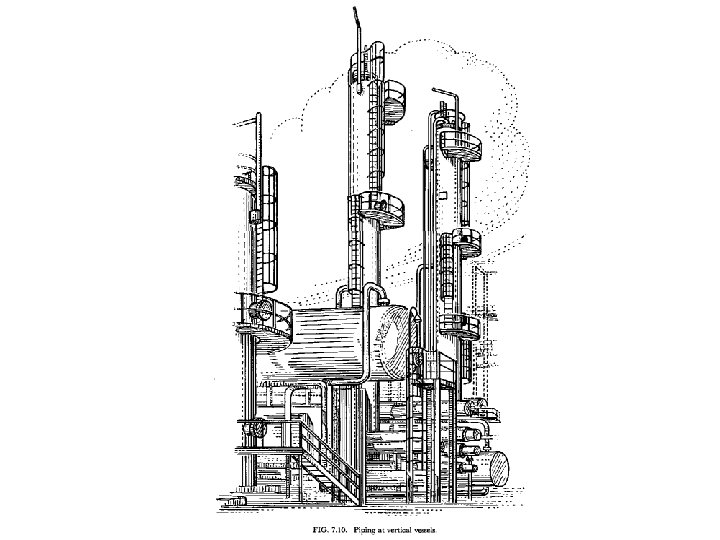
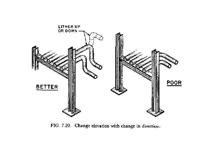
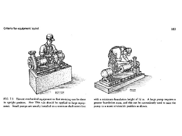
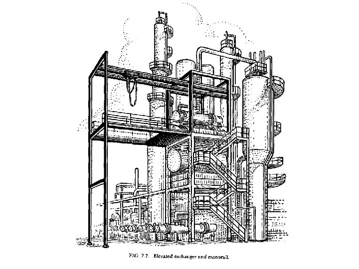
Equipment layout • An experienced piping designer regularly use certain criteria for equipment layout which are generally applicable. They are – Equipment elevations – Maintenance and operating requirements – Process requirements – Layout factors – Horizontal spacing and equipment – Safety – construction
Vessels layout • Vertical vessel • Horizontal vessel