
LIGHT TREE Optical Multicasting for Interactive Realtime Application

![Light-Forest Construct Algorithm � Step 3: For i= 2 to |D] do � Begin](https://slidetodoc.com/presentation_image/5549a2f3ee53b708b9c89615ec0cc77a/image-16.jpg "Light-Forest Construct Algorithm � Step 3: For i= 2 to |D] do � Begin")

- Slides: 27
LIGHT TREE Optical Multicasting for Interactive Real-time Application in Sparse Splitting Optical Networks
CONTENTS ü INTRODUCTION ü LIGHT PATH ü WDM NETWORK ü LIGHT TREE ü SYSTEM MODELS ü GENETIC ALGORITHM for WDM MULTICAST PROBLEM ü CONSTRAINED OPTICAL MULTICAST ROUTING ü RELATED WORK ü CONCLUSION & FUTURE WORK
INTRODUCTION � Today, there is a general consensus that, in the near future, wide area networks (WAN)(such as, a nation wide backbone network) will be based on Wavelength Division Multiplexed (WDM) optical networks. � Depending on the underlying physical topology networks can be classified into three generations: � First Generation: these networks do not employ fiber optic technology; instead they employ copper-based or microwave technology. E. g. Ethernet. � Second Generation: these networks use optical fibers for data transmission but switching is performed in electronic domain. E. g. FDDI. � Third Generation: in these networks both data transmission and switching is performed in optical domain. E. g. WDM.
� The network traffic i. e, the messages or the packets transferred over the network can be of three types : : � UNICAST TRAFFIC - Unicast traffic is sent from a single source to a single destination IP address. � BROADCAST TRAFFIC - Broadcast traffic uses a special IP address to send a single stream of data to all of the machines on the local network. A broadcast address typically ends in 255 (for example, 192. 0. 2. 255) or has 255 in all four fields (255. 255). � MULTICAST TRAFFIC - Unlike unicast addresses, when a data stream is sent to one of these addresses, potential recipients of the data can decide whether or not to receive the data. If the user wants the data, the user's machine receives the data stream; if not, the user's machine ignores it.
LIGHT PATH Ø A light path is an all-optical channel, which may be used to carry circuit switched traffic, and it may span multiple fiber links. Ø A light path can create logical (or virtual) neighbors out of nodes that may be geographically far apart from each other Ø A major objective of light path communication is to reduce the number of hops a packet has to traverse Ø Under light path communication, the network employs an equal number of transmitters and receivers because each light path operates on a point-to-point basis.
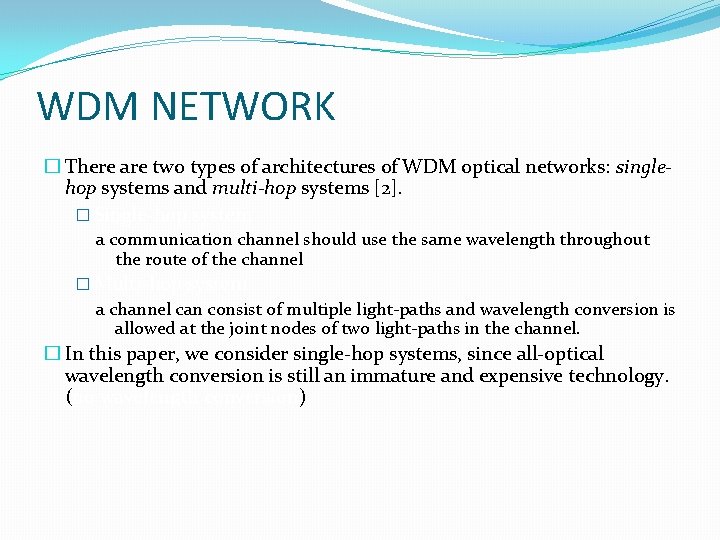
WDM NETWORK � There are two types of architectures of WDM optical networks: singlehop systems and multi-hop systems [2]. � Single-hop system a communication channel should use the same wavelength throughout the route of the channel � Multi-hop system a channel can consist of multiple light-paths and wavelength conversion is allowed at the joint nodes of two light-paths in the channel. � In this paper, we consider single-hop systems, since all-optical wavelength conversion is still an immature and expensive technology. (no wavelength conversion)
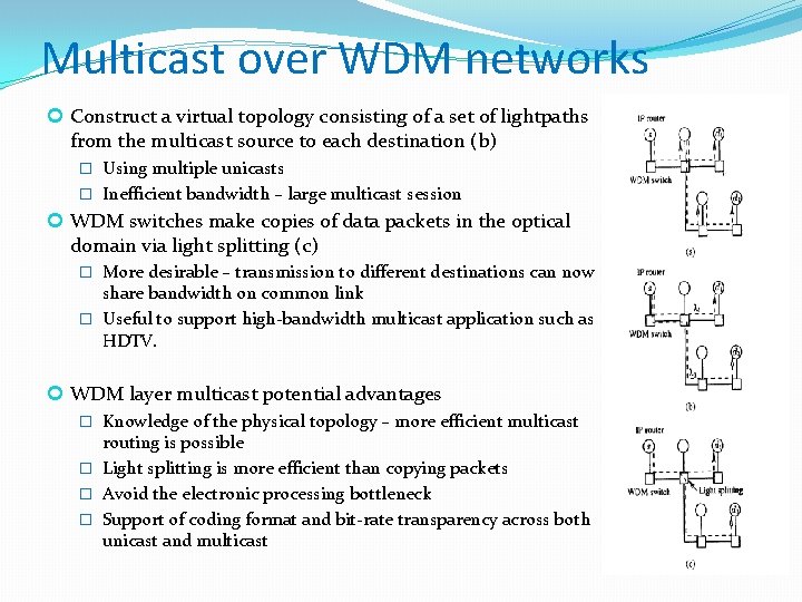
Multicast over WDM networks Construct a virtual topology consisting of a set of lightpaths from the multicast source to each destination (b) � Using multiple unicasts � Inefficient bandwidth – large multicast session WDM switches make copies of data packets in the optical domain via light splitting (c) � More desirable – transmission to different destinations can now share bandwidth on common link � Useful to support high-bandwidth multicast application such as HDTV. WDM layer multicast potential advantages � Knowledge of the physical topology – more efficient multicast routing is possible � Light splitting is more efficient than copying packets � Avoid the electronic processing bottleneck � Support of coding format and bit-rate transparency across both unicast and multicast
LIGHT TREE � A light tree is a point to point multipoint all optical channel, which may span multiple fiber links. � Light tree enables single-hop communication between a source node and a set of destination nodes. � Thus, a light tree based virtual topology can significantly reduce the hop distance, thereby increasing the network throughput.
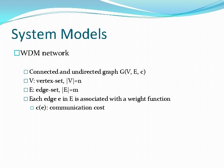
System Models �WDM network � Connected and undirected graph G(V, E, c) � V: vertex-set, |V|=n � E: edge-set, |E|=m � Each edge e in E is associated with a weight function � c(e): communication cost
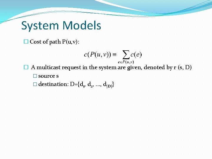
System Models � Cost of path P(u, v): � A multicast request in the system are given, denoted by r (s, D) � source s � destination: D={d 1, d 2, . . . , d|D|}
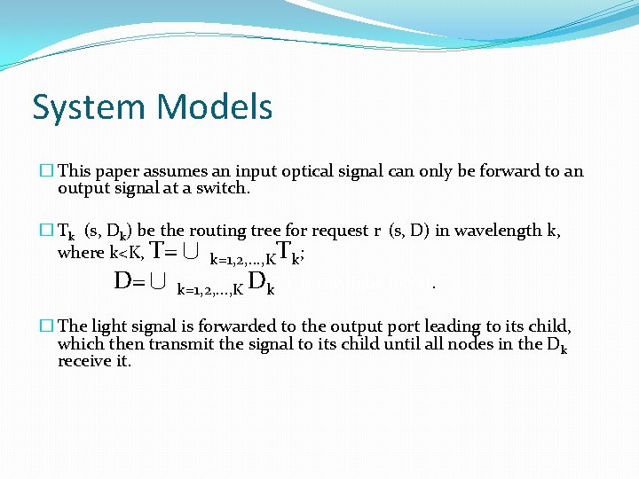
System Models � This paper assumes an input optical signal can only be forward to an output signal at a switch. � Tk (s, Dk) be the routing tree for request r (s, D) in wavelength k, where k<K, T=∪ k=1, 2, . . . , KTk; D=∪ k=1, 2, . . . , K Dk; T is the light-forest. � The light signal is forwarded to the output port leading to its child, which then transmit the signal to its child until all nodes in the D k receive it.
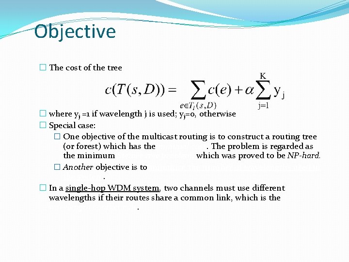
Objective � The cost of the tree � where yj =1 if wavelength j is used; yj=0, otherwise � Special case: � One objective of the multicast routing is to construct a routing tree (or forest) which has the minimal cost. The problem is regarded as the minimum Steiner tree problem, which was proved to be NP-hard. � Another objective is to minimize the number of wavelengths used in the system. � In a single-hop WDM system, two channels must use different wavelengths if their routes share a common link, which is the wavelength conflict rule.
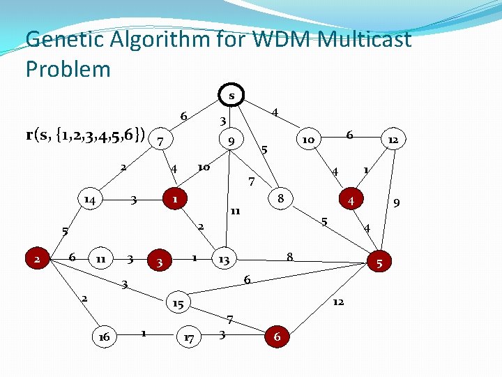
Genetic Algorithm for WDM Multicast Problem s 6 r(s, {1, 2, 3, 4, 5, 6}) 9 10 4 3 14 3 7 2 5 8 11 3 11 1 3 4 5 2 12 15 16 5 6 3 1 7 17 3 6 9 4 8 13 12 1 4 2 6 6 10 7 1 5 2 4
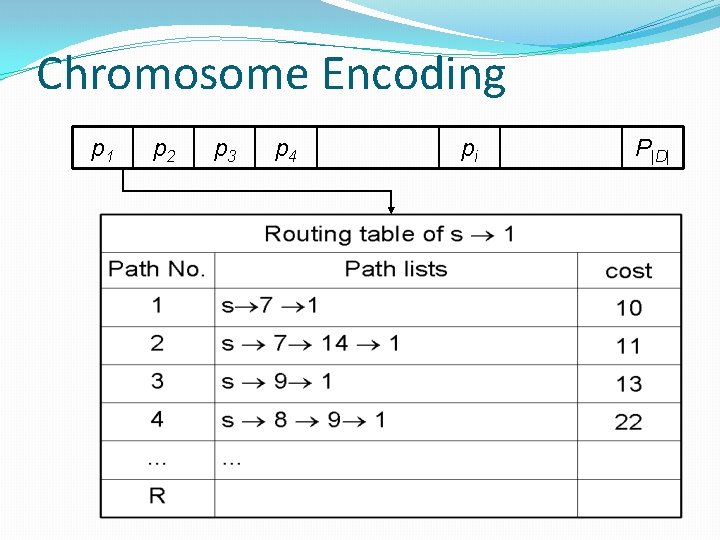
Chromosome Encoding p 1 p 2 p 3 p 4 pi P|D|
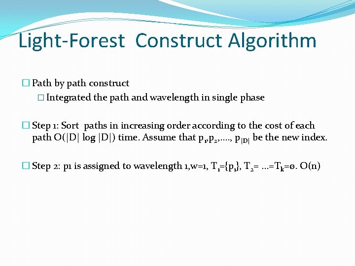
Light-Forest Construct Algorithm � Path by path construct � Integrated the path and wavelength in single phase � Step 1: Sort paths in increasing order according to the cost of each path O(|D| log |D|) time. Assume that p 1, p 2, . . , p|D| be the new index. � Step 2: p 1 is assigned to wavelength 1, w=1, T 1={p 1}, T 2=. . . =Tk=ø. O(n)
Light-Forest Construct Algorithm � Step 3: For i= 2 to |D] do � Begin � j=1 � while j≦w do � { � if pi is not conflict with Tj � then � {assigned pi to Tj � Tj=Tj ∪pi � flag=TRUE} � else j=j+1 � } � if flag is not TRUE � then � w=w+1 � Tw=Tw ∪ pi � End
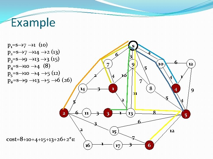
Example p 1=s 7 1 (10) p 2=s 7 14 2 (13) p 3=s 9 13 3 (15) p 4=s 10 4 (8) p 5=s 10 4 5 (12) p 6=s 9 13 5 6 (26) s 6 7 2 9 10 4 3 14 11 1 3 4 5 8 5 1 17 12 7 3 6 9 4 6 15 16 8 12 1 4 13 3 2 cost=8+10+4+15+13+26+2*α 3 5 11 2 6 6 10 7 1 5 2 4 3
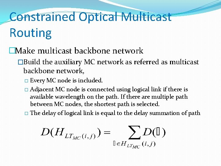
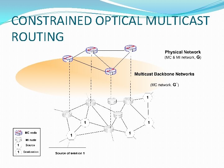
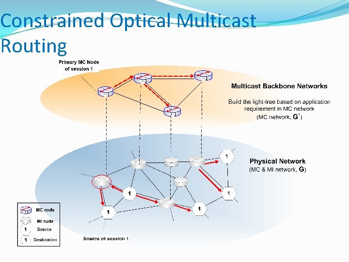
Constrained Optical Multicast Routing �Make multicast backbone network �Build the auxiliary MC network as referred as multicast backbone network, Every MC node is included. � Adjacent MC node is connected using logical link if there is available wavelength on the path. If there are multiple path between MC nodes, the shortest path is selected. � The delay of logical link is equal to the delay summation of path �
CONSTRAINED OPTICAL MULTICAST ROUTING
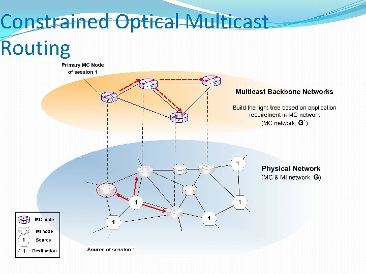
Constrained Optical Multicast Routing �Build the light-tree based on application requirement � Source searches the MC node which is nearest from source as referred to primary MC node. � The primary MC node is unique of each session � Build the light-tree which has primary MC node as root in multicast backbone network based on constraints.
Constrained Optical Multicast Routing
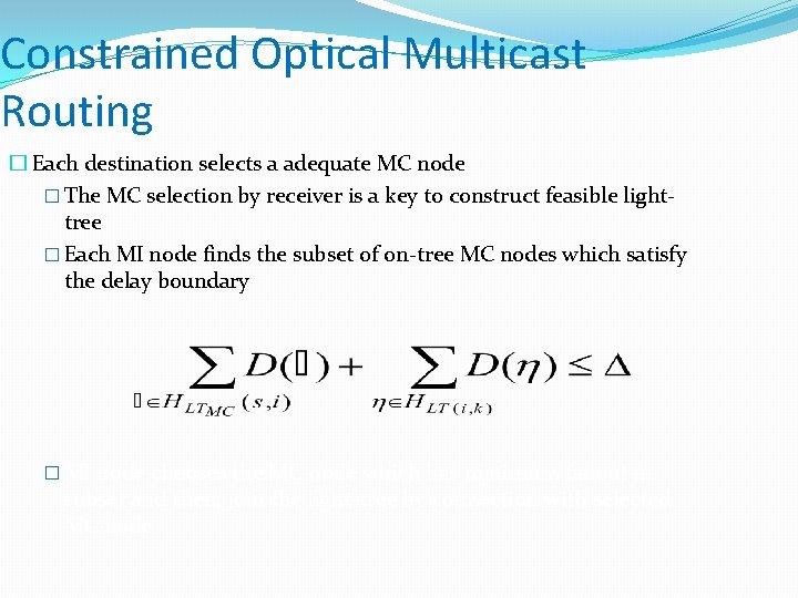
Constrained Optical Multicast Routing � Each destination selects a adequate MC node � The MC selection by receiver is a key to construct feasible lighttree � Each MI node finds the subset of on-tree MC nodes which satisfy the delay boundary � MI node chooses the MC node which has minimum fanout in subset and then, join the light-tree by connection with selected MC node
Constrained Optical Multicast Routing
Constrained Optical Multicast Routing Advantages � Source need not know about the location of destinations. Every destination need not find the minimum cost path from itself to source. It just must find the location of MC node which satisfies application requirement. � Simple construction of member-only light-tree The procedure of joining the light-tree is only performed at member. � The procedure of dynamic addition or deletion of members in a group is simple. Join: The node which wants to join in the multicast session can be connected to its nearest MC node. Leave: The node which wants to leave can be disconnected send the prune message to connected MC node.
Related Work The main mechanism of transport over optical network is lightpath, a point to point all optical channel connecting from source to destination. To incorporate optical multicasting capability, a light-tree, lightforest concept is introduced. The problem of constructing a light-tree that spans a given source and a set of destinations is similar to the Steiner tree problem which is known to be NP-complete Consider several new issues and complexities for Qo. S provisioning of optical multicasting � Sparse splitting (X. Zhang, J. Wei and C. Qiao, “Constrained Multicast Routing in WDM Networks with Sparse Light Splitting, ” in J. of Lightwave Technology, vol. 18, no. 12, December 2002. ) � Power constraint (Y. Xin and G. Rouskas, “Multicast routing under optical layer constraints, ” In Proc. of INFOCOM 2004) � Delay boundary (M. Chen, S. Tseng, B. Lin, “Dynamic multicast routing under delay constraints in WDM networks with heterogeneous light splitting capabilities, ” in Computer Communications 29 (2006) 1492 -1503)
Conclusion & Future Work � To support multicast in optical network � a balanced light-tree to guarantee signal quality � Delay and inter-destination delay variation along all sourcedestination paths in the tree should be bounded in sparse splitting optical network. � The proposed algorithm is heuristic approach to obtain the feasible light-tree � Wavelength assignment algorithm should be explored in future research. � Minimize wavelength cost
THANK YOU PRESENTED BY Ø Seminartopics. info