Light Sources List two type of semiconductors Optical


 #- Insulator are good conductor / falls #- Gold")
 #- List 3 semi conductor materials ? 02/01/2022")
 #- Explain or what is depletion region ?")


 #- Give three advantages for LED ? #-Easy fabrication is a")


 #-Give three types of liberation shape ? The answer")
")
 #- Sketch the behavior of laser comparison with LED ?")

 #-Give the equation for MSR ? The answer")

 #-Explain DFL ? The answer is written and grave •")


 #- What is the main advantage for lens coupling ?")

 • Tree coupler – Distributes incoming light to several")


 • Sensitivity – The minimum optical input power can be")


 2. Pre-amplifier – Used to amplify the weak")
 3. #what is the main job of power")


- Slides: 45
Light Sources #- List two type of semiconductors ? • Optical sources are used to convert electrical signals into optic beams thus enables information carrying facility though the fiber core. • Generally, the information is put into the beam by modulating the source input current. • Two basic types which rely on semiconductor principles of operation are – Light emitting diodes (LEDs) – Laser diodes (LDs) 02/01/2022 TTC Riyadh, ICT–BS-2. 3/2 1
Light Sources Considerations #- Which requirement should be matched in the fiber optic ? • The light source must be matched with the fiber in terms of – Size – Modal characteristics – Numerical aperture – Line width – Fiber-window wavelength range – Transmitted power 02/01/2022 TTC Riyadh, ICT–BS-2. 3/2 2
Conduction of Electrons Conduction band Current flow Movement of electrons Valance band #- Make a sketch over the conduction of electrons ? #- The direction of the current with the condition of electronic s the same of current flow / falls • When a small voltage is placed across the conductor, electrons in the outermost shell move from the valance band to conductor band. • This results positively charged “holes’ in the valance band. • Then, the holes are appeared to be moved to the negative source terminal and electrons are to the positive terminal. • Therefore, it said the a current flows through the circuit in the opposite direction of electrons flow. 02/01/2022 TTC Riyadh, ICT–BS-2. 3/2 3
Conduction of Electrons (Contd. ) #- Insulator are good conductor / falls #- Gold is a good conductor / true #- Copper is a semi conductor / falls • Good conductors have few electrons on the valance band. • On the otherhand, insulators (poor conductors) have a full valence band thus it requires more energy to make current flowing (actually they are not). • In addition, there are semiconductor materials, which requires more energy to allow current flowing than in a conductor. 02/01/2022 TTC Riyadh, ICT–BS-2. 3/2 4
Composition of the Semi-conductor (Contd. ) #- List 3 semi conductor materials ? 02/01/2022 TTC Riyadh, ICT–BS-2. 3/2 5
The pn Junction Diode (Contd. ) #- Explain or what is depletion region ? Depletion region is the region where the electrons and protons hits together and produced energy ( current ) • Even without applying any voltage, a barrier is formed at the boundary. This is called ad the depletion region. p-type n-type Potential barrier/ depletion region 02/01/2022 TTC Riyadh, ICT–BS-2. 3/2 6
Compare between reverse biased and forward pn-junction ? ﺗﺮﺳﻢ ﺍﻟﺮﺳﻤﺘﺎﻥ ﻭﺗﻜﺘﺐ ﻣﻘﺎﺭﻧﻪ
Reverse Biased - pn Junction • When an external voltage is applied with the positive voltage to the n-side and negative voltage to the p-side, the barrier becomes larger. • Therefore, a very small current is flown through the circuit. • This is happened due to the surplus electrons are moved for p-to-n. • This is called as reverse current and the circuit is called as in reverse biased. p-type n-type ﻳﻨﻘﺺ ﺍﻟﺘﻴﺎﺭ Increased depletion region 02/01/2022 TTC Riyadh, ICT–BS-2. 3/2 8
Forward Biased - pn Junction • However, once the external voltage is applied such that positive voltage for p-side and negative for n-side, then the depletion region becomes shrink. • Now, it is possible to move more electrons, thus a larger current is produced. • This is the forward biased current. p-type n-type ﻳﺰﻳﺪ ﺍﻟﺘﻴﺎﺭ Reduced depletion region 02/01/2022 TTC Riyadh, ICT–BS-2. 3/2 9
LED (Contd. ) #- Give three advantages for LED ? #-Easy fabrication is a reason of the LED / true • Eventhough LED has a less attraction with optical systems, it can be still used because of – Simple fabrication – Cost – Reliability (no catastrophic degradation, immune to modal noise) – Less temperature dependency – Simpler drive circuitry (lower drive currents) – Linearity (linear light output versus current) 02/01/2022 TTC Riyadh, ICT–BS-2. 3/2 10
LED Operation #- Hole is combination between electron + photon / falls Photon = electron + hole #- In the valence band are the photon / falls • Electron – Proton + Photon + - When a conduction band electron falls back to the valence band, this electron gets recombined with a hole, thus creates a photon (electron + hole) • As a result this photon creation, light gets emitted. • This is a spontaneous process according to the Planck’s law. Conduction band Band gap energy Valance band 02/01/2022 TTC Riyadh, ICT–BS-2. 3/2 11
#Function of LED ? For how LED works The movement of electrons in the depletion region and hits the
#- Give two types of band gap transition and explain it ? Direct transition+ ﺍﺭﺳﻢ ﺭﺳﻤﺘﻬﺎ in direct transition + ﺍﺭﺳﻢ ﺭﺳﻤﺘﻬﺎ
Types of Band gap Transitions #- Give two types of band gap transition and explain it ? • There is no changes in the momentum (direction) in direct band gap transition. • However, some energy must be used for momentum changes in indirect band gap transition. Therefore, direct transition acquires more efficiency than the indirect transition. ------ Conduction band ------ Energy Momentum ++++ Valance band (Direct transition) 02/01/2022 ++++ • Valance band (Indirect transition) TTC Riyadh, ICT–BS-2. 3/2 14
#- Explain the different between homojunction and hetrojunction LED
Composition of the Semi-conductor • Eventhough many semi-conductor materials can be induced to emit light, an appropriate composition can enhance the efficiency of the system by minimizing the waste of energy. • The primary target is to reduce the band gap energy. • Normally, two elements are compounded from Group III materials (Aluminum, Gallium, Indium) and Group V materials (Phosphorous, Arsenic) in the periodic table. 02/01/2022 TTC Riyadh, ICT–BS-2. 3/2 16
LED Physical Structure • Basically a fabricated LED structure can be – either a homojunction structure (when p- and n-side have same base material). – or a heterojunction structure (when p- and n-side have different base materials so that it is formed a waveguide at the junction) (Heterojunction structure) (Homojunction structure) 02/01/2022 TTC Riyadh, ICT–BS-2. 3/2 17
Surface Emitting Diode #-What is Surface Emitting Diode ? • When refractive indices of both p- and n-type materials are same, light is free to come out from all sides of the semi-conductor device because there is no confinement. • However, only the active region near (but not on) the surface will emit a significant amount of light while reabsorbing from the other parts. Therefore, this is called as surface emitting LED. 02/01/2022 TTC Riyadh, ICT–BS-2. 3/2 18
Surface Emitting Diode (Contd. ) #-Give three types of liberation shape ? The answer is grave • However, a large amount of power generated by the LED get wasted. • To increase the output power, only allowing the light be exit from the surface can be done while confining from others. • The output beam makes a Lambertian shape. number of photons coming from the device at an angle of 02/01/2022 TTC Riyadh, ICT–BS-2. 3/2 per second. 19
Laser Principles #-Give the name for the below sketch ( LED / laser ) ? grave #- Sketch the LED / laser in spectral width ? Same 2 • The spectral width (line width) of the laser is much narrower than the LED Laser #-What are the characteristics of the laser ? • All lasers must have the following characteristics. – Pumping threshold – Output spectrum – Radiation pattern 02/01/2022 TTC Riyadh, ICT–BS-2. 3/2 20
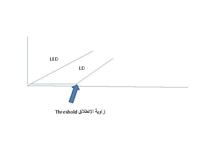
Laser Principles (Contd. ) #- Sketch the behavior of laser comparison with LED ? Grave Pumping threshold – The input power to a laser must be above than a threshold level to make it acts as an emitter whereas an LED radiates even at low levels of input current. – The device behaves like an LED, before it is reached to the threshold. Optical power / (m. W) • LED Laser Current / (m. A) LED region (Spontaneous) 02/01/2022 TTC Riyadh, ICT–BS-2. 3/2 Laser region (Stimulated) 21
Laser Operation #- What is laser ? • LASER – Light Amplification by Stimulated Emission of Radiation • The laser operation differs from other optical sources because of it is resulted from stimulated emissions. Conduction band External photon Stimulated photon Valance band 02/01/2022 TTC Riyadh, ICT–BS-2. 3/2 22
Laser Output Mode Structure (Contd. ) #-Give the equation for MSR ? The answer is equation • Normally, the device can be tuned to in favor of single longitudinal mode (main lobe). • Therefore, a measure called mode-suppression ratio (MSR) is introduced as • In decibels, 02/01/2022 TTC Riyadh, ICT–BS-2. 3/2 23
Physical Structure – Laser Diode #- Sketch a laser Diode ? The answer is the grave • Laser diodes has a similar structure to edge-emitting LED. • However, it has a thinner active region (gain-guided). • In addition, it consists of : - strip contacts to high density current injection - cladding thickness variations to fabricate a ridge waveguide Cleaved surface (mirror) Active layer Cladding layer Active layer Metallic layer 02/01/2022 TTC Riyadh, ICT–BS-2. 3/2 24
Distributed Feedback Laser (DFL) #-Explain DFL ? The answer is written and grave • A Braggy grating inside the heterostructure is used to select one reflective wavelength. • Slopes of the grating generate a distributed reflection which couples both forward and backward travelling waves and a single wavelength is supported. • Therefore, a powerful output can be obtained with even a smaller linewidth. Grating Mirror Active region Distributed Feedback Laser (DFL) 02/01/2022 TTC Riyadh, ICT–BS-2. 3/2 25
Advantages of LD over LED #- Give 2 or 3 advantages for LD over LED ? • A higher radiance due to amplifying effect of the stimulated emission. – Optical output power in m. W • Narrower linewidth minimizes the effect of material dispersion. – Order of 1 nm or less • Extension of modulation capabilities upto GHz range. • Applicability of heterodyne (coherent) detection in high capacity systems. • Good spatial coherent allows efficient coupling into the fibers even with low numerical apertures thus results a higher efficiency. 02/01/2022 TTC Riyadh, ICT–BS-2. 3/2 26
Source-to-Fiber Coupling #- What is the main objectives of Source-to-Fiber Coupling ? • The main objective of the coupling mechanism is to couple much light into the fiber. #- give 3 -4 losses in optical fiber ? General question • However, several losses may arise due to reflection loss, area mismatch, packing fraction loss and numerical aperture mismatch. • Two basic types – Lens coupling – Direct coupling 02/01/2022 TTC Riyadh, ICT–BS-2. 3/2 27
Source-to-Fiber Coupling (Contd. ) #- What is the main advantage for lens coupling ? • Lens coupling – Approximately 100% efficiency is achievable by using lens coupling – Sometimes suffers from lens mounting problems Cylindrical lens Source 02/01/2022 Cylindrical lens Spherical lens Fiber TTC Riyadh, ICT–BS-2. 3/2 28
Fiber Optic Couplers #- Give three types of signal coupling ? The answer is blue line • Fiber optic couplers transmit one or more fiber inputs to one or more fiber outputs. • Therefore, it is possible to transmit the same signal to two places or to provide bidirectionality and isolation. • Star coupler – Number of inputs are coupled to number of outputs 02/01/2022 TTC Riyadh, ICT–BS-2. 3/2 29
Fiber Optic Couplers (Contd. ) • Tree coupler – Distributes incoming light to several outputs evenly. • Tee (tap) coupler – Three ports, one input and two outputs and third port can be used for monitoring purposes by taking out a portion of the output signal. 02/01/2022 TTC Riyadh, ICT–BS-2. 3/2 30
Optical Detectors #- what is main objective of optical detector ? Is to convert the optical to electrical signal • Photo detection process is used to convert the optical signal back to the electrical signal at the receiver. • The common light detectors are semiconductor junction devices. #- What is the basic principle of optical detection ? • The basic principle used for detection is optical absorption. #- Give 3 -4 types of optical detectors ? • Type of optical detectors (AP) – pn-junction photodiode – Positive-intrinsic-negative (PIN) photodiode – Avalanche (AP) photodiode – Metal-semiconductor-metal (MSM) photodiode 02/01/2022 TTC Riyadh, ICT–BS-2. 3/2 31
#-What is the main job / function of recever • Receiver is responsible for converting the optical signal back to the original information set by the transmitter. #-What are the basic subsections in the recever The basic subsections in the receiver are the photodiode, low noise pre-amplifier, main amplifier section and the data recovery stage
#/ give to types of receiver • The receivers can be categorized as – analog receivers and *Photodiode *Pre-amplifier *amplifier • Eventhough digital signal transmission is preferred in optical communication, – digital receivers. #what is the ffunction of there are many potential applications for analog transmission. • It ranges from individual 4 k. Hz voice channels to multi-GHz microwave links. #- Sketch the process /component of analog / digital receiver Photodiode Optical Signal Power Supply (Front End) Preamplifier Amplifier Filter Output Automatic Gain Control (Main Amplifier) (Data Recovery)
Digital Receiver #where do you find the different between analog and digital recevier ? • The notable difference in the digital receiver is the data recovery subsection compared to the analog receiver because the analog receiver data recovery can be done directly by using the demodulator. • However, the digital one requires further signal processing. • It consists of a decision circuit and a clock recovery circuit. Preamplifier Amplifier Photodiode Filter Decision Circuit Optical Signal Power Supply (Front End) 02/01/2022 Automatic Gain Control (Main Amplifier) TTC Riyadh, ICT–BS-2. 3/2 Output Clock Recovery (Data Recovery) 34
Signal Recovery in a Digital receiver ﺗﺎﺑﻊ ﺍﻟﺴﺆﺎﻝ ﺍﻻﻭﻝ • This is responsible of checking the validity of the received information. • The decision circuit is used to separate bits (to either ones or zeros) of the received data. The data is compared with a threshold level. – If the received voltage is more than the threshold will results bit “ 1”. – Otherwise bit “ 0”. • To accomplish this bit interpretation, the receiver should be able to understand the bit boundaries. • The clock recovery circuit measures the bit interval and regenerates a new clock pulse to the decision circuit. • However, to minimize the bit error rate, the receiver should be capable of detecting and correcting the errors of the received data stream. 02/01/2022 TTC Riyadh, ICT–BS-2. 3/2 36
Receiver Performance #Give three characteristics for receiver the performance ? • Receiver performance is determined by transforming the received optical signal to meaningful data. • To evaluate the receiver performance, dynamic range, sensitivity, SNR and bit error rate can be used. • Dynamic range – The amount of signal level can be detected with a linear response. – Sometimes at high powers, the receivers may become nonlinear thus anomalies can be occurred. – Typical range is 30 to 40 d. B. 02/01/2022 TTC Riyadh, ICT–BS-2. 3/2 37
Receiver Performance (Contd. ) • Sensitivity – The minimum optical input power can be detected by the receiver. – This determines the quality of the service, i. e. , for a given SNR, the minimum input optical power needed. • Signal-to-noise ratio (SNR) – This determines detectability of the signal with the addition of noise. • Bit error rate (BER) – The average probability of incorrect bit identification. – If there is one error bit for every 109 bits, then BER is 10 -9. 02/01/2022 TTC Riyadh, ICT–BS-2. 3/2 38
Transceiver #What is a transceiver ? • By combining the transmitter and the receiver also can increase the performance of the transmission. Transceiver = Transmitter + Receiver (Connector) Laser Diode Control Electronics Data Out (Transmitter) Electroabsorption Modulator Laser Diode Drive Power Supply Amplifier With AGC Data In Fiber Connector Data Recovery Circuit Photodiode Filter Pre-amp Fiber Connector (Receiver) 02/01/2022 TTC Riyadh, ICT–BS-2. 3/2 39
Amplifiers #give the reason for using the amplifiers ? • Amplifiers are needed to increase the amplitude of the detected signal. • However, the bandwidth should remain unchanged and also the amplification of the noise part has to be minimized for a proper communication. • Amplifiers are consist of transistors, resistors and other components. • In fiber optic transmission, number of amplification stages are used especially in long distance communication. 02/01/2022 TTC Riyadh, ICT–BS-2. 3/2 40
Type of Optical Amplifiers #Give three types of amplifiers ? 1. In-line optical amplifier – In single-mode fiber transmission, the effect of signal dispersion is very less. – Therefore, the transmission can be done by regenerating the signal without using repeaters in between. – Thus, the main purpose of in-line amplifier is compensating for transmission loss and increasing the distance between repeaters. Fiber cable Optical Tx Optical Rx G In-line amplifier 02/01/2022 TTC Riyadh, ICT–BS-2. 3/2 41
Type of Optical Amplifiers (Contd. ) 2. Pre-amplifier – Used to amplify the weak optical signal before the photodetection. – Thus SNR reduced because of thermal noise effect can be suppressed. – Provides a larger gain factor and also increases the bandwidth. Fiber cable Optical Tx G Optical Rx Pre- amplifier 02/01/2022 TTC Riyadh, ICT–BS-2. 3/2 42
Type of Optical Amplifiers (Contd. ) 3. #what is the main job of power amplifier? Power amplifier – Used to boost the transmitted power thus to increase the transmission distance by 10100 km. – Placed immediately after the optical transmitter. – This techniques is used with pre-amplifier in undersea transmission where repeaters can not be installed. Long fiber link Optical Tx Optical Rx G Power amplifier 02/01/2022 TTC Riyadh, ICT–BS-2. 3/2 43
Repeaters and Regenerators #what are the components of repeater ? *Optical receiver *Amplifier *Optical transmitter • A repeater consists of an optical receiver, an amplifier and an optical transmitter. • An optical signal is first converted into electrical signal, then amplified and next converted back to the optical mode (optical-electrical-optical conversion). • Regenerator is required to remove the noise and generate a clean signal for further transmission. • Discriminator is used to separate the noise from the signal and retiming is required to make sure that the pulse timing is in order. 02/01/2022 TTC Riyadh, ICT–BS-2. 3/2 44
Types of Regenerators ﻣﻬﻤﻪ ﻣﻦ ﻋﻨﺪ ﺳﺎﻣﻲ #Give the types of regenerators ? #What is the function of regenerator ? *Remove the noise *Clean the signal • Three regenerator types. – 1 R device : Amplifying only – 2 R device : Amplifying and reshaping – 3 R device : Amplifying, reshaping and retiming #Sketch the all types of regenerators ? Input Output R Re-amplify 2 R Re-amplify, Re-shape 3 R Re-amplify, Re-shape, Re-time 02/01/2022 TTC Riyadh, ICT–BS-2. 3/2 45