
Light Sources and Future Prospects R Bartolini Diamond
Light Sources and Future Prospects R. Bartolini Diamond Light Source Ltd and John Adams Institute, University of Oxford Io. P NPPD Glasgow, 06 April 2011
Outline • Introduction synchrotron radiation properties and users’ requirements • 3 rd generation light sources performance, trends and limitations • 4 th generation light sources AP and FEL challenges and enabling R&D • beyond 4 th generation Laser plasma accelerators driven light sources • Conclusions Io. P NPPD Glasgow, 06 April 2011
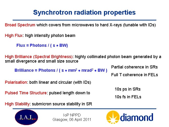
Synchrotron radiation properties Broad Spectrum which covers from microwaves to hard X-rays (tunable with IDs) High Flux: high intensity photon beam Flux = Photons / ( s BW) High Brilliance (Spectral Brightness): highly collimated photon beam generated by a small divergence and small size source Partial coherence in SRs 2 2 Brilliance = Photons / ( s mm mrad BW ) Full T coherence in FELs Polarisation: both linear and circular (with IDs) Pulsed Time Structure: pulsed length down to High Stability: submicron source stability in SR Io. P NPPD Glasgow, 06 April 2011 10 s ps in SRs 10 s fs in FELs
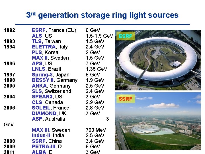
3 rd generation storage ring light sources 1992 1993 1994 1996 1997 1998 2000 2004 2006: Ge. V 2008 2009 2011 ESRF, France (EU) ALS, US TLS, Taiwan ELETTRA, Italy PLS, Korea MAX II, Sweden APS, US LNLS, Brazil Spring-8, Japan BESSY II, Germany ANKA, Germany SLS, Switzerland SPEAR 3, US CLS, Canada SOLEIL, France DIAMOND, UK ASP, Australia 6 Ge. V 1. 5 -1. 9 Ge. V 1. 5 Ge. V 2. 4 Ge. V 2 Ge. V 1. 5 Ge. V 7 Ge. V 1. 35 Ge. V 8 Ge. V 1. 9 Ge. V 2. 5 Ge. V 2. 4 Ge. V 3 Ge. V 2. 9 Ge. V 2. 8 Ge. V 3 MAX III, Sweden Indus-II, India SSRF, China PETRA-III, D ALBA, E 700 Me. V 2. 5 Ge. V 3. 4 Ge. V 6 Ge. V 3 Ge. V ESRF SSRF
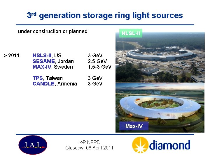
3 rd generation storage ring light sources under construction or planned > 2011 NLSL-II NSLS-II, US SESAME, Jordan MAX-IV, Sweden 3 Ge. V 2. 5 Ge. V 1. 5 -3 Ge. V TPS, Taiwan CANDLE, Armenia 3 Ge. V Max-IV Io. P NPPD Glasgow, 06 April 2011
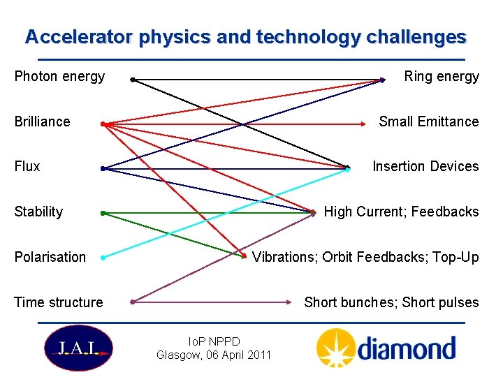
Accelerator physics and technology challenges Photon energy Ring energy Brilliance Small Emittance Flux Insertion Devices Stability Polarisation High Current; Feedbacks Vibrations; Orbit Feedbacks; Top-Up Time structure Short bunches; Short pulses Io. P NPPD Glasgow, 06 April 2011
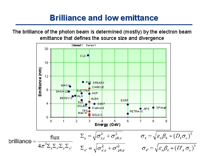
Brilliance and low emittance The brilliance of the photon beam is determined (mostly) by the electron beam emittance that defines the source size and divergence Series 1 20 CLS Emittance (nm) 16 12 PLS SPEAR 3 MAX-II 8 SAGA-LS BESSY-II CANDLE ELETTRA ALS ALBA SLS SOLEIL 4 PETRA-III 2 SPring 8 APS NSLS-II 0 1 ESRF SSRF Diamond TPS Max-IV 0 ASP 3 4 5 Energy (Ge. V) 6 7 8 9
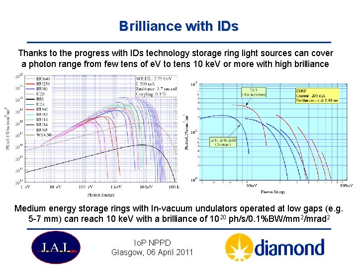
Brilliance with IDs Thanks to the progress with IDs technology storage ring light sources can cover a photon range from few tens of e. V to tens 10 ke. V or more with high brilliance Medium energy storage rings with In-vacuum undulators operated at low gaps (e. g. 5 -7 mm) can reach 10 ke. V with a brilliance of 1020 ph/s/0. 1%BW/mm 2/mrad 2 Io. P NPPD Glasgow, 06 April 2011
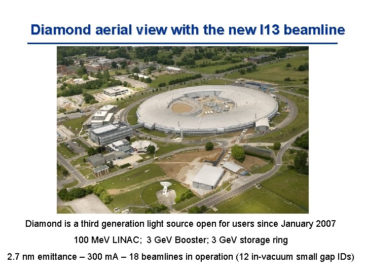
Diamond aerial view with the new I 13 beamline Diamond is a third generation light source open for users since January 2007 100 Me. V LINAC; 3 Ge. V Booster; 3 Ge. V storage ring 2. 7 nm emittance – 300 m. A – 18 beamlines in operation (12 in-vacuum small gap IDs)
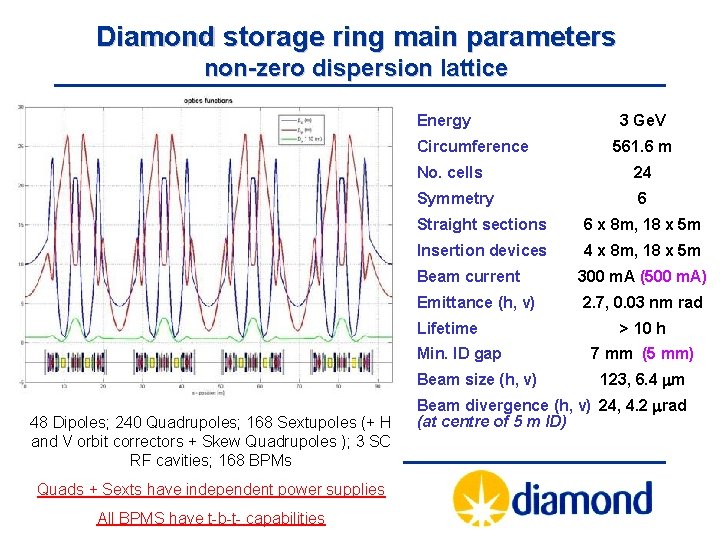
Diamond storage ring main parameters non-zero dispersion lattice Energy Circumference 24 Symmetry 6 Straight sections 6 x 8 m, 18 x 5 m Insertion devices 4 x 8 m, 18 x 5 m Beam current 300 m. A (500 m. A) Emittance (h, v) 2. 7, 0. 03 nm rad Min. ID gap Beam size (h, v) Io. P NPPD Quads + Sexts have independent power supplies Glasgow, 06 April 2011 All BPMS have t-b-t- capabilities 561. 6 m No. cells Lifetime 48 Dipoles; 240 Quadrupoles; 168 Sextupoles (+ H and V orbit correctors + Skew Quadrupoles ); 3 SC RF cavities; 168 BPMs 3 Ge. V > 10 h 7 mm (5 mm) 123, 6. 4 m Beam divergence (h, v) 24, 4. 2 rad (at centre of 5 m ID)
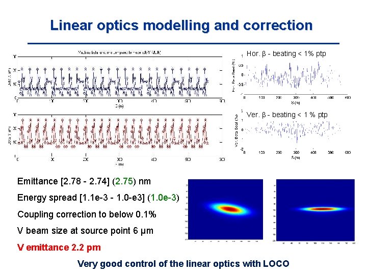
Linear optics modelling and correction Hor. - beating < 1% ptp Ver. - beating < 1 % ptp Emittance [2. 78 - 2. 74] (2. 75) nm Energy spread [1. 1 e-3 - 1. 0 -e 3] (1. 0 e-3) Coupling correction to below 0. 1% V beam size at source point 6 μm V emittance 2. 2 pm Very good control of the linear optics with LOCO
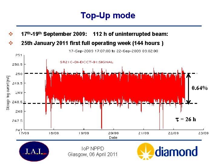
Top-Up mode v 17 th-19 th September 2009: 112 h of uninterrupted beam: v 25 th January 2011 first full operating week (144 hours ) 0. 64% t = 26 h Io. P NPPD Glasgow, 06 April 2011
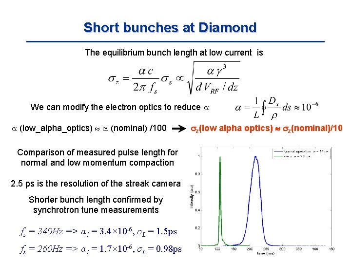
Short bunches at Diamond The equilibrium bunch length at low current is We can modify the electron optics to reduce (low_alpha_optics) (nominal) /100 Comparison of measured pulse length for normal and low momentum compaction 2. 5 ps is the resolution of the streak camera Shorter bunch length confirmed by synchrotron tune measurements fs = 340 Hz => α 1 = 3. 4× 10 -6, σL = 1. 5 ps fs = 260 Hz => α 1 = 1. 7× 10 -6, σL = 0. 98 ps z(low alpha optics) z(nominal)/10
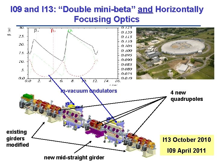
I 09 and I 13: “Double mini-beta” and Horizontally Focusing Optics in-vacuum undulators existing girders modified 4 new quadrupoles I 13 October 2010 I 09 April 2011 new mid-straight girder
Trends in 3 rd generation light sources Striving to meet advanced user’s requirements more beamlines (canted undulator from single straight sections) customised optics higher brightness (low emittance – low coupling) higher flux (higher current) short pulses New machine designs or upgrades are targeting 100 pm or less in the horizontal plane … but peak brightness and pulses length cannot compete with FELs Io. P NPPD Glasgow, 06 April 2011
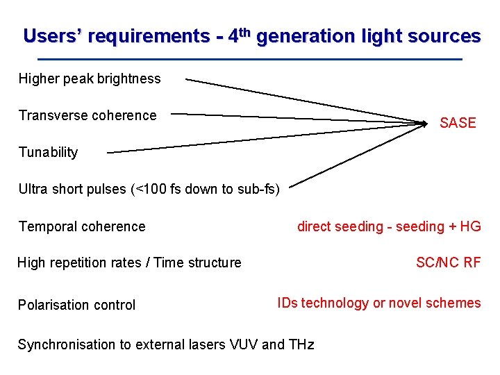
Users’ requirements - 4 th generation light sources Higher peak brightness Transverse coherence SASE Tunability Ultra short pulses (<100 fs down to sub-fs) Temporal coherence direct seeding - seeding + HG High repetition rates / Time structure Polarisation control SC/NC RF IDs technology or novel schemes Synchronisation to external lasers VUV and THz
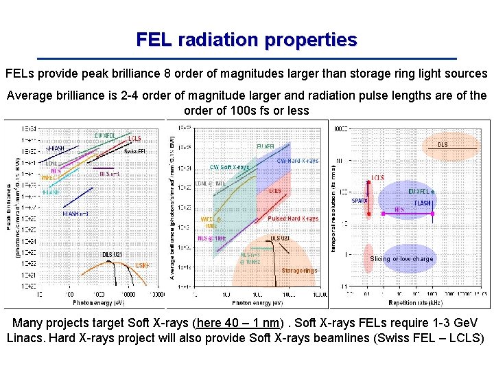
FEL radiation properties FELs provide peak brilliance 8 order of magnitudes larger than storage ring light sources Average brilliance is 2 -4 order of magnitude larger and radiation pulse lengths are of the order of 100 s fs or less Slicing or low charge Many projects target Soft X-rays (here 40 – 1 nm). Soft X-rays FELs require 1 -3 Ge. V Linacs. Hard X-rays project will also provide Soft X-rays beamlines (Swiss FEL – LCLS)
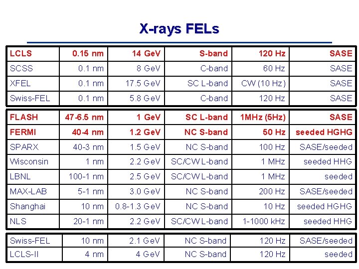
X-rays FELs LCLS 0. 15 nm 14 Ge. V S-band 120 Hz SASE SCSS 0. 1 nm 8 Ge. V C-band 60 Hz SASE XFEL 0. 1 nm 17. 5 Ge. V SC L-band CW (10 Hz) SASE Swiss-FEL 0. 1 nm 5. 8 Ge. V C-band 120 Hz SASE FLASH 47 -6. 5 nm 1 Ge. V SC L-band 1 MHz (5 Hz) SASE FERMI 40 -4 nm 1. 2 Ge. V NC S-band 50 Hz seeded HGHG SPARX 40 -3 nm 1. 5 Ge. V NC S-band 100 Hz SASE/seeded 1 nm 2. 2 Ge. V SC/CW L-band 1 MHz seeded HHG 100 -1 nm 2. 5 Ge. V SC/CW L-band 1 MHz seeded MAX-LAB 5 -1 nm 3. 0 Ge. V NC S-band 200 Hz SASE/seeded Shanghai 10 nm 0. 8 -1. 3 Ge. V NC S-band 10 Hz seeded HGHG 20 -1 nm 2. 2 Ge. V SC/CW L-band 1 -1000 k. Hz seeded HHG 10 nm 2. 1 Ge. V NC S-band 120 Hz SASE/seeded 4 nm 4 Ge. V NC S-band 120 Hz seeded Wisconsin LBNL NLS Swiss-FEL LCLS-II
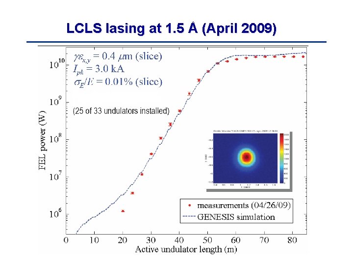
LCLS lasing at 1. 5 Å (April 2009)
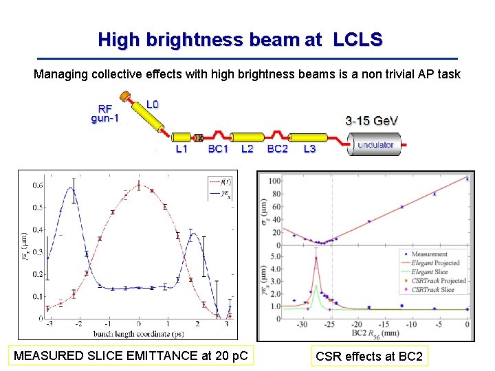
High brightness beam at LCLS Managing collective effects with high brightness beams is a non trivial AP task MEASURED SLICE EMITTANCE at 20 p. C CSR effects at BC 2
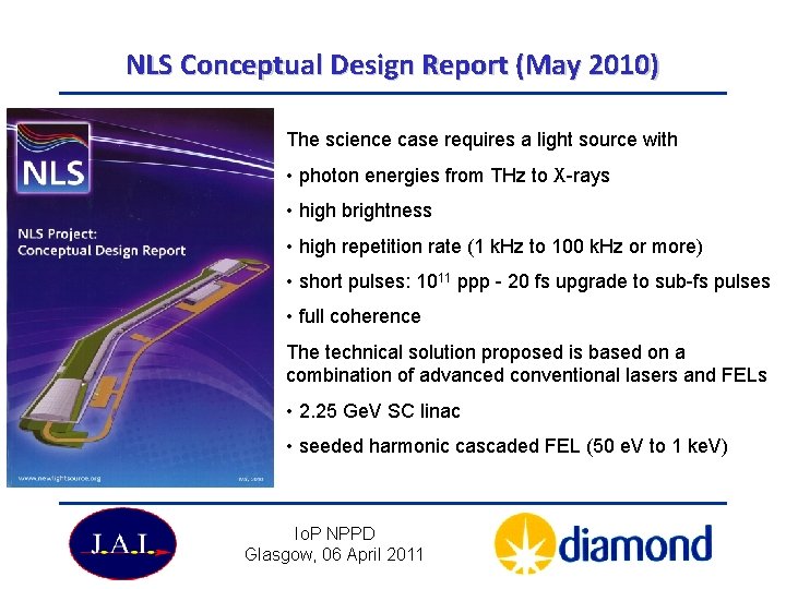
NLS Conceptual Design Report (May 2010) The science case requires a light source with • photon energies from THz to X-rays • high brightness • high repetition rate (1 k. Hz to 100 k. Hz or more) • short pulses: 1011 ppp - 20 fs upgrade to sub-fs pulses • full coherence The technical solution proposed is based on a combination of advanced conventional lasers and FELs • 2. 25 Ge. V SC linac • seeded harmonic cascaded FEL (50 e. V to 1 ke. V) Io. P NPPD Glasgow, 06 April 2011
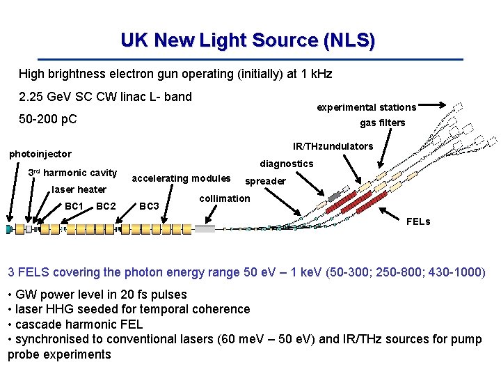
UK New Light Source (NLS) High brightness electron gun operating (initially) at 1 k. Hz 2. 25 Ge. V SC CW linac L- band experimental stations 50 -200 p. C gas filters IR/THzundulators photoinjector 3 rd harmonic cavity diagnostics accelerating modules laser heater BC 1 BC 2 BC 3 spreader collimation FELs 3 FELS covering the photon energy range 50 e. V – 1 ke. V (50 -300; 250 -800; 430 -1000) • GW power level in 20 fs pulses • laser HHG seeded for temporal coherence • cascade harmonic FEL • synchronised to conventional lasers (60 me. V – 50 e. V) and IR/THz sources for pump probe experiments
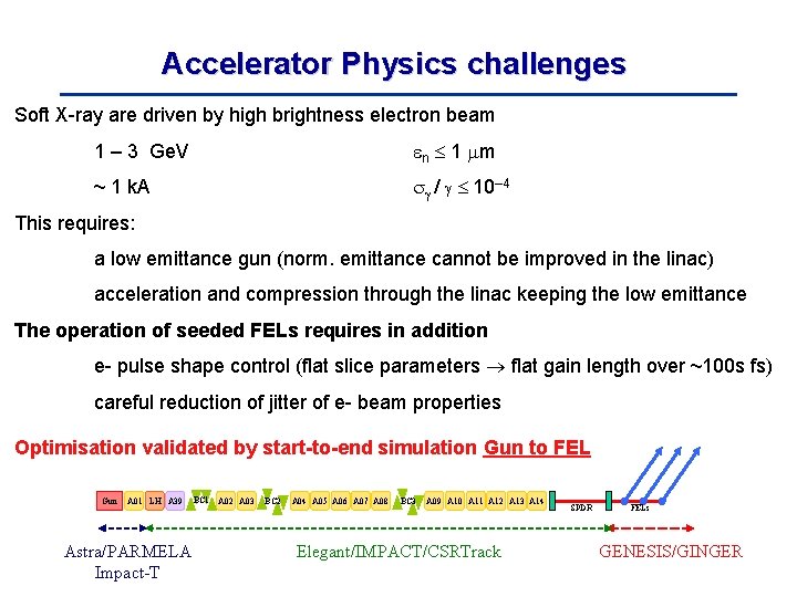
Accelerator Physics challenges Soft X-ray are driven by high brightness electron beam 1 – 3 Ge. V n 1 m ~ 1 k. A / 10– 4 This requires: a low emittance gun (norm. emittance cannot be improved in the linac) acceleration and compression through the linac keeping the low emittance The operation of seeded FELs requires in addition e- pulse shape control (flat slice parameters flat gain length over ~100 s fs) careful reduction of jitter of e- beam properties Optimisation validated by start-to-end simulation Gun to FEL Gun A 01 LH A 39 Astra/PARMELA Impact-T BC 1 A 02 A 03 BC 2 A 04 A 05 A 06 A 07 A 08 BC 3 A 09 A 10 A 11 A 12 A 13 A 14 Elegant/IMPACT/CSRTrack SPDR FELs GENESIS/GINGER
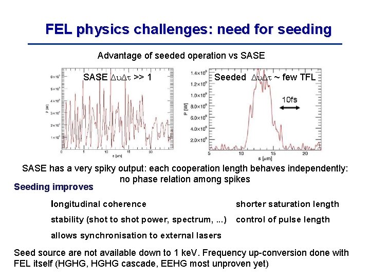
FEL physics challenges: need for seeding Advantage of seeded operation vs SASE >> 1 Seeded ~ few TFL SASE has a very spiky output: each cooperation length behaves independently: no phase relation among spikes Seeding improves longitudinal coherence shorter saturation length stability (shot to shot power, spectrum, . . . ) control of pulse length allows synchronisation to external lasers Seed source are not available down to 1 ke. V. Frequency up-conversion done with FEL itself (HGHG, HGHG cascade, EEHG most unproven yet)
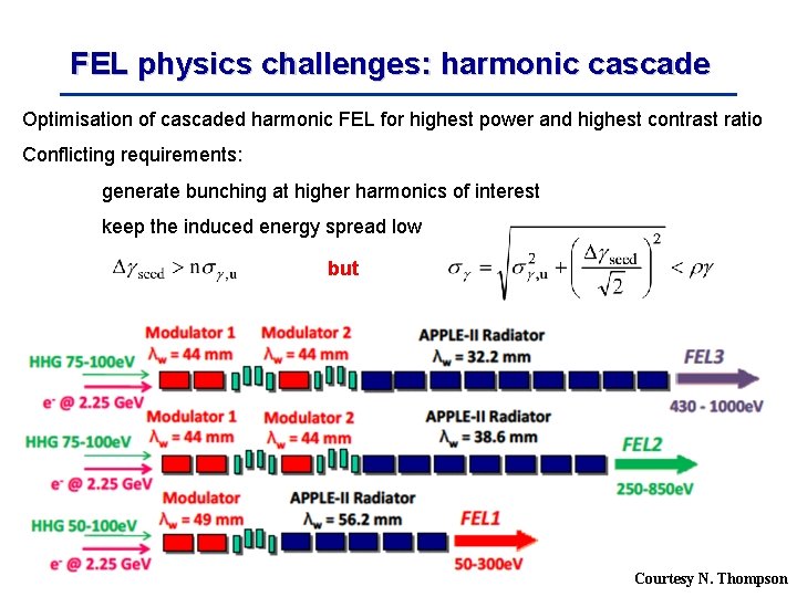
FEL physics challenges: harmonic cascade Optimisation of cascaded harmonic FEL for highest power and highest contrast ratio Conflicting requirements: generate bunching at higher harmonics of interest keep the induced energy spread low but Courtesy N. Thompson
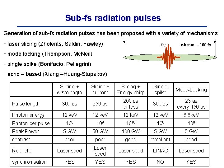
Sub-fs radiation pulses Generation of sub-fs radiation pulses has been proposed with a variety of mechanisms • laser slicing (Zholents, Saldin, Fawley) e-beam ~ 100 fs • mode locking (Thompson, Mc. Neil) • single spike (Bonifacio, Pellegrini) • echo – based (Xiang –Huang-Stupakov) Slicing + wavelength Slicing + current Slicing + Energy chirp Single spike Mode-Locking Pulse length 300 as 250 as 200 as or less 300 as 23 as every 150 as Photon energy 12 ke. V 8. 6 ke. V 108 109 1010 108 Peak Power 5 GW 50 GW 100 GW 5 GW contrast poor good excellent good Rep rate Laser seed LINAC Laser seed YES YES NO YES Photon per pulse synchronisation
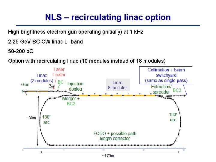
NLS – recirculating linac option High brightness electron gun operating (initially) at 1 k. Hz 2. 25 Ge. V SC CW linac L- band 50 -200 p. C Option with recirculating linac (10 modules instead of 18 modules) Linac 8 modules
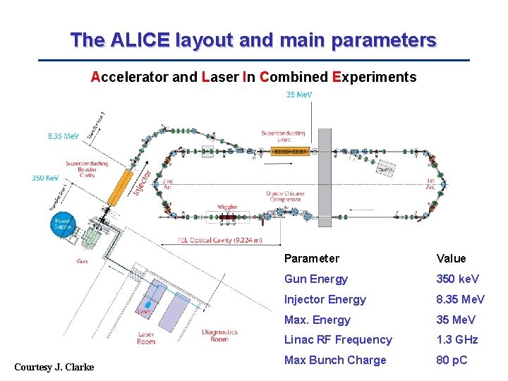
The ALICE layout and main parameters Accelerator and Laser In Combined Experiments Courtesy J. Clarke Parameter Value Gun Energy 350 ke. V Injector Energy 8. 35 Me. V Max. Energy 35 Me. V Linac RF Frequency 1. 3 GHz Max Bunch Charge 80 p. C
The ALICE electron test accelerators An R&D facility dedicated to accelerator science and technology Offers a unique combination of accelerator, laser and free-electron laser sources Enabling studies of electron and photon beam combination techniques Provides a range of photon sources for development of scientific programmes and techniques Highlights of the scientific programme include R&D on SC DC photoinjectors and on SC RF for CW L-band Linacs Diagnostics (e. g. ultrashort pulses) timing and synchronisation Energy recovery - Emma injector Compton backscattering - THz radiation and IR-FEL Io. P NPPD Glasgow, 06 April 2011
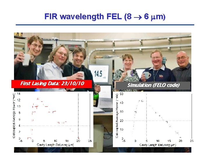
FIR wavelength FEL (8 6 m) First Lasing Data: 23/10/10 Simulation (FELO code)
Possible future directions for 4 th generation light sources • Ultracold injectors: low emittance, low charge, to shorten the saturation length • Insertion Devices: development of new undulators beyond Apple-II, compact, shorter periods, higher fields, wakefield control, compact (e. g. Superconducting U) • RF: Optimise performance and reduce cost of SC RF (gradient choices 13 -15 MV/m for LBNL, NLS, BESSY) or use simple low risk design with high gradient (possibly high repetition rate based on C-band X-band) • FEL physics: Critical assessment of various seeding schemes, non-seeding and slicing options, HHG, HGHG cascade and sub fs pulses • AP Physics: alternative compression schemes to avoid the limits posed by microbunching (velocity bunching) • Diagnostics: New diagnostics for ultra short bunches, arrival time, low charge but also dealing with COTR • Timing and synhcronisation: sub 10 -fs resolution over 100 s m; long term stability • Stability and feedbacks: positions (sub m over large frequency range), energy, charge, …
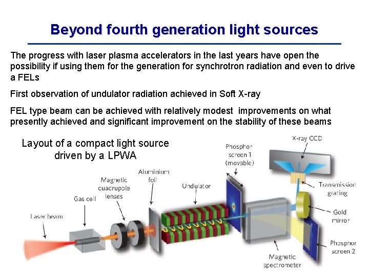
Beyond fourth generation light sources The progress with laser plasma accelerators in the last years have open the possibility if using them for the generation for synchrotron radiation and even to drive a FELs First observation of undulator radiation achieved in Soft X-ray FEL type beam can be achieved with relatively modest improvements on what presently achieved and significant improvement on the stability of these beams Layout of a compact light source driven by a LPWA

LBNL-Oxford experiment (2006) Laser plasma wakefield accelerators demonstrated the possibility of generating Ge. V beam with promising electron beam qualities W. P. Leemans et al. Nature Physics 2 696 (2006) E = 1. 0 +/-0. 06 Ge. V ΔE = 2. 5% r. m. s Δθ = 1. 6 mrad r. m. s. Q = 30 p. C charge Capillary: 310 μm Laser: 40 TW Density: 4. 3 × 1018 cm-3 Density 4. 3 1018 cm– 3 Laser Power > 38 TW (73 fs) to 18 TW (40 fs) Io. P NPPD Glasgow, 06 April 2011
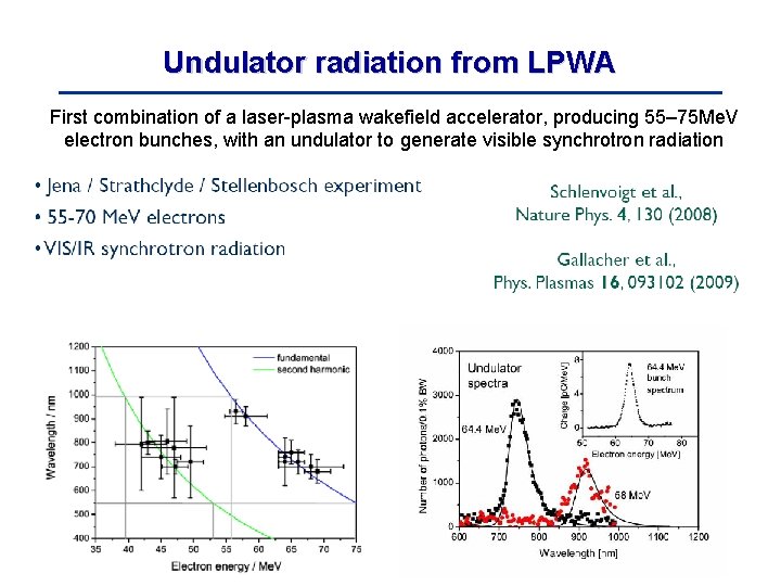
Undulator radiation from LPWA First combination of a laser-plasma wakefield accelerator, producing 55– 75 Me. V electron bunches, with an undulator to generate visible synchrotron radiation
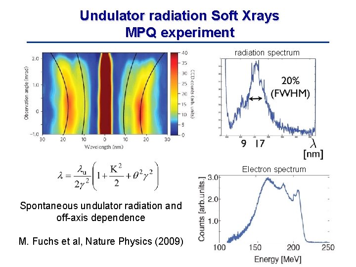
Undulator radiation Soft Xrays MPQ experiment radiation spectrum Electron spectrum Spontaneous undulator radiation and off-axis dependence M. Fuchs et al, Nature Physics (2009)
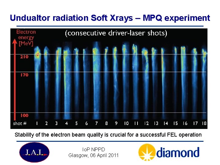
Undualtor radiation Soft Xrays – MPQ experiment Stability of the electron beam quality is crucial for a successful FEL operation Io. P NPPD Glasgow, 06 April 2011
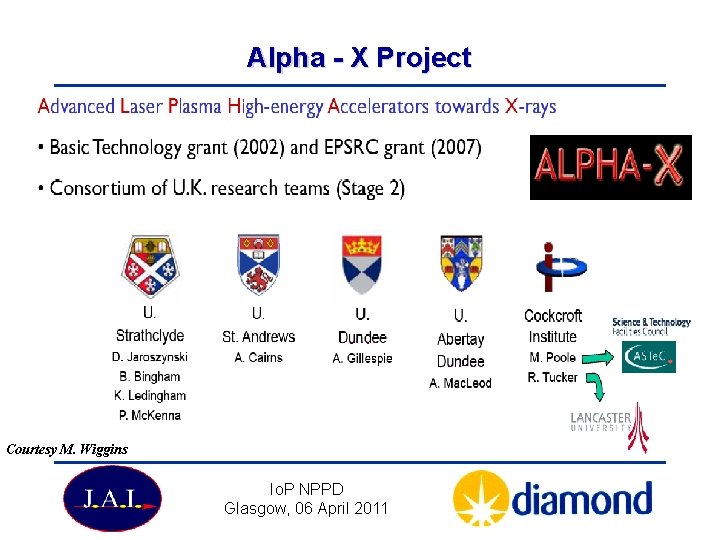
Alpha - X Project Courtesy M. Wiggins Io. P NPPD Glasgow, 06 April 2011
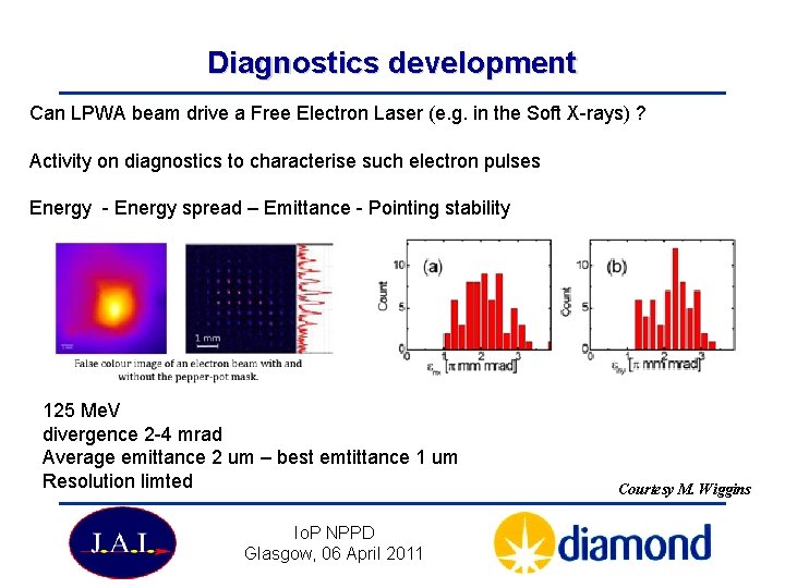
Diagnostics development Can LPWA beam drive a Free Electron Laser (e. g. in the Soft X-rays) ? Activity on diagnostics to characterise such electron pulses Energy - Energy spread – Emittance - Pointing stability 125 Me. V divergence 2 -4 mrad Average emittance 2 um – best emtittance 1 um Resolution limted Io. P NPPD Glasgow, 06 April 2011 Courtesy M. Wiggins
Alpha X - Summary Beam quality appear to be close to the one required for driving FEL in the UV - XUV: 170 Me. V beam Measured emittance below 1 m Charge 1 – 5 p. C in 2 fs corresponding to 1 -2 k. A Measured energy spread better 1% should be sufficient at least to measure FEL gain in the XUV range Progress is advancing nicely towards a working compact soft X-ray driven by a LPWA electron beam based on gas jet or capillary accelerator talk by D: Jarosinsky tomorrow Io. P NPPD Glasgow, 06 April 2011
Conclusions Users’ requirements pose difficult challenges for storage ring and FEL design and operation The methods and solutions developed show that these challenges can be met. Experimental tests of seeding in the coming future will confirm the extent of seeding capabilities to cover the whole Soft X-ray spectrum down to 1 nm However, more compact and economic solutions to meet the present challenges are needed: Injectors – IDs – LINACs RF technology …. LPWA Thank you for your attention. Io. P NPPD Glasgow, 06 April 2011
- Slides: 40