Light Scattering Rayleigh Scattering Mie Scattering Theory Characteristics


 • Using the same procedure to observe the Rayleigh")


- Slides: 16
Light Scattering Rayleigh Scattering & Mie Scattering
Theory • Characteristics of Polystyrene and Sulphur Nanoparticles. -- Non absorbing -- Refractive index is a weak function of wavelength. • How does light interact with objects? -- Reflection (light deviated from its original path) -- Refraction -- Diffraction -- Absorption (light absorbed and converted to heat)
Theory Cont… • A collimated light source is the most basic tool for nanoparticle work. Often called a Tyndall beam. • The Tyndall effect is the scattered path of light observed in the suspension. Examples: Milk, smoke, Lake Thunderbird. • Scattering Plane -- The scattering plane is defined by the two rays involved, the sourceparticle ray and the particle-observer ray. -- The scattering plane is determined by observation, it is not fixed in space. For example, if the observer moves, the scattering plane will move with the observer.
Theory Cont…. • Theory of Rayleigh -- Particles are treated as electric dipole. • Results: -- I 1/ λ 4 (only true if the refractive index is a weak function of λ, i. e. not a metal. ) -- I r 6 -- scattered light at 90° is linearly polarized perpendicular to the scattering plane. Verticle Source Polarization Horizontal Source Polarization
Theory Cont… • Mie Scattering -- Absorption and Scattering by a Sphere. -- Multipole expansion (EM modes of a sphere) -- electric dipole. -- magnetic dipole, electric quadrupole. -- magnetic quadrupole, electric octupole. • If d < λ/20 then only the first term (dipole) is needed. In this limiting case, Mie’s theory reduces to Rayleigh’s theory. • Efficiency factors: Qsca, Qabs, Qext – Plot Qext vs λ for the extinction spectra – Qsca and Qabs vs λ show their contribution to Qext. • Intensity for perpendicular and parallel polarized light – Plot I vs θ for the angular intensity dependence for each polarization.
Objective • • Learn about Scattering plane The Polarization of Rayleigh Scattering Mie Scattering Angular Dependence
Procedure Rayleigh scattering • Using a light source and polarization lens we observed the way light rays are polarized through rayleigh scattering in different solutions: Silica SOL, Sulfur SOL and Fine Sulfur particles, by shining the light source through the solutions • Shine light source though solutions in a dark room • Place polarized lens in path of light source to observe polarization effects of scattered light in the scattering plane and outside of scattering plane, I. E. view from top (90 degrees) and other angles of observation
Higher Order Tyndall Spectra (HOTS) • Using the same procedure to observe the Rayleigh scattering effects, observe the different colors associated with the scattered light and observe angle dependency • Note the number of orders in each sample, one order is one color change from red to green
Scattering Angle • • • Using the Helium Neon laser apparatus (wavelength = 543. 5 mm) the laser beam was shone through our samples of polystyrene latex The samples were placed at an angle on the observation stage to avoid multiple reflection of the laser beam in the same area of the solution Note the minimum intensity zones in the scattered light by observing in the horizontal plane and recording the angle these minima occur. This was done by observing from about 35 degrees to 145 degrees from the laser beam in the scattering plane. See picture Laser Sample Observation stage with angle measurement site
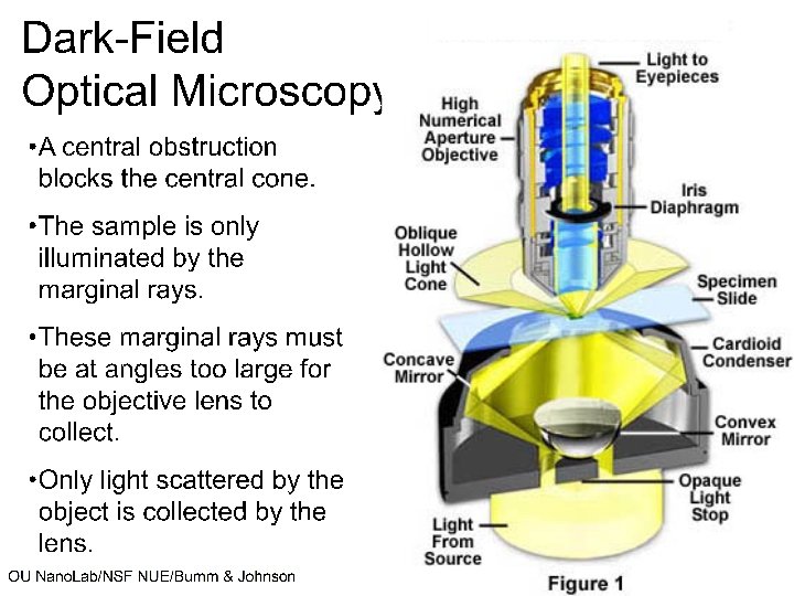
Optical Microscopy • Using an optical microscope in dark field observation mode, observe the nanoparticles in each of the three samples • Note their movement and size (each sample resembles a night sky filled with stars, the particles can be seen but not studied in detail)
Results: Rayleigh Scattering • Silica SOL – With the vertical polarization lens in place we noticed there is no angular dependence in the scattering plane – By using a second polarization lens at a 90 degree angle we verified that the light is polarized perpendicular to the scattering plane • Sulphur SOL – Using the same techniques we noted the HOTS followed slightly different result patterns, there was significantly more forward scattering which caused the scattered light to blend together and appear simply white toward larger scattering angles in the scattering plane • Polystyrene latex – By observing each of the three samples and noting their order using the HOTS phenomenon we ranked the sample by particle size from smallest to largest as follows: Sample C, Sample B, Sample A (This initial ranking seemed to be correct according to our scattering angle experiment data)
Observation Sample A Gaurav 50 74 98 Trevor 49 73 100 124 Ye 85 98 105 B 54 96 50 98 C 141 141
Results: Scattering Angle • Sample C – No minimum were found in this sample although the intensity significantly decreased as the viewing angle decreased, this result is consistant with the Mie plot data – Estimated particle size <240 nm • Sample B – Minima recorded at scattering angles of 54 and 96 degrees – Estimated particle size 600 nm • Sample A – Minima recorded at 50, 74 and 98 degrees – Estimated particle size 1060 nm
Mie plot results Sample C: Particle size < 240 nm Sample A: Particle size = 1060 nm ~ 50 ~74 ~98 Intensity decreases as angle increases Sample B: Particle size = 600 nm ~54 ~ 96
Experiment discussion • Experimentally determined particle size – Sample A: Particle size 1060 nm – Sample B: Particle size 600 nm – Sample C: Particle size < 240 nm • Error and procedure improvement suggestions – Lab results were recorded by human observation of three different lab technicians, humans always make mistakes • These results could be improved my taking more measurements and averaging results • Mono-dispersed vs. Poly-dispersed HOTS – A more highly dispersed sample would appear more “milky” under observation, that is to say the light spectrum would be blended together and appear more like white light instead a showing distinct wavelengths