LIGHT REFRACTION 1 Refraction of Light 2 Laws

 of")


 a μb = a μb sin")
 a μb = bμ c =")
 bμ a = a μb =")
 Total Internal Reflection (TIR) is the phenomenon of")
 Critical angle is the")


 is the point on the principal axis at which the incident")


 When object is placed at infinity: Parallel")
 When object (AB) is placed beyond C 1 (2 F 1): A 2")
 When object (AB) is placed at C 1 (2 F 1): A B")
 When object (AB) is placed between C 1 (2 F 1) & F")
 When object (AB) is placed at F 1: A • 2 F 1")
 When object (AB) is placed between F 1 & O: (Simple Microscope) A’")


 1. The object")


- Slides: 30
LIGHT - REFRACTION 1. Refraction of Light 2. Laws of Refraction 3. Refractive Index 4. Refraction through a Parallel Slab 5. Refractive Indices of Different Media 6. Principle of Reversibility of Light 7. Refraction through a Compound Slab 8. Apparent Depth of a Liquid 9. Total Internal Reflection 10. Refraction by Spherical Lenses 11. Image Formation by a Convex Lens 12. Image Formation by a Concave Lens 13. New Cartesian Sign Conventions 14. Lens Formula, Linear Magnification & Power of a Lens Created by C. Mani, Principal, K V No. 1, AFS, Jalahalli West, Bangalore
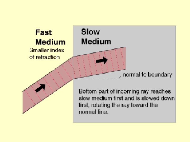
Refraction of Light: Refraction is the phenomenon of change in the path (direction) of light as it travels from one transparent medium to another (when the ray of light is incident obliquely). It can also be defined as the phenomenon of change in speed of light from one transparent medium to another. Laws of Refraction: I Law: The incident ray, the normal to the refracting surface at the point of incidence and the refracted ray all lie in the same plane. II Law: For a given pair of media and for light of a given wavelength, the ratio of the sine of the angle of incidence to the sine of the angle of refraction is a constant. (Snell’s Law) i Rarer N Denser r N r μ i Rarer
Bending of Light N N B X i Rarer E c, μ 1 i A F r G D C Denser r v, μ 2 AB – Incident wavefront CD – Refracted wavefront XY – Refracting surface Y
Refractive Index: Refractive index of the 2 nd medium with respect to the 1 st medium is defined as the ratio of the sine of angle of incidence in the 1 st medium to the sine of angle of refraction in the 2 nd medium. μ 21 = 1μ 2 = sin i sin r (The constant 1μ 2 is called refractive index of the medium, i is the angle of incidence and r is the angle of refraction. ) Refractive index of the 2 nd medium with respect to the 1 st medium is also defined as the ratio of the speed of light in the 1 st medium to the speed of light in the 2 nd medium. μ 21 = 1μ 2 = Speed of light in 1 st medium Speed of light in 2 nd medium If the 1 st medium is vacuum or air, then the refractive index is called ‘absolute refractive index’. If ‘c’ is the speed of light in air and ‘v’ is the speed of light in the medium, then the absolute refractive index is given by μm = Speed of light in air Speed of light in medium = c v
Refraction through a Parallel Glass Slab: a μb = sin i 1 bμ a = sin r 1 sin i 2 i 1 N sin r 2 N But aμb x bμa = 1 sin i 1 sin r 1 x Rarer medium (a) sin i 2 sin r 2 t =1 r 1 δ i 2 Denser medium (b) M y It implies that i 1 = r 2 and i 2 = r 1 since i 1 ≠ r 1 and i 2 ≠ r 2. Rarer medium (a) μ r 2 TIPS: 1. μ of optically rarer medium is lower and that of a denser medium is higher. 2. μ of denser medium w. r. t. rarer medium is more than 1 and that of rarer medium w. r. t. denser medium is less than 1. (μair = μvacuum = 1) 3. In refraction, the velocity and wavelength of light change. 4. In refraction, the frequency and phase of light do not change. 5. a μm = ca / cm and aμm = λa / λm
Refractive Index of different media Material Medium Refractive Index Air 1. 0003 Canada balsam 1. 53 Ice 1. 31 Rock salt 1. 54 Water 1. 33 Alcohol 1. 36 Carbon disulphide 1. 63 Kerosene 1. 44 Dense flint glass 1. 65 Fused quartz 1. 46 Ruby 1. 71 Benzene 1. 50 Sapphire 1. 77 Crown glass 1. 52 Diamamond 2. 42
Principle of Reversibility of Light: (Not in Syllabus) a μb = a μb sin i bμ a = sin r x bμ a = 1 or a μb sin r sin i Rarer (a) i = 1 / bμ a Denser (b) r If a ray of light, after suffering any number of reflections and/or refractions has its path reversed at any stage, it travels back to the source along the same path in the opposite direction. N μ A natural consequence of the principle of reversibility is that the image and object positions can be interchanged. These positions are called conjugate positions.
Refraction through a Compound Slab: (Not in Syllabus) a μb = bμ c = c μa = a μb or or sin i 1 sin r 1 N i 1 Rarer (a) sin r 1 sin r 2 μa r 1 sin r 2 N Denser (b) r 1 μb sin i 1 x bμ c x c μ a = 1 a μb bμ c Denser (c) N r 2 x bμ c = aμc / aμb r 2 μc Rarer (a) i 1 μc > μb
Apparent Depth of a Liquid: (Not in Syllabus) bμ a = a μb = sin i or sin r hr ha = a μb = sin r N sin i Real depth Rarer (a) Apparent depth r Apparent Depth of a Number of Immiscible Liquids: n ha = ∑ h i / μi ha i=1 hr Apparent Shift: O’ Apparent shift = hr - ha = hr – (hr / μ) TIPS: = hr [ 1 - 1/μ] r μa i μb i Denser (b) O 1. If the observer is in rarer medium and the object is in denser medium then ha < hr. (To a bird, the fish appears to be nearer than actual depth. ) 2. If the observer is in denser medium and the object is in rarer medium then ha > hr. (To a fish, the bird appears to be farther than actual height. )
Total Internal Reflection: (Not in Syllabus) Total Internal Reflection (TIR) is the phenomenon of complete reflection of light back into the same medium for angles of incidence greater than the critical angle of that medium. N N Rarer (air) r = 90° ic O μa i > ic i Denser (glass) μg Conditions for TIR: 1. The incident ray must be in optically denser medium. 2. The angle of incidence in the denser medium must be greater than the critical angle for the pair of media in contact.
Relation between Critical Angle and Refractive Index: (Not in Syllabus) Critical angle is the angle of incidence in the denser medium for which the angle of refraction in the rarer medium is 90°. gμ a = or a μg sin i sin r = = sin ic sin 90° 1 gμa a μg = = sin ic 1 sin ic or 1 sin ic = a μg Red colour has maximum value of critical angle and Violet colour has minimum value of critical angle since, 1 sin ic = a μg = 1 a + (b/ λ 2) Also sin ic = λg λa Applications of T I R: 1. Mirage formation 2. Looming 3. Totally reflecting Prisms 4. Optical Fibres 5. Sparkling of Diamonds
Refraction by Spherical Lenses whose refracting surfaces are spherical are called ‘spherical lenses’. A spherical lens whose refracting surfaces are bulging outwards at the centre is called a ‘double convex lens’. It is thicker in the middle compared to the edges. A spherical lens whose refracting surfaces are curved inwards at the centre is called a ‘double concave lens’. It is thinner in the middle compared to the edges. Different types of Spherical Lenses Double Convex Double Concave Planoconvex Planoconcave Meniscus lenses Convexo. Concavoconcave Convex
First Principal Focus: First Principal Focus is the point on the principal axis of the lens at which if an object is placed, the image would be formed at infinity. F 1 f 1 Second Principal Focus: Second Principal Focus is the point on the principal axis of the lens at which the image is formed when the object is kept at infinity. F 2 f 2
Convex Lens Concave Lens M X’ C F M O F C X X’ f R N C O F F C X f R N Optic Centre (O) is the central point of a lens. Centre of curvature (C) is the centre of the imaginary sphere from which spherical lens is cut out. There are two centres of curvature on either side of the lens. Radius of curvature (R) is the distance between the optic centre and the centre of curvature. Principal axis (XPX’) is the line passing through the optic centre and the centre of curvature and extending to ∞. It is the normal to the lens at the pole.
Principal Focus (F) is the point on the principal axis at which the incident rays of light parallel to principal axis either really pass through or appear to pass through after getting refracted from the lens. There are two foci for the lens. Focal length (f) is the distance between the optic centre and the principal focus. Radius of curvature is approximately twice the focal length. R ≈ 2 f Aperture (MN) is the diameter of the refracting surface. Note that it is not the diameter of the sphere from which the lens is cut out.
Rays to be considered for drawing Ray Diagram The intersection of at least two refracted rays give the position of image of the point object. Any two of the following rays can be considered for locating the image. 1. A ray parallel to the principal axis, after refraction from a convex lens, passes through the principal focus on the other side of the lens. In case of a concave lens, the ray appears to diverge from the principal focus on the same side of the lens. X’ C F O F C X
2. A ray passing through the principal focus of a convex lens or a ray which is directed towards the principal focus of a concave lens, after refraction, will emerge parallel to the principal axis. X’ C F O F C X 3. A ray passing through the optic centre of a convex or concave lens, after refraction, will emerge without any deviation. X’ C F O F C X
Image formation by a convex lens 1) When object is placed at infinity: Parallel rays from ∞ 2 F 1 • F 2 • • O 2 F 2 • B i) Position of image: At F 2 ii) Nature of image : Real & inverted iii) Size of image : Very small (Highly Diminished)
2) When object (AB) is placed beyond C 1 (2 F 1): A 2 F 1 B • F 1 • • O F 2 • B’ 2 F 2 • A’ i) Position of image: Between C 2 (2 F 2) & F 2 ii) Nature of image : Real & inverted iii) Size of image : Smaller than object (Diminished)
3) When object (AB) is placed at C 1 (2 F 1): A B • 2 F 1 • • O F 2 • B’ 2 F 2 • A’ i) Position of image: At C 2 (2 F 2) ii) Nature of image : Real & inverted iii) Size of image : Same size as that of the object
4) When object (AB) is placed between C 1 (2 F 1) & F 1: A 2 F 1 • F 1 B • • O F 2 • 2 F 2 • B’ A’ i) Position of image: Beyond C 2 (2 F 2) ii) Nature of image : Real & inverted iii) Size of image : Larger than object (Enlarged)
5) When object (AB) is placed at F 1: A • 2 F 1 B • F 1 F 2 • • O 2 F 2 • Parallel rays meet at ∞ i) Position of image: At ∞ ii) Nature of image : Real & inverted iii) Size of image : Very large (Highly enlarged)
6) When object (AB) is placed between F 1 & O: (Simple Microscope) A’ A • 2 F 1 B’ • F 1 B • O F 2 • 2 F 2 • i) Position of image: On the same side as that of the object ii) Nature of image : Virtual & erect iii) Size of image : Larger than the object
Image formation by a convex lens for different positions of the object Position of the image Size of the image Nature of the image At infinity At F Highly diminished Real and inverted Beyond C Between F and C Diminished Real and inverted At C Same size Real and inverted Between F and C Beyond C Enlarged Real and inverted At F At infinity Highly enlarged Real and inverted Between O and F Same side of the lens Enlarged Virtual and erect
Image formation by a concave lens A A’ B • 2 F 1 • F 1 B’ • O F 2 • 2 F 2 • i) Position of image: On the same side as that of the object ii) Nature of image : Virtual & erect iii) Size of image : Smaller than the object
Sign Conventions for Refraction by Spherical Lenses (New Cartesian Sign Convention) 1. The object is always placed to the left of the lens. i. e. the incident rays from the object always move from left to right. 2. All distances parallel to the principal axis are measured from the optic centre (O) of the lens. 3. All the distances measured to the right of the optic centre (along +ve xaxis) are taken +ve while those measured to the left of the optic centre (along - ve x-axis) are taken –ve. 4. Distances measured perpendicular to and above the principal axis (along +ve y-axis) are taken +ve while those measured below the principal axis (along –ve y-axis) are taken –ve. Note: While solving numerical problems, new Cartesian sign convention must be used for substituting the known values of u, v, f, h and R.
Y Direction of incident light - ve + ve X’ + ve • O - ve X Y’ Y Direction of incident light - ve + ve X’ - ve + ve • O Y’ X
Lens Formula A M 2 F 1 • • B F 2 • • O 2 F 2 • u R B’ v f A’ 1 v - 1 u u – object distance = 1 f v – image distance f – focal length of the mirror
Linear Magnification: Linear magnification produced by a lens is defined as the ratio of the size of the image to the size of the object. Magnification produced by a lens is also defined as the ratio of the image distance to object distance. m = v h’ = h u Magnification in terms of v and f: m = Power of a Lens: Power of a lens is its ability to bend a ray of light falling on it and is reciprocal of its focal length. When f is in metre, power is measured in Dioptre (D). f-v f P = 1 f Magnification in terms of u and f: m = f f-u More of Refraction in Higher Class…