LIGHT EMMITING DIODELED INTRODUCTION The Light Emitting Diode
")


- Slides: 26
LIGHT EMMITING DIODE(LED)
INTRODUCTION §The “Light Emitting Diode” or LED as it is more commonly called, is basically just a specialized type of diode as they have very similar electrical characteristics to a PN junction diode. §This means that an LED will pass current in its forward direction but block the flow of current in the reverse direction. § Light emitting diodes are made from a very thin layer of fairly heavily doped semiconductor material and depending on the semiconductor material used and the amount of doping. § When forward biased an LED will emit a colored light at a particular spectral wavelength.
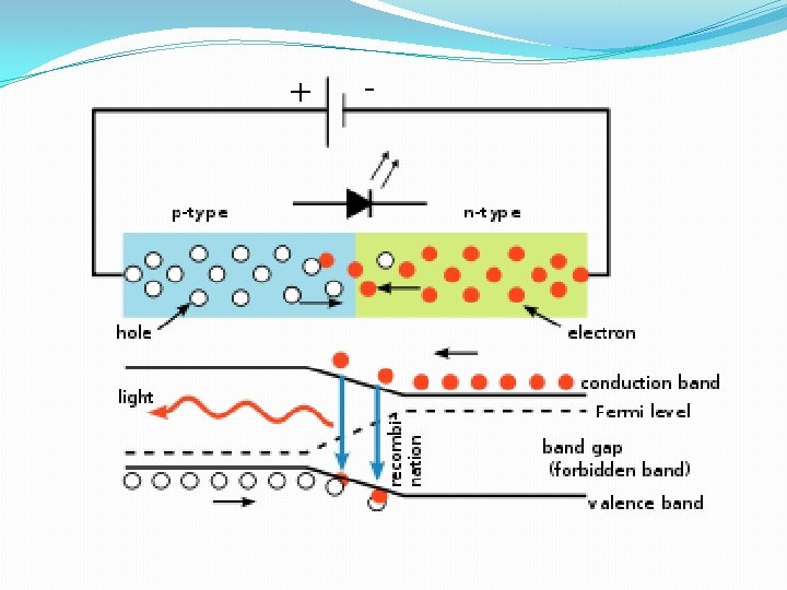
INTRODUCTION §When the diode is forward biased, electrons from the semiconductors conduction band recombine with holes from the valence band releasing sufficient energy to produce photons which emit a monochromatic (single color) of light. §Because of this thin layer a reasonable number of these photons can leave the junction and radiate away producing a colored light output.
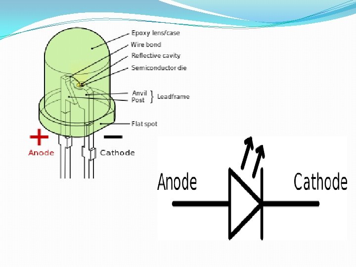
LED CONSTRUCTION §The construction of a Light Emitting Diode is very different from that of a normal signal diode. §The PN junction of an LED is surrounded by a transparent, hard plastic epoxy resin hemispherical shaped shell or body which protects the LED from both vibration and shock. § An LED junction does not actually emit that much light so the epoxy resin body is constructed in such a way that the photons of light emitted by the junction are reflected away from the surrounding substrate base to which the diode is attached and are focused upwards through the domed top of the LED, which itself acts like a lens concentrating the amount of light. § This is why the emitted light appears to be brightest at the top of the LED.
LED CONSTRUCTION §Not all LEDs are made with a hemispherical shaped dome for their epoxy shell. §Some indication LEDs have a rectangular or cylindrical shaped construction that has a flat surface on top or their body is shaped into a bar or arrow. Generally, all LED’s are manufactured with two legs protruding from the bottom of the body. §Nearly all modern light emitting diodes have their cathode, ( – ) terminal identified by either a notch or flat spot on the body or by the cathode lead being shorter than the other as the anode ( + ) lead is longer than the cathode (k).
LED Construction §Unlike normal incandescent lamps and bulbs which generate large amounts of heat when illuminated, the light emitting diode produces a “cold” generation of light which leads to high efficiencies than the normal “light bulb” because most of the generated energy radiates away within the visible spectrum. §Because LEDs are solid-state devices, they can be extremely small and durable and provide much longer lamp life than normal light sources.
LIGHT EMITTING DIODE COLORS §Unlike normal signal diodes which are made for detection or power rectification, and which are made from either Germanium or Silicon semiconductor materials. §Light Emitting Diodes are made from exotic semiconductor compounds such as Gallium Arsenide (Ga. As), Gallium Phosphide (Ga. P), Gallium Arsenide Phosphide (Ga. As. P), Silicon Carbide (Si. C) or Gallium Indium Nitride (Ga. In. N) all mixed together at different ratios to produce a distinct wavelength of color.
LIGHT EMITTING DIODE COLORS §Different LED compounds emit light in specific regions of the visible light spectrum and therefore produce different intensity levels. §The exact choice of the semiconductor material used will determine the overall wavelength of the photon light emissions and therefore the resulting color of the light emitted.
Light Emitting Diode Colors Semiconductor Material Wavelength Color Operating voltage Ga. As 850 -940 nm Infra-Red 1. 2 v Ga. As. P 630 -660 nm Red 1. 8 v Ga. As. P 605 -620 nm Amber 2. 0 v Ga. As. P: N 585 -595 nm Yellow 2. 2 v Al. Ga. P 550 -570 nm Green 3. 5 v Si. C 430 -505 nm Blue 3. 6 v Ga. In. N 450 nm White 4. 0 v
WORKING PRINCIPLE §A P-N junction can convert absorbed light energy into a proportional electric current. The same process is reversed here (i. e. the P-N junction emits light when electrical energy is applied to it). §This phenomenon is generally called electroluminescence, which can be defined as the emission of light from a semi-conductor under the influence of an electric field. §The charge carriers recombine in a forward-biased P-N junction as the electrons cross from the N-region and recombine with the holes existing in the P-region.
WORKING PRINCIPLE §Free electrons are in the conduction band of energy levels, while holes are in the valence energy band. §Thus the energy level of the holes will be lesser than the energy levels of the electrons. §Some portion of the energy must be dissipated in order to recombine the electrons and the holes. §This energy is emitted in the form of heat and light.
WORKING PRINCIPLE §The electrons dissipate energy in the form of heat for silicon and germanium diodes but in gallium arsenide phosphide (Ga. As. P) and gallium phosphide (Ga. P) semiconductors, the electrons dissipate energy by emitting photons. §If the semiconductor is translucent, the junction becomes the source of light as it is emitted, thus becoming a light-emitting diode. §When the junction is reverse biased no light will be produced by the LED and, on the contrary, the device may also be damaged.
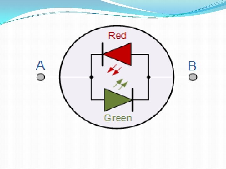
Bicolor Light Emitting Diodes §A bicolour light emitting diode has two LEDs chips connected together in “inverse parallel” (one forwards, one backwards) combined in one single package. §Bicolour LEDs can produce any one of three colors for example, a red color is emitted when the device is connected with current flowing in one direction and a green color is emitted when it is biased in the other direction. §This type of bi-directional arrangement is useful for giving polarity indication, for example, the correct connection of batteries or power supplies etc. § Also, a bi-directional current produces both colors mixed together as the two LEDs would take it in turn to illuminate if the device was connected (via a suitable resistor) to a low voltage, low frequency AC supply.
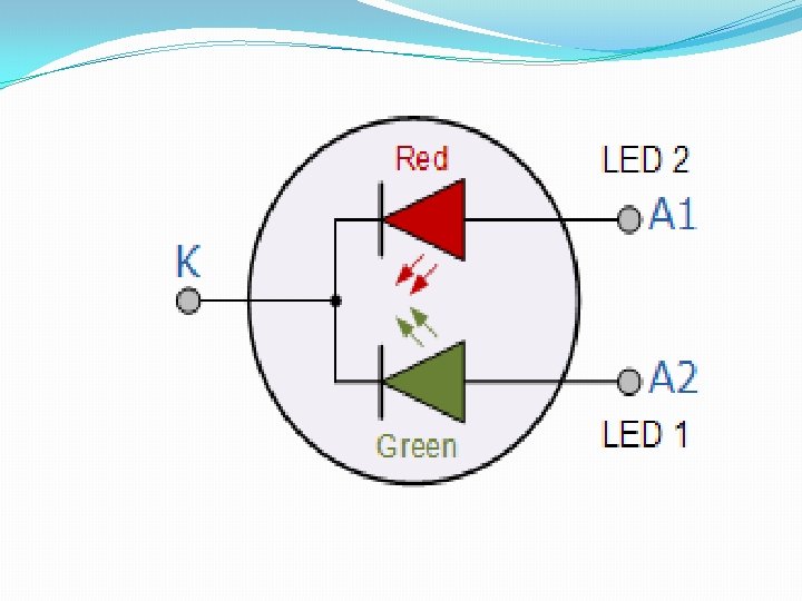
Tricolored Light Emitting Diode §The most popular type of tricolour light emitting diode comprises of a single Red and a Green LED combined in one package with their cathode terminals connected together producing a three terminal device. §They are called tricolour LEDs because they can give out a single red or a green color by turning “ON” only one LED at a time. §These tricolored LED’s can also generate additional shades of their primary colors (the third color) such as Orange or Yellow by turning “ON” the two LEDs in different ratios of forward current as shown in the table thereby generating 4 different colors from just two diode junctions.
Output Colour Red LED 1 Current 0 Orange Yellow Green 5 m. A 9. 5 m. A 15 m. A LED 2 10 m. A 6. 5 m. A 3. 5 m. A Current 0
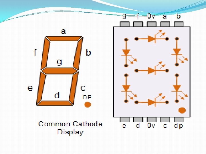
LED DISPLAYS §A 7 -segment LED display provides a very convenient way when decoded properly of displaying information or digital data in the form of numbers, letters or even alpha-numerical characters and as their name suggests, they consist of seven individual LEDs (the segments), within one single display package. § In order to produce the required numbers or characters from 0 to 9 and A to F respectively, on the display the correct combination of LED segments need to be illuminated.
LED DISPLAYS §A standard seven segment LED display generally has eight input connections, one for each LED segment and one that acts as a common terminal or connection for all the internal segments. § The Common Cathode Display (CCD): In the common cathode display, all the cathode connections of the LEDs are joined together and the individual segments are illuminated by application of a HIGH, logic “ 1” signal. §The Common Anode Display (CAD): In the common anode display, all the anode connections of the LEDs are joined together and the individual segments are illuminated by connecting the terminals to a LOW, logic “ 0” signal.
OPTO-COUPLER §Another useful application of light emitting diodes is Opto-coupling. §An opto-coupler or opto-isolator as it is also called, is a single electronic device that consists of a light emitting diode combined with either a photo-diode, phototransistor or photo-triac to provide an optical signal path between an input connection and an output connection while maintaining electrical isolation between two circuits.
OPTO-COUPLER §An opto-isolator consists of a light proof plastic body that has a typical breakdown voltages between the input (photo-diode) and the output (photo-transistor) circuit of up to 5000 volts. §This electrical isolation is especially useful where the signal from a low voltage circuit such as a battery powered circuit, computer or microcontroller, is required to operate or control another external circuit operating at a potentially dangerous mains voltage.
Photo-diode and Photo-transistor Optocouplers
OPTO-COUPLER §The two components used in an opto-isolator, an optical transmitter such as an infra-red emitting Gallium Arsenide LED and an optical receiver such as a photo-transistor are closely optically coupled and use light to send signals and/or information between its input and output. §This allows information to be transferred between circuits without an electrical connection or common ground potential. §Opto-isolators are digital or switching devices, so they transfer either “ON-OFF” control signals or digital data. Analogue signals can be transferred by means of frequency or pulse-width modulation.