Lifting Bodies for Subsonic Compressible Flows P M

Lifting Bodies for Subsonic Compressible Flows P M V Subbarao Professor Mechanical Engineering Department More Realistic Gas Dynamics of Steam and Gas Turbine Blades……

Innovative Mathematics close to the Reality • Is it correct to assume 2 =0 for all potential flows? ? ? • The potential theory learnt during few past lectures, is it truly a realistic model for steam and gas turbine blades? • Can we see an important positive characteristic of compressible flow is being missed in developing theory(earlier) of designing a lifting body ? !? !? !? • The real behavior of flow in steam and gas turbines is consider compressible subsonic flow through flow path and hence past a blade. • It is time to modify theory to model the practice.

Lifting Bodies in Subsonic Compressible Flows • The Velocity Potential function is also valid for compressible isentropic subsonic flows. From this velocity potential we can find the velocity components Continuity equation for steady 2 D compressible flow

2 -D Continuity Equation for Steady Compressible Flow

Prandtl-Glauert Concern • The hard work done for incompressible inviscid flow should not go waste. • It must be possible to apply with few modifications to incompressible potential flow theory to subsonic compressible flows. • How to estimate the degree of modification? • Any non-dimensional parameter, which can guide …? ? ?

Incompressible Flow Past A Body Viscous Boundary Layer V , T , p

Compressible Flow Past A Body V , T , p

Mach’s Supersonic Flows over Bodies

Speed of Travel of A Disturbance • The people had recognized for several hundred years that sound is a variation of pressure. • Mach generalized that, any body which generates pressure variation is a generator of disturbance(s). • The ears sense the variations by frequency and magnitude which are transferred to the brain which translates to voice. • Thus, it raises the question: what is the speed of the small disturbance travel in a quiet medium. • This velocity is referred to as the speed of sound. • Let us generate and analyze a disturbance.

Generation of Small Disturbance u u P+dp, r+dr. . . C p, r. . .

Disturbance as A Control Volume p, r. . . c-u P+dp, r+dr. . . C

Conservation Laws for an Invisicd Fluid

Conservation Laws Applied to 1 D Steady disturbance Conservation of Mass: Conservation of Mass for 1 DSF: p, r. . . c-u P+dp, r+dr. . . Change is final -initial C

For infinitesimally small disturbance Conservation of Momentum : For steady flow momentum equation for CV: For steady 1 -D flow :

Results of Conservation of Momentum Applied to CV of Infinitesimal Disturbance For infinitesimally small disturbance

Speed of sound perfect gases • Propagation of infinitesimal disturbance is considered as an isentropic process. • The speed of sound can be obtained easily for an ideal gas with constant properties because of a simple mathematical expression.

Steady disturbance in A Medium p, r. . . c-u P+dp, r+dr. . . C For a perfect gas:

Moving Disturbance In A Fluid • As an object moves through a fluid medium, it creates pressure waves. • Pressure waves travel out at the speed of sound which in term depends on gas properties and temperature. • If the object is traveling significantly slower than sonic velocity, then pressure waves travel out uniformly similar to waves on the surface of a pond.

Moving Disturbance In A Fluid • As the object approaches the speed of sound, it begins to catch up with the pressure waves and creates an infinitesimally weak flow discontinuity just ahead of the aircraft

Moving Disturbance In A Fluid • As the vehicle breaks the speed of sound, the infinitesimally weak Shock waves begin to add up along a “Mach Line” and form a strong pressure wave with highly compressed air, called a shockwave.

Mach’s Vision of Flow Modification by An Intrusion • As Mach number increases, the strength of the shock wave increases and the Angle of the shockwave becomes increasingly severe • Mach Angle

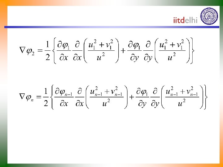
Velocity Potential for Compressible Flows Where, j 0 is incompressible flow solution.

The Linearized Velocity Potential Equation for Subsonic Compressible Flows For thin bodies at small angles of attack, based on few assumptions, the complicated equation reduces to This is the linearized perturbation velocity potential equation
 co-ordinates govern the incompressible potential")
Subsonic Compressible Flow A Laplacian equation in (x, y) co-ordinates govern the incompressible potential flow in physical plane. This equation in (x, y) co-ordinates govern the subsonic compressible potential flow in physical plane. A transformation function will convert in physical plane into in transformed plane into

Aerofoil in Z& planes This Laplacian equation will also govern the incompressible potential. Hence represents an incompressible flow in ( , ) space which is related to a compressible flow in the (x, y) space. Shape of the airfoil:

Prandtl-Glauert Rule • For subsonic flow past a blade at low angle of attack, the shape of streamlines in incompressible flow are similar to the streamlines in compressible flow. • The shape of zero streamline remain unchanged in incompressible to compressible flow past a blade. • What about effect? • Will the coefficient of pressure remain unchanged? • Will CL and CD remain unchanged?

Pressure Coefficient in incompressible flows • The pressure p may be found from Bernoulli’s equation. For an incompressible flow it is written as The velocity components in the flow influenced by the airfoil are represented in the form

Linearized Pressure Coefficient • For thin airfoils at low angle of attacks,

Linearized Pressure Coefficient Further, taking into account that the perturbation of the longitudinal velocity is related to the perturbation of the potential as The linearized pressure coefficient for incompressible flow past a Thin airfoil at low angles of attacks is: It was already shown that if the incompressible flow behavior is known, then there is no need to solve the compressible problem

Prandtl-Glauert rule • Following up with linearized pressure coefficient : Transformation model states that

The Final Outcome of Prandtl Glauert Rule Thus, it can be claimed that the pressure coefficient Cp at any point on a thin aerofoil surface in an compressible flow is (1 − M 2)− 1/2 times the pressure coefficient Cp 0 at the same point on the same aerofoil in incompressible flow. The thickness of the aerofoil in the subsonic compressible flow is times (1 − M 2)− 1/2 the thickness of the incompressible aerofoil These are called the final statements of Prandtl-Glauert rule.

The lift & Moment Coefficients

Validity of Prandtl Glauert Rule : NACA 4412

Improved Compressibility Corrections • The Prandtl-Glauert rule is based on the linearized velocity potential equation. • Other compressibility corrections do take the nonlinear terms into account. • Examples are the Karman-Tsien rule, which states that Laitone’s rule, stating that

Selection of Correct Formula for Cp Cp

Variable Mach Number Effect • The flow velocity is different on different positions on the blade. • Let the Mach number of the flow over our blade at a given point A be MA. • The corresponding pressure coefficient can then be found using

Local Mach Number Variations

Critical Mach Number • The velocity of the flow on top of our wing is generally higher than the free stream velocity V. • It may be possible to get sonic flow (M = 1) over the blade, while the upstream flow still at M < 1. • The critical Mach number Mcr is defined as the free stream Mach number M at which sonic flow (M = 1) is first achieved on the airfoil surface. • This is a very important value. • Define the critical pressure coefficient Cp, cr. • The relation between Mcr and Cp, cr can be found from the same equation.

Flow above Critical Mach Numbers

1930’s Flying Story Cruising at High Altitudes ? !? !? ! • Aircraft were trying to approach high altitudes for a better fuel economy. • This led to numerous crashes for unknown reasons. • These included: • The rapidly increasing forces on the various surfaces, which led to the aircraft becoming difficult to control to the point where many suffered from powered flight into terrain when the pilot was unable to overcome the force on the control stick. • The Mitsubishi Zero was infamous for this problem, and several attempts to fix it only made the problem worse. • In the case of the Super-marine Spitfire, the wings suffered from low torsional stiffness.

• The P-38 Lightning suffered from a particularly dangerous interaction of the airflow between the wings and tail surfaces in the dive that made it difficult to "pull out“. • Flutter due to the formation of thin high pressure line on curved surfaces was another major problem, which led most famously to the breakup of de Havilland Swallow and death of its pilot, Geoffrey de Havilland, Jr.
- Slides: 42