
Li DAR Fundamentals Part One L Monika Moskal


- Slides: 35
Li. DAR Fundamentals: Part One L. Monika Moskal, Ph. D Assistant Professor - Remote Sensing & Biospatial Analysis College of Forest Resources & Precision Forestry Cooperative University of Washington Workshop on Site-scale Applications of Li. DAR on Forest Lands in Washington Center for Urban Horticulture, UW Thursday, January 3, 2008
Li. DAR: What and Why? • Li. DAR stands for Light Detection and Ranging, commonly known as Laser Radar • Li. DAR is not only replacing conventional sensors, but also creating new methods with unique properties that could not be achieved before • Discrete Li. DAR
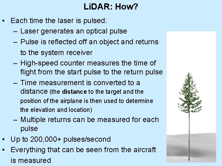
Li. DAR: How? • Each time the laser is pulsed: – Laser generates an optical pulse – Pulse is reflected off an object and returns to the system receiver – High-speed counter measures the time of flight from the start pulse to the return pulse – Time measurement is converted to a distance (the distance to the target and the position of the airplane is then used to determine the elevation and location) – Multiple returns can be measured for each pulse • Up to 200, 000+ pulses/second • Everything that can be seen from the aircraft is measured
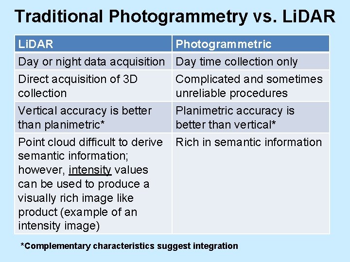
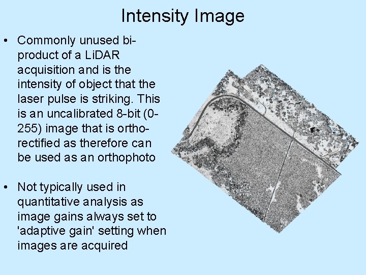
Traditional Photogrammetry vs. Li. DAR Day or night data acquisition Direct acquisition of 3 D collection Photogrammetric Day time collection only Complicated and sometimes unreliable procedures Vertical accuracy is better Planimetric accuracy is than planimetric* better than vertical* Point cloud difficult to derive Rich in semantic information; however, intensity values can be used to produce a visually rich image like product (example of an intensity image) *Complementary characteristics suggest integration
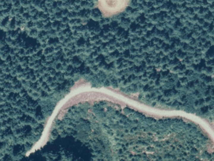
Intensity Image • Commonly unused biproduct of a Li. DAR acquisition and is the intensity of object that the laser pulse is striking. This is an uncalibrated 8 -bit (0255) image that is orthorectified as therefore can be used as an orthophoto • Not typically used in quantitative analysis as image gains always set to 'adaptive gain' setting when images are acquired
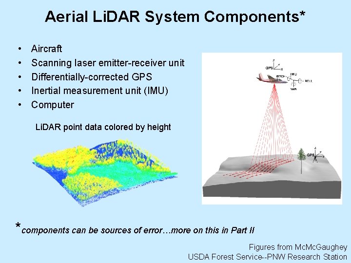
Aerial Li. DAR System Components* • • • Aircraft Scanning laser emitter-receiver unit Differentially-corrected GPS Inertial measurement unit (IMU) Computer Li. DAR point data colored by height *components can be sources of error…more on this in Part II Figures from Mc. Gaughey USDA Forest Service--PNW Research Station
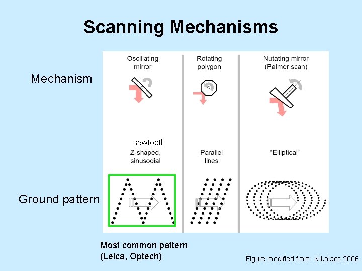
Scanning Mechanisms Mechanism sawtooth Ground pattern Most common pattern (Leica, Optech) Figure modified from: Nikolaos 2006
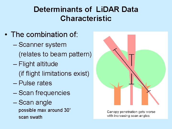
Determinants of Li. DAR Data Characteristic • The combination of: – Scanner system (relates to beam pattern) – Flight altitude (if flight limitations exist) – Pulse rates – Scan frequencies – Scan angle possible max around 30° scan swath
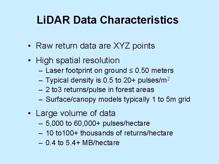
Li. DAR Data Characteristics • Raw return data are XYZ points • High spatial resolution – – Laser footprint on ground ≤ 0. 50 meters Typical density is 0. 5 to 20+ pulses/m 2 2 to 3 returns/pulse in forest areas Surface/canopy models typically 1 to 5 m grid • Large volume of data – 5, 000 to 60, 000+ pulses/hectare – 10 to 100+ thousands of returns/hectare – 0. 4 to 5. 4+ MB/hectare
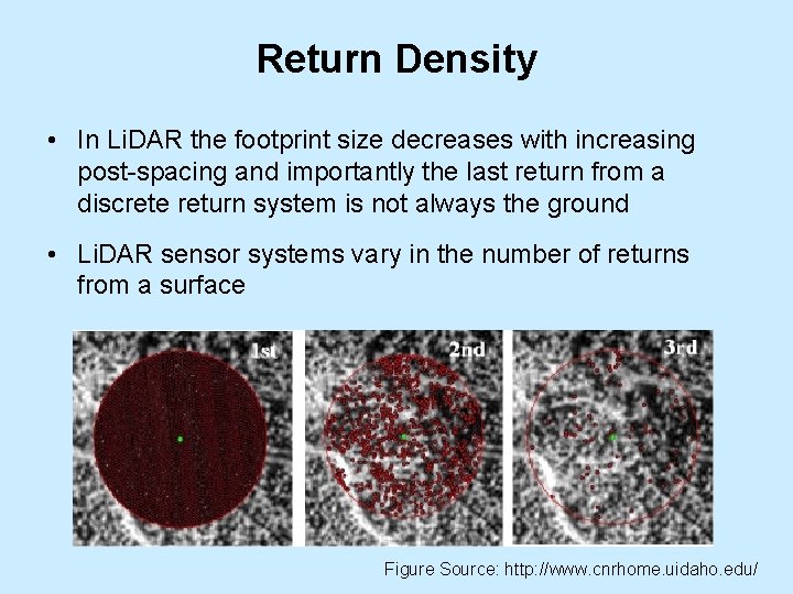
Return Density • In Li. DAR the footprint size decreases with increasing post-spacing and importantly the last return from a discrete return system is not always the ground • Li. DAR sensor systems vary in the number of returns from a surface Figure Source: http: //www. cnrhome. uidaho. edu/
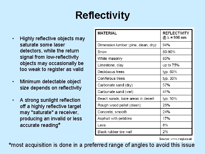
Reflectivity • Highly reflective objects may saturate some laser detectors, while the return signal from low-reflectivity objects may occasionally be too weak to register as valid • Minimum detectable object size depends on reflectivity • A strong sunlight reflection off a highly reflective target may "saturate" a receiver, producing an invalid or less accurate reading* *most acquisition is done in a preferred range of angles to avoid this issue
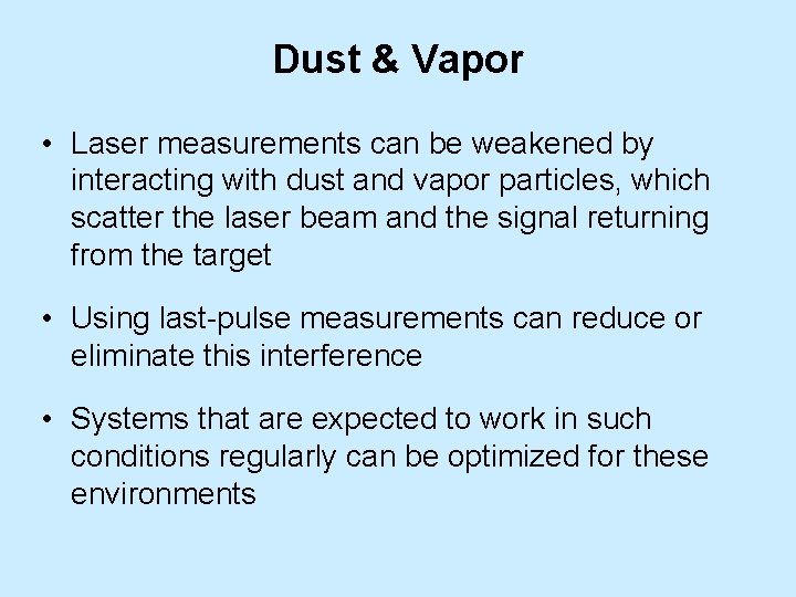
Dust & Vapor • Laser measurements can be weakened by interacting with dust and vapor particles, which scatter the laser beam and the signal returning from the target • Using last-pulse measurements can reduce or eliminate this interference • Systems that are expected to work in such conditions regularly can be optimized for these environments
Background Noise and Radiation • The laser is not affected by background noise • Most systems determine baseline radiation levels to ensure that it does not interfere with measurements
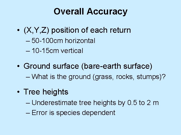
Overall Accuracy • (X, Y, Z) position of each return – 50 -100 cm horizontal – 10 -15 cm vertical • Ground surface (bare-earth surface) – What is the ground (grass, rocks, stumps)? • Tree heights – Underestimate tree heights by 0. 5 to 2 m – Error is species dependent
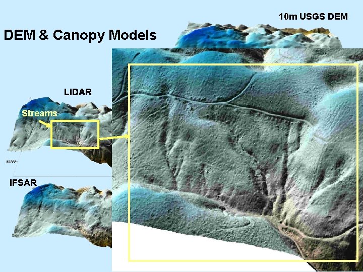
10 m USGS DEM & Canopy Models Li. DAR Streams Landslide IFSAR Li. DAR IFSAR
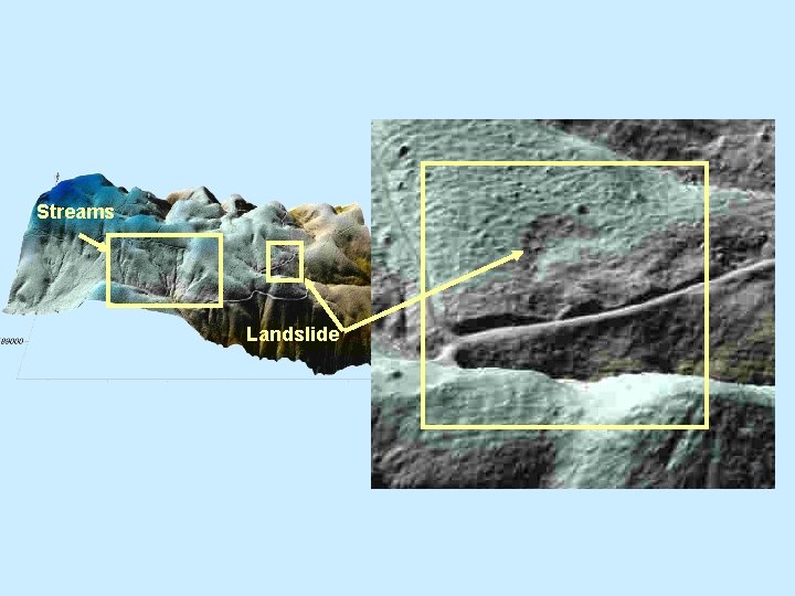
Streams Landslide
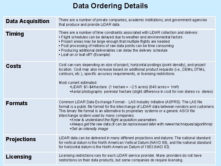
Data Ordering Details Data Acquisition There a number of private companies, academic institutions, and government agencies that produce and provide Li. DAR data. Timing There a number of time constraints associated with Li. DAR collection and delivery: • Flight schedules can be delayed due to weather and environmental factors • Project areas may be large enough that multiple flights are needed • Post processing of millions of raw data points can be time consuming • Producing additional deliverables can delay the delivery schedule • Leaf-on or leaf-off? (Example) Costs Cost can vary depending on size of project, horizontal postings (point density), and project location. Cost may also increase based on additional product requests (i. e. , DEMs, DTMs, contours, etc. ), specific accuracy requirements, or licensing restrictions. Most current estimated: • Li. DAR: $1 -$4/hectare (1 hectare = ~2. 5 acres) (640 acres = 1 mi 2) • Aerial photography: pennies/ hectare (slight difference in cost for non stereo vs. stereo) Formats Common Li. DAR Data Exchange Format -. LAS Industry Initiative (ASPRS). The LAS file format is a public file format for the interchange of Li. DAR data between vendors and customers. This binary file format is an alternative to proprietary systems or a generic ASCII file interchange system used by many companies. • Know & understand the flight acquisition parameters • Always get the raw data (it can be reprocessed later with newer techniques/algorithms) • Get an intensity image Projections Li. DAR data can be delivered in many different projections and datums. The national standard for vertical datum is the North American Vertical Datum (NAVD 88), and the national standard for horizontal datum is the North American Datum of 1983 (NAD 83). Licensing restrictions vary for each Li. DAR service provider. Many providers do not have restrictions on their data products, but some companies do require licensing.
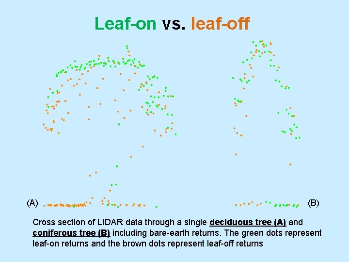
Leaf-on vs. leaf-off (A) (B) Cross section of LIDAR data through a single deciduous tree (A) and coniferous tree (B) including bare-earth returns. The green dots represent leaf-on returns and the brown dots represent leaf-off returns
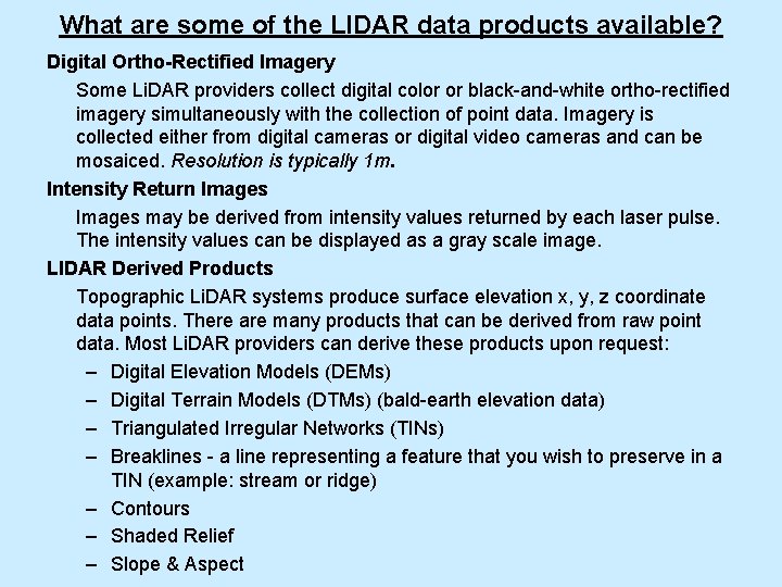
What are some of the LIDAR data products available? Digital Ortho-Rectified Imagery Some Li. DAR providers collect digital color or black-and-white ortho-rectified imagery simultaneously with the collection of point data. Imagery is collected either from digital cameras or digital video cameras and can be mosaiced. Resolution is typically 1 m. Intensity Return Images may be derived from intensity values returned by each laser pulse. The intensity values can be displayed as a gray scale image. LIDAR Derived Products Topographic Li. DAR systems produce surface elevation x, y, z coordinate data points. There are many products that can be derived from raw point data. Most Li. DAR providers can derive these products upon request: – Digital Elevation Models (DEMs) – Digital Terrain Models (DTMs) (bald-earth elevation data) – Triangulated Irregular Networks (TINs) – Breaklines - a line representing a feature that you wish to preserve in a TIN (example: stream or ridge) – Contours – Shaded Relief – Slope & Aspect
Li. DAR Fundamentals: Part Two L. Monika Moskal, Ph. D Assistant Professor - Remote Sensing & Biospatial Analysis College of Forest Resources & Precision Forestry Cooperative University of Washington Workshop on Site-scale Applications of Li. DAR on Forest Lands in Washington Center for Urban Horticulture, UW Thursday, January 3, 2008
Sources of Error • Acquisition • Processing – Strip adjustment – Selecting ground points – Thinning • Interpolation • Analysis/Visualization
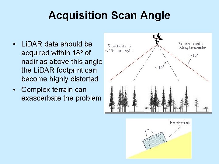
Acquisition Scan Angle • Li. DAR data should be acquired within 18º of nadir as above this angle the Li. DAR footprint can become highly distorted • Complex terrain can exascerbate the problem
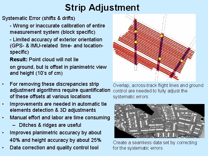
Strip Adjustment Systematic Error (shifts & drifts) - Wrong or inaccurate calibration of entire measurement system (block specific) - Limited accuracy of exterior orientation (GPS- & IMU-related time- and locationspecific) Result: Point cloud will not lie on ground, but is offset in planimetric view and height (10’s of cm) • • • For removing these discrepancies strip Overlap, across-track flight lines and ground adjustment algorithms require quantification control are needed to fully adjust the systematic errors of these offsets at various locations Improvements are needed in automatic tie elements detection & 3 D adjustments Manual effort and labor are time consuming – Ditches & ridges are useful Improves planimetric accuracy by about 40% and height accuracy by about 25% Create a seamless data set by correcting Data correction and quality control tool for the systematic errors
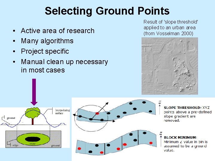
Selecting Ground Points • • Active area of research Many algorithms Project specific Manual clean up necessary in most cases Result of 'slope threshold' applied to an urban area (from Vosselman 2000)
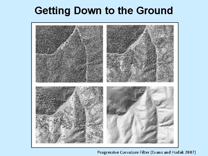
Getting Down to the Ground Progressive Curvature Filter (Evans and Hudak 2007)
Filtering • Post ground point selection filtering is also performed to reduce the size of the data sets • This type of filtering should only be applied in even terrain • Uneven terrain and densely vegetated areas are most susceptible to removal of critical interpolation points
Terrain • Digital elevation model (DEM), digital terrain model (DTM): “Ground” • Digital surface model (DSM): “top surface” • In open terrain, the separation surface between air and bare earth • DEM is different from measured laser points due to very different reasons: 1. 2. Filtering: classification of points into terrain and off-terrain Basis for DTM generation, detection of topographic objects
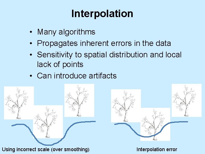
Interpolation • Many algorithms • Propagates inherent errors in the data • Sensitivity to spatial distribution and local lack of points • Can introduce artifacts Using incorrect scale (over smoothing) Interpolation error
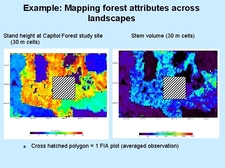
Example: Mapping forest attributes across landscapes Stand height at Capitol Forest study site (30 m cells) u Stem volume (30 m cells) Cross hatched polygon = 1 FIA plot (averaged observation)
Other Considerations • Li. DAR derived DEM are not often hydro-corrected so as to ensure a continuous downward flow of water (no Digital Line Graph (DLG) hypsographic and hydrographic data) • Water creates a natural void in Li. DAR data and manual addition of breadlines is necessary • This type of processing is feasible with Li. DAR data but it adds cost
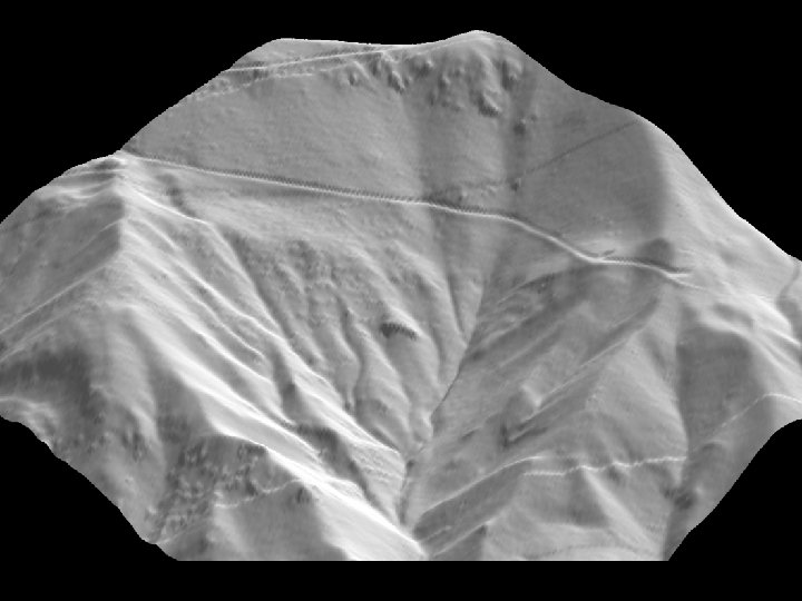
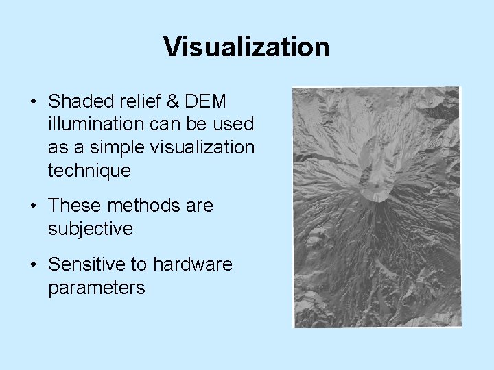
Visualization • Shaded relief & DEM illumination can be used as a simple visualization technique • These methods are subjective • Sensitive to hardware parameters
Further Analysis & Ground Validation • Once the DTM or DEM is available GIS can be utilized for further systematic analysis and modeling • Accuracy assessment should always be attempted (best approach is to do ground validation)