
LHCb VELO RF box upgrade an outlook q
LHCb VELO RF box upgrade: an outlook q Reminder: – what is VELO ? what is the RF box ? – why it is important for the LHC ? q q Status Planning / outlook Special thanks to Paula Collins & Wouter Hulsbergen for a number of slides LHC TREX 04 -Dec-2014 CERN Massimiliano Ferro-Luzzi 1
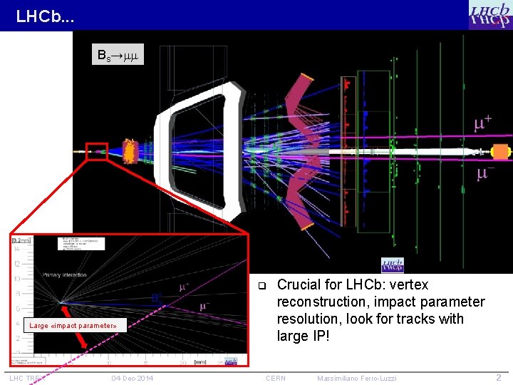
LHCb. . . Bs→ q Large «impact parameter» LHC TREX 04 -Dec-2014 Crucial for LHCb: vertex reconstruction, impact parameter resolution, look for tracks with large IP! CERN Massimiliano Ferro-Luzzi 2
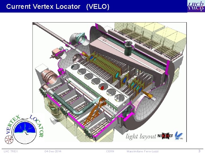
Current Vertex Locator (VELO) LHC TREX 04 -Dec-2014 CERN Massimiliano Ferro-Luzzi 3
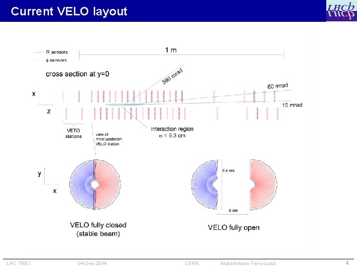
Current VELO layout LHC TREX 04 -Dec-2014 CERN Massimiliano Ferro-Luzzi 4
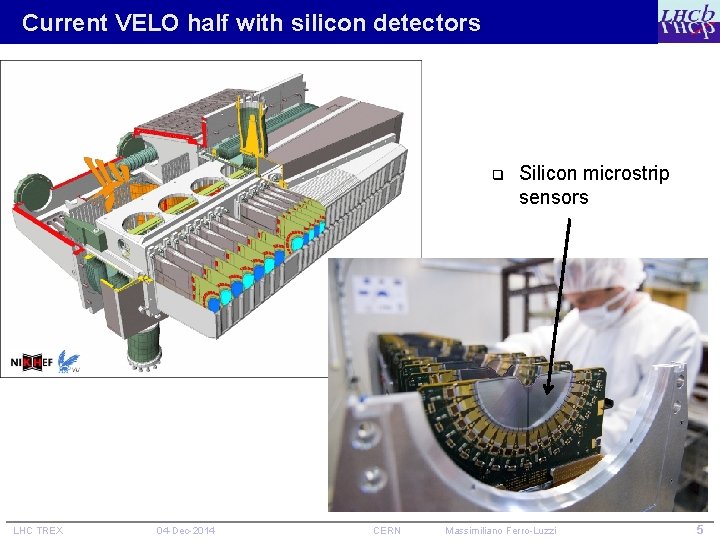
Current VELO half with silicon detectors q LHC TREX 04 -Dec-2014 CERN Silicon microstrip sensors Massimiliano Ferro-Luzzi 5
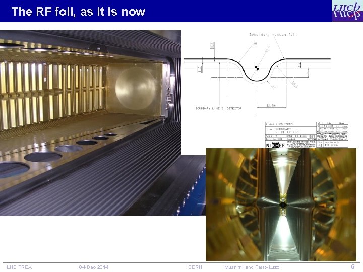
The RF foil, as it is now LHC TREX 04 -Dec-2014 CERN Massimiliano Ferro-Luzzi 6
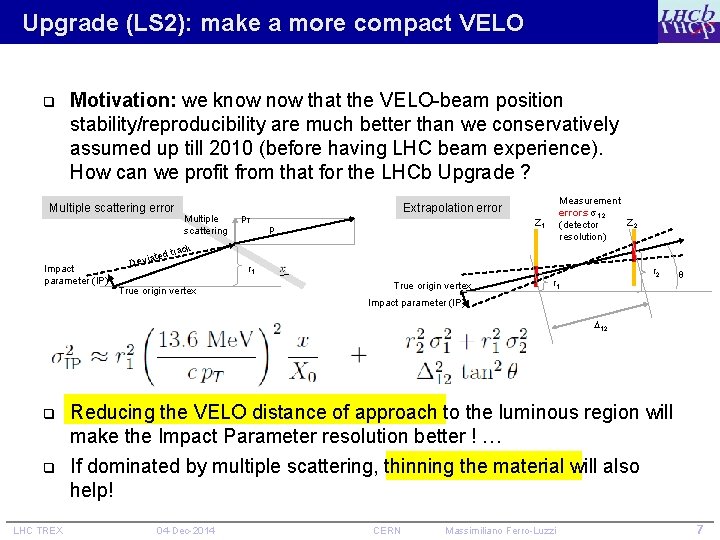
Upgrade (LS 2): make a more compact VELO q Motivation: we know that the VELO-beam position stability/reproducibility are much better than we conservatively assumed up till 2010 (before having LHC beam experience). How can we profit from that for the LHCb Upgrade ? Multiple scattering error Multiple scattering p. T Extrapolation error p Measurement errors 1, 2 Z 1 Z 2 (detector resolution) ack Impact parameter (IP) tr ated Devi True origin vertex r 1 True origin vertex r 2 r 1 Impact parameter (IP) 12 q q LHC TREX Reducing the VELO distance of approach to the luminous region will make the Impact Parameter resolution better ! … If dominated by multiple scattering, thinning the material will also help! 04 -Dec-2014 CERN Massimiliano Ferro-Luzzi 7
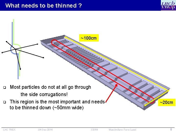
What needs to be thinned ? ~100 cm q Most particles do not at all go through the side corrugations! q This region is the most important and needs to be thinned down (~50 mm wide) LHC TREX 04 -Dec-2014 CERN ~20 cm Massimiliano Ferro-Luzzi 8
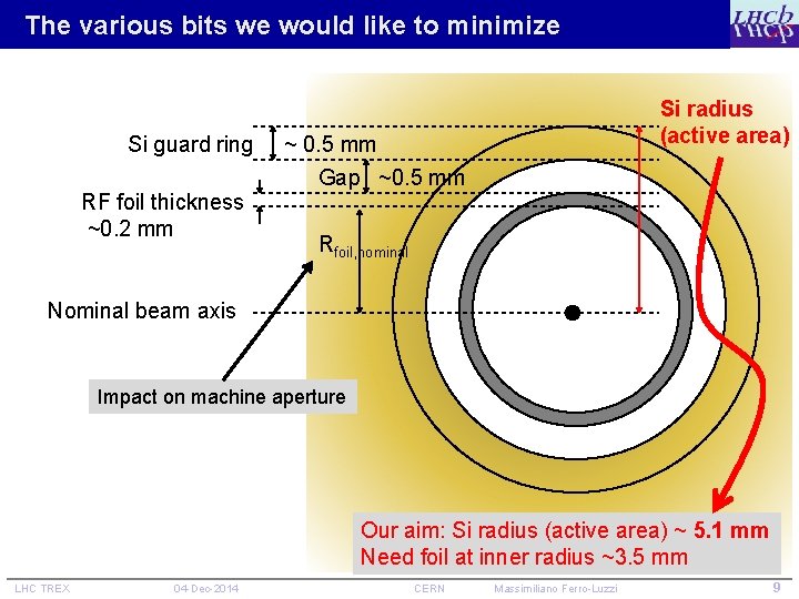
The various bits we would like to minimize Si radius (active area) Si guard ring ~ 0. 5 mm RF foil thickness ~0. 2 mm Gap ~0. 5 mm Rfoil, nominal Nominal beam axis Impact on machine aperture Our aim: Si radius (active area) ~ 5. 1 mm Need foil at inner radius ~3. 5 mm LHC TREX 04 -Dec-2014 CERN Massimiliano Ferro-Luzzi 9
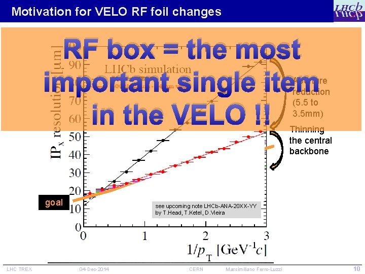
Motivation for VELO RF foil changes RF box = the most important single item in the VELO !! Aperture reduction (5. 5 to 3. 5 mm) Thinning the central backbone goal LHC TREX see upcoming note LHCb-ANA-20 XX-YY by T. Head, T. Ketel, D. Vieira 04 -Dec-2014 CERN Massimiliano Ferro-Luzzi 10
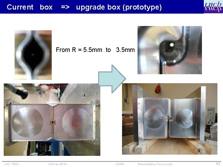
Current box => upgrade box (prototype) From R = 5. 5 mm to 3. 5 mm LHC TREX 04 -Dec-2014 CERN Massimiliano Ferro-Luzzi 11
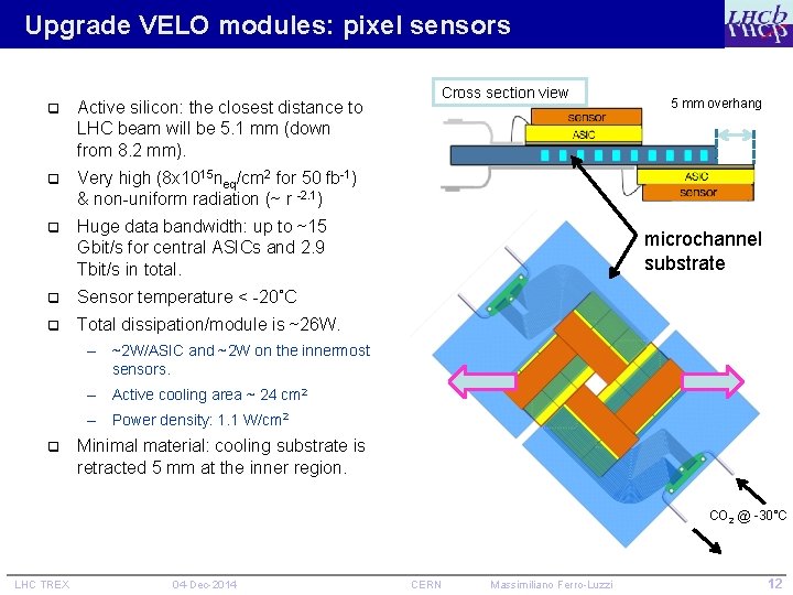
Upgrade VELO modules: pixel sensors q Active silicon: the closest distance to LHC beam will be 5. 1 mm (down from 8. 2 mm). q Very high (8 x 10¹⁵ neq/cm 2 for 50 fb-1) & non-uniform radiation (~ r -2. 1) q Huge data bandwidth: up to ~15 Gbit/s for central ASICs and 2. 9 Tbit/s in total. q Sensor temperature < -20˚C q Total dissipation/module is ~26 W. Cross section view 5 mm overhang microchannel substrate – ~2 W/ASIC and ~2 W on the innermost sensors. – Active cooling area ~ 24 cm 2 – Power density: 1. 1 W/cm 2 q Minimal material: cooling substrate is retracted 5 mm at the inner region. CO 2 @ -30˚C LHC TREX 04 -Dec-2014 CERN Massimiliano Ferro-Luzzi 12
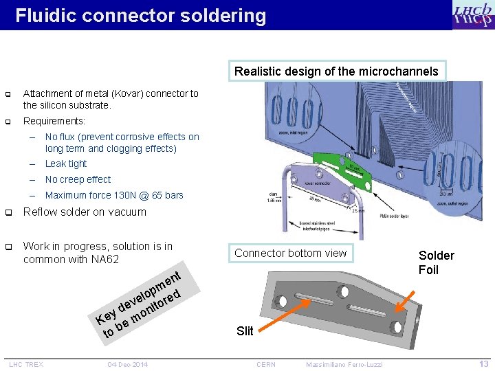
Fluidic connector soldering Realistic design of the microchannels q Attachment of metal (Kovar) connector to the silicon substrate. q Requirements: – No flux (prevent corrosive effects on long term and clogging effects) – Leak tight – No creep effect – Maximum force 130 N @ 65 bars q Reflow solder on vacuum q Work in progress, solution is in common with NA 62 nt e pm d o l ve itore e y d mon e K be to LHC TREX 04 -Dec-2014 Connector bottom view Solder Foil Slit CERN Massimiliano Ferro-Luzzi 13
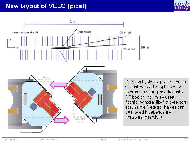
New layout of VELO (pixel) Rotation by 45° of pixel modules was introduced to optimize for tolerances during insertion into RF box and for more useful "partial retractability" of detectors at run time (detector halves can be moved independently in horizontal direction) LHC TREX 04 -Dec-2014 CERN Massimiliano Ferro-Luzzi 14
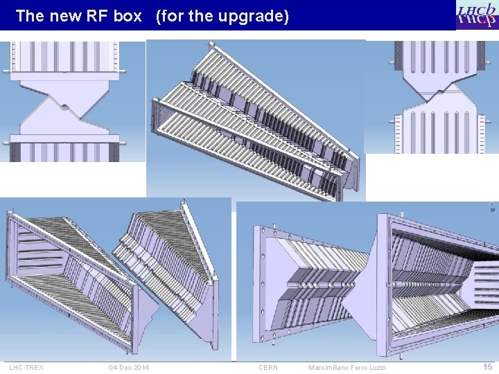
The new RF box (for the upgrade) LHC TREX 04 -Dec-2014 CERN Massimiliano Ferro-Luzzi 15
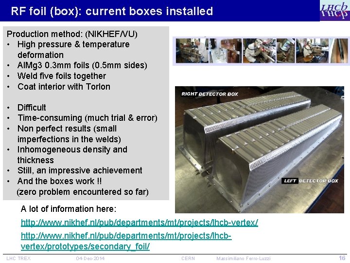
RF foil (box): current boxes installed Production method: (NIKHEF/VU) • High pressure & temperature deformation • Al. Mg 3 0. 3 mm foils (0. 5 mm sides) • Weld five foils together • Coat interior with Torlon • Difficult • Time-consuming (much trial & error) • Non perfect results (small imperfections in the welds) • Inhomogeneous density and thickness • Still, an impressive achievement • And the boxes work !! (zero problem encountered so far) A lot of information here: http: //www. nikhef. nl/pub/departments/mt/projects/lhcb-vertex/ http: //www. nikhef. nl/pub/departments/mt/projects/lhcbvertex/prototypes/secondary_foil/ LHC TREX 04 -Dec-2014 CERN Massimiliano Ferro-Luzzi 16
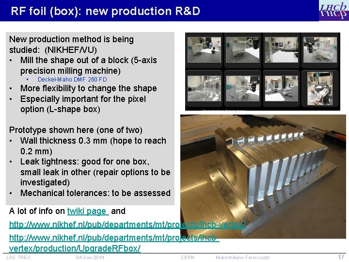
RF foil (box): new production R&D New production method is being studied: (NIKHEF/VU) • Mill the shape out of a block (5 -axis precision milling machine) • Deckel-Maho DMF 260 FD • More flexibility to change the shape • Especially important for the pixel option (L-shape box) Prototype shown here (one of two) • Wall thickness 0. 3 mm (hope to reach 0. 2 mm) • Leak tightness: good for one box, small leak in other (repair options to be investigated) • Mechanical tolerances: to be assessed A lot of info on twiki page and http: //www. nikhef. nl/pub/departments/mt/projects/lhcb-vertex/ http: //www. nikhef. nl/pub/departments/mt/projects/lhcbvertex/production/Upgrade. RFbox/ LHC TREX 04 -Dec-2014 CERN Massimiliano Ferro-Luzzi 17
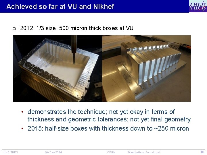
Achieved so far at VU and Nikhef q 2012: 1/3 size, 500 micron thick boxes at VU • demonstrates the technique; not yet okay in terms of thickness and geometric tolerances; not yet final geometry • 2015: half-size boxes with thickness down to ~250 micron LHC TREX 04 -Dec-2014 CERN Massimiliano Ferro-Luzzi 18
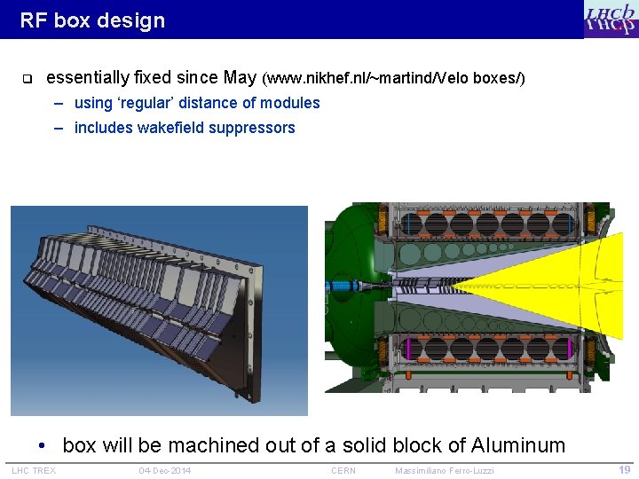
RF box design q essentially fixed since May (www. nikhef. nl/~martind/Velo boxes/) – using ‘regular’ distance of modules – includes wakefield suppressors • box will be machined out of a solid block of Aluminum LHC TREX 04 -Dec-2014 CERN Massimiliano Ferro-Luzzi 19
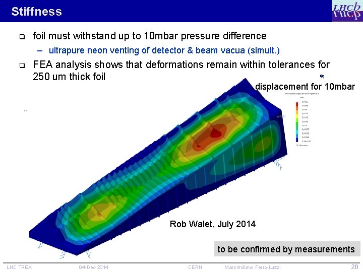
Stiffness q foil must withstand up to 10 mbar pressure difference – ultrapure neon venting of detector & beam vacua (simult. ) q FEA analysis shows that deformations remain within tolerances for 250 um thick foil displacement for 10 mbar Rob Walet, July 2014 to be confirmed by measurements LHC TREX 04 -Dec-2014 CERN Massimiliano Ferro-Luzzi 20
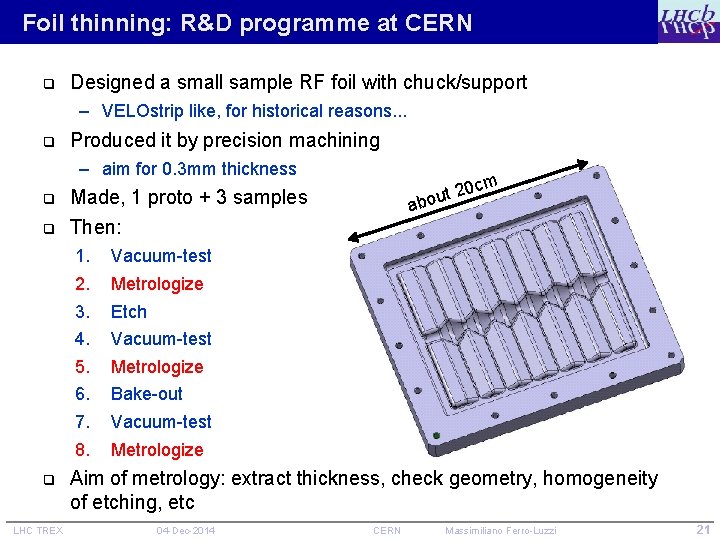
Foil thinning: R&D programme at CERN q Designed a small sample RF foil with chuck/support – VELOstrip like, for historical reasons. . . q Produced it by precision machining – aim for 0. 3 mm thickness q q Made, 1 proto + 3 samples Then: 1. 2. 3. 4. 5. 6. 7. 8. q LHC TREX cm 20 t u o ab Vacuum-test Metrologize Etch Vacuum-test Metrologize Bake-out Vacuum-test Metrologize Aim of metrology: extract thickness, check geometry, homogeneity of etching, etc 04 -Dec-2014 CERN Massimiliano Ferro-Luzzi 21
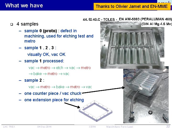
What we have q Thanks to Olivier Jamet and EN-MME 4 samples – sample 0 (proto) : defect in machining, used for etching test and metro – sample 1 , 2 , 3 : visually OK, vac OK – sample 1 processed: vac metro etch vac metro bake metro vac – sample 2 : vac metro bake metro vac – one counter piece / vac chuck – one extension piece for etching LHC TREX 04 -Dec-2014 CERN Massimiliano Ferro-Luzzi 22
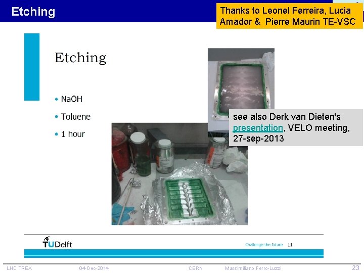
Etching Thanks to Leonel Ferreira, Lucia Amador & Pierre Maurin TE-VSC see also Derk van Dieten's presentation, VELO meeting, 27 -sep-2013 LHC TREX 04 -Dec-2014 CERN Massimiliano Ferro-Luzzi 23
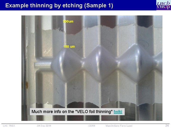
Example thinning by etching (Sample 1) 300 um 150 um Much more info on the "VELO foil thinning" twiki LHC TREX 04 -Dec-2014 CERN Massimiliano Ferro-Luzzi 24
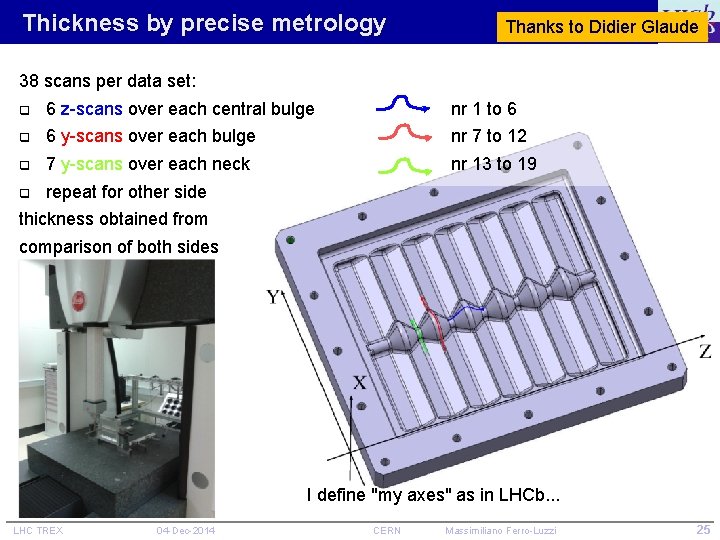
Thickness by precise metrology Thanks to Didier Glaude 38 scans per data set: q 6 z-scans over each central bulge nr 1 to 6 q 6 y-scans over each bulge nr 7 to 12 q 7 y-scans over each neck nr 13 to 19 q repeat for other side thickness obtained from comparison of both sides I define "my axes" as in LHCb. . . LHC TREX 04 -Dec-2014 CERN Massimiliano Ferro-Luzzi 25
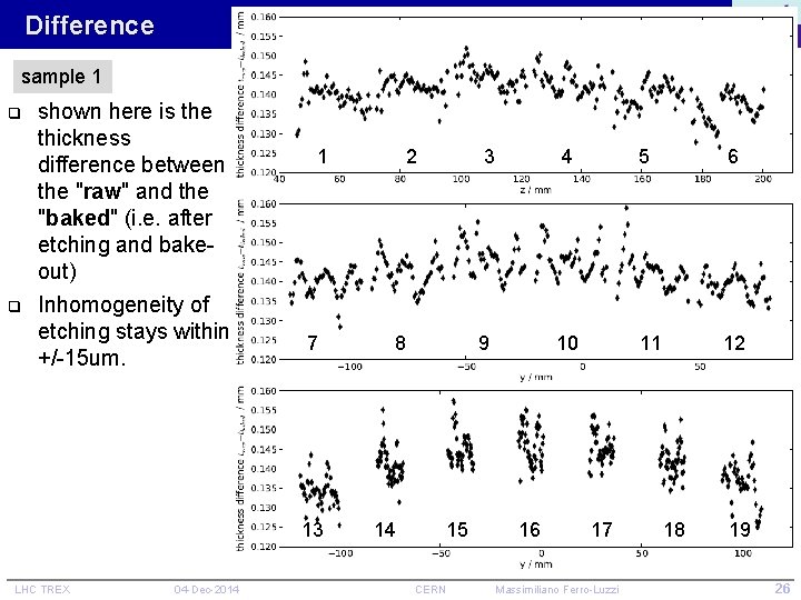
Difference sample 1 q q shown here is the thickness difference between the "raw" and the "baked" (i. e. after etching and bakeout) Inhomogeneity of etching stays within +/-15 um. 1 2 3 4 5 6 7 8 9 10 11 12 13 14 15 16 17 18 19 LHC TREX 04 -Dec-2014 CERN Massimiliano Ferro-Luzzi 26
RF box is not a piece of cake , or is it ? Just a few topics to keep an eye on: q Detector is cooled, in vacuum, and it's a movable device q Mechanical tolerances – gap of 0. 8 mm between foil and sensors – beam aperture of 3. 5 mm (RF foil) q Wakefields and impedance – RF pickup – heating – beam instabilities q Static and dynamic vacuum – beam-induced effects, NEG coating – ultrapure neon venting q LHC TREX Radiation 04 -Dec-2014 CERN Massimiliano Ferro-Luzzi 27
So what ? LHC TREX 04 -Dec-2014 CERN Massimiliano Ferro-Luzzi 28
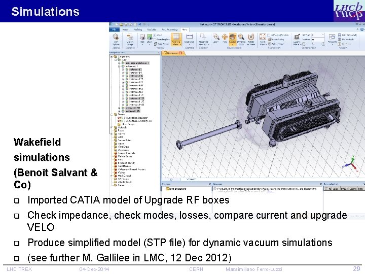
Simulations Wakefield simulations (Benoît Salvant & Co) q Imported CATIA model of Upgrade RF boxes q Check impedance, check modes, losses, compare current and upgrade VELO q Produce simplified model (STP file) for dynamic vacuum simulations q (see further M. Gallilee in LMC, 12 Dec 2012) LHC TREX 04 -Dec-2014 CERN Massimiliano Ferro-Luzzi 29
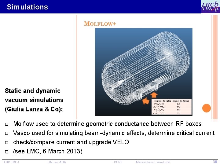
Simulations Static and dynamic vacuum simulations (Giulia Lanza & Co): q q Molflow used to determine geometric conductance between RF boxes Vasco used for simulating beam-dynamic effects, determine critical current check/compare current and upgrade VELO (see LMC, 6 March 2013) LHC TREX 04 -Dec-2014 CERN Massimiliano Ferro-Luzzi 30
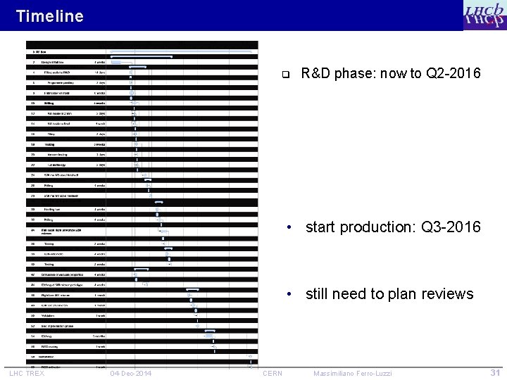
Timeline q R&D phase: now to Q 2 -2016 • start production: Q 3 -2016 • still need to plan reviews LHC TREX 04 -Dec-2014 CERN Massimiliano Ferro-Luzzi 31
Standard monitoring of developments q q Current VELO: interface issues discussed in the past in LEMIC Upgrade VELO: interface issues discussed in the past within LEB working group (+ PLC and LMC), now TREX Propose to have q a workshop dedicated to RF box on 5 -6 Feb 2015 at CERN – preliminary results of WF and dynvac simulations – production results from first half-size 500 um box – recap of all aspects of the RF box integration in the machine => help from Mark Gallilee to contact key people at CERN (TE-VSC, ENMME, BE-ABP, . . . ), find a suitable room, etc. q detailed reviews to be agreed upon, to come later – EDR in Q 3 -4 2015, after the half-sized prototypes, or later (? ) – PRR in Q 1 -2 2016 after prototyping, before production (? ) LHC TREX 04 -Dec-2014 CERN Massimiliano Ferro-Luzzi 32
Summary and conclusions q q VELO RF box is a key item for LHCb & LHCb Upgrade Successful so far, great performance in Run 1 – we will learn more through Run 2 q New shape and reduced aperture for Upgrade (LS 2) – else, quite the same as now q Cooperation between LHCb & LHC has been and will be essential for success of RF boxes in the LHCb/VELO upgrade – wakefield simulations – static & dynamic vacuum simulations – metallurgy expertise, NEG coating, etching, . . . q RF box production strategy is new (machined out of a block) – first developments atre promising, but still a lot to prove q LHC TREX Development of RF boxes enters a new phase (detector geometry is now frozen since a few months), last chance to fine-tune => workshop comes in timely (5 -6 Feb 2015) 04 -Dec-2014 CERN Massimiliano Ferro-Luzzi 33
LHC TREX 04 -Dec-2014 CERN Massimiliano Ferro-Luzzi 34
extra slides LHC TREX 04 -Dec-2014 CERN Massimiliano Ferro-Luzzi 35
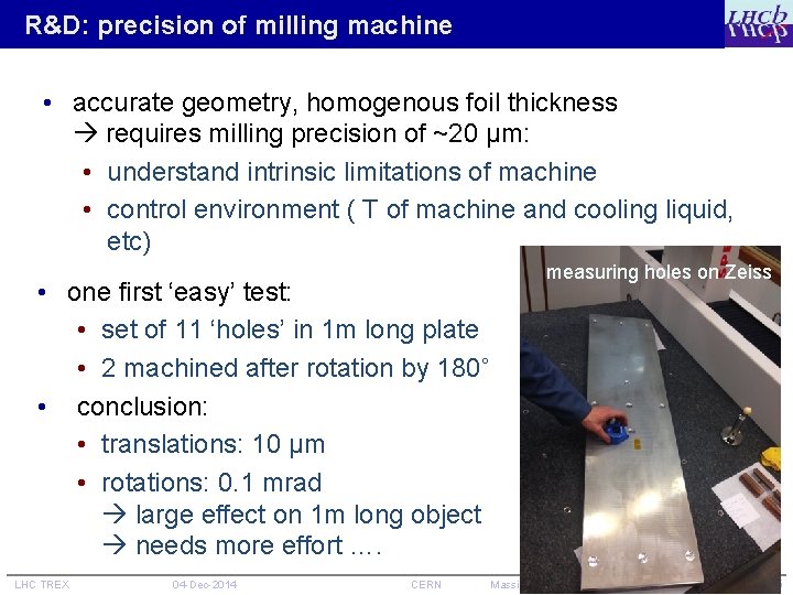
R&D: precision of milling machine • accurate geometry, homogenous foil thickness requires milling precision of ~20 μm: • understand intrinsic limitations of machine • control environment ( T of machine and cooling liquid, etc) • one first ‘easy’ test: • set of 11 ‘holes’ in 1 m long plate • 2 machined after rotation by 180˚ • conclusion: • translations: 10 μm • rotations: 0. 1 mrad large effect on 1 m long object needs more effort …. LHC TREX 04 -Dec-2014 CERN measuring holes on Zeiss Massimiliano Ferro-Luzzi 36
R&D: filling q cannot ‘machine’ a 500 micron foil w/o supporting it q small prototypes were built using Al mold – requires extreme accuracy to get tight fit – do not think we can do that for a 1 m long box q current strategy: Al mold + filling – use mold that leaves about 1 mm between foil and mold – fill remainder up with something that is solid at 20 degrees, but melts at relatively low temperature – we experiment both with Wood’s metals (Field’s metal, Cerrolow 136) and with a synthetic wax § first test show that wax is probably fine (and easier) LHC TREX 04 -Dec-2014 CERN Massimiliano Ferro-Luzzi 37
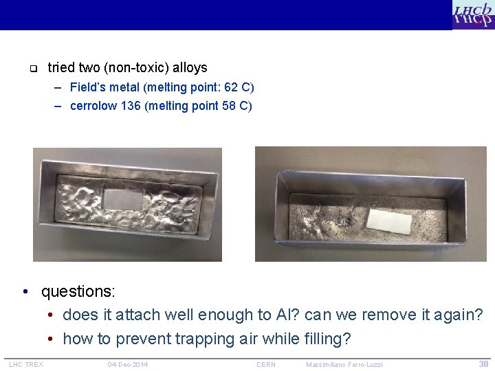
q tried two (non-toxic) alloys – Field’s metal (melting point: 62 C) – cerrolow 136 (melting point 58 C) • questions: • does it attach well enough to Al? can we remove it again? • how to prevent trapping air while filling? LHC TREX 04 -Dec-2014 CERN Massimiliano Ferro-Luzzi 38
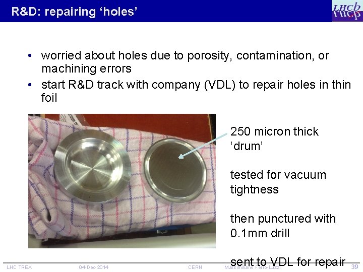
R&D: repairing ‘holes’ • worried about holes due to porosity, contamination, or machining errors • start R&D track with company (VDL) to repair holes in thin foil 250 micron thick ‘drum’ tested for vacuum tightness then punctured with 0. 1 mm drill LHC TREX 04 -Dec-2014 CERN sent to VDL for repair 39 Massimiliano Ferro-Luzzi
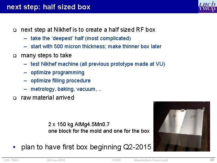
next step: half sized box q next step at Nikhef is to create a half sized RF box – take the ‘deepest’ half (most complicated) – start with 500 micron thickness; make thinner box later q many steps to take – – q test Nikhef machine (all previous prototype made at VU) optimize programming optimize filling procedure metrology, baking, vacuum, . . raw material arrived 2 x 150 kg Al. Mg 4. 5 Mn 0. 7 one block for the mold and one for the box • plan to have first box beginning Q 2 -2015 LHC TREX 04 -Dec-2014 CERN Massimiliano Ferro-Luzzi 40
a topic for discussion q drawings are made for 250 micron suppose that we make a thin and a thick section in the foil q which side do we make thicker? q – velo side? rather not, because we cannot get closer to the sensors! – vacuum side? LHC TREX 04 -Dec-2014 CERN Massimiliano Ferro-Luzzi 41
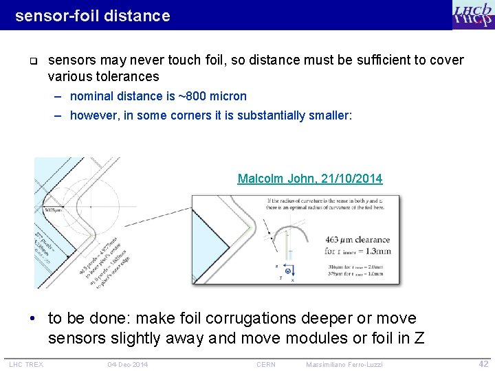
sensor-foil distance q sensors may never touch foil, so distance must be sufficient to cover various tolerances – nominal distance is ~800 micron – however, in some corners it is substantially smaller: Malcolm John, 21/10/2014 • to be done: make foil corrugations deeper or move sensors slightly away and move modules or foil in Z LHC TREX 04 -Dec-2014 CERN Massimiliano Ferro-Luzzi 42
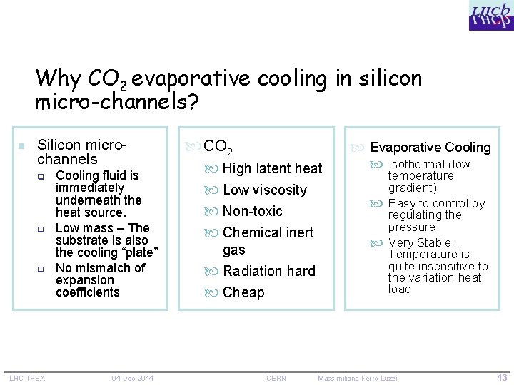
Why CO 2 evaporative cooling in silicon micro-channels? n Silicon microchannels q q q LHC TREX Cooling fluid is immediately underneath the heat source. Low mass – The substrate is also the cooling “plate” No mismatch of expansion coefficients 04 -Dec-2014 CO 2 Evaporative Cooling High latent heat Low viscosity Non-toxic Chemical inert gas Radiation hard Cheap CERN Isothermal (low temperature gradient) Easy to control by regulating the pressure Very Stable: Temperature is quite insensitive to the variation heat load Massimiliano Ferro-Luzzi 43
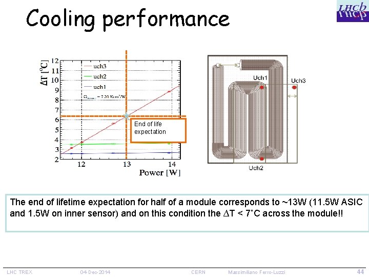
Cooling performance End of life expectation The end of lifetime expectation for half of a module corresponds to ~13 W (11. 5 W ASIC and 1. 5 W on inner sensor) and on this condition the ∆T < 7˚C across the module!! LHC TREX 04 -Dec-2014 CERN Massimiliano Ferro-Luzzi 44
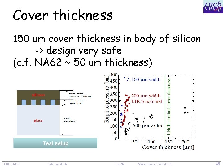
Cover thickness 150 um cover thickness in body of silicon -> design very safe (c. f. NA 62 ~ 50 um thickness) Test setup LHC TREX 04 -Dec-2014 CERN Massimiliano Ferro-Luzzi 45
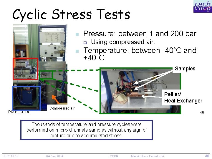
Cyclic Stress Tests n Pressure: between 1 and 200 bar q n Using compressed air. Temperature: between -40˚C and +40˚C Samples Peltier/ Heat Exchanger PIXEL 2014 Compressed air 04/09/14 46 Thousands of temperature and pressure cycles were performed on micro-channels samples without any sign of rupture due to accumulated stress. LHC TREX 04 -Dec-2014 CERN Massimiliano Ferro-Luzzi 46
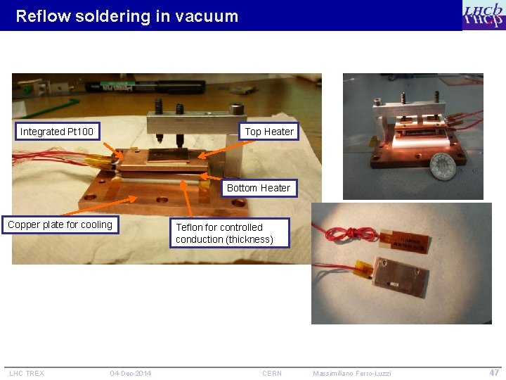
Reflow soldering in vacuum Integrated Pt 100 Top Heater Bottom Heater Copper plate for cooling LHC TREX 04 -Dec-2014 Teflon for controlled conduction (thickness) CERN Massimiliano Ferro-Luzzi 47
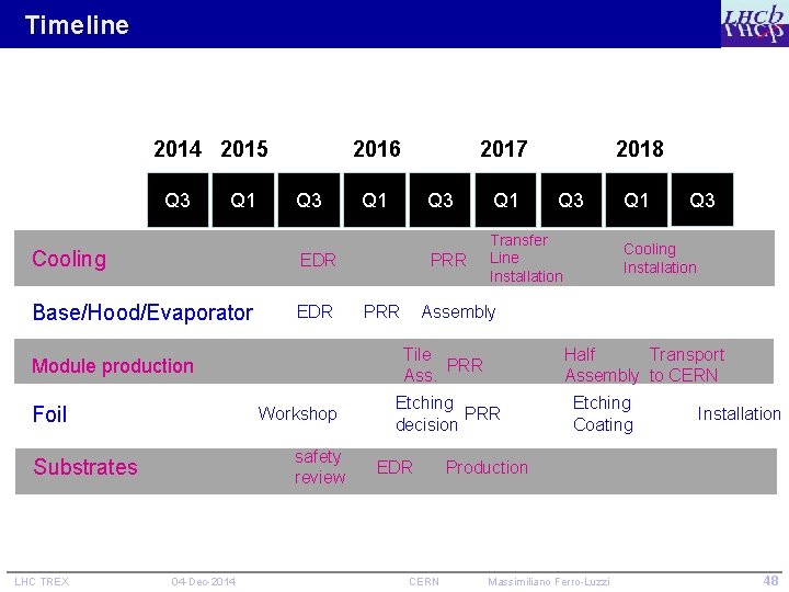
Timeline 2014 2015 Q 3 Q 1 2016 Q 3 Cooling EDR Base/Hood/Evaporator EDR Workshop safety review Substrates LHC TREX 04 -Dec-2014 Q 1 PRR 2018 Q 3 Q 1 PRR Transfer Line Installation Q 3 Q 1 Q 3 Cooling Installation Assembly Tile PRR Ass. Module production Foil 2017 Half Transport Assembly to CERN Etching PRR decision EDR CERN Etching Coating Installation Production Massimiliano Ferro-Luzzi 48
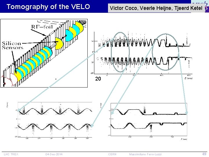
Tomography of the VELO Victor Coco, Veerle Heijne, Tjeerd Ketel 20 LHC TREX 04 -Dec-2014 CERN Massimiliano Ferro-Luzzi 49
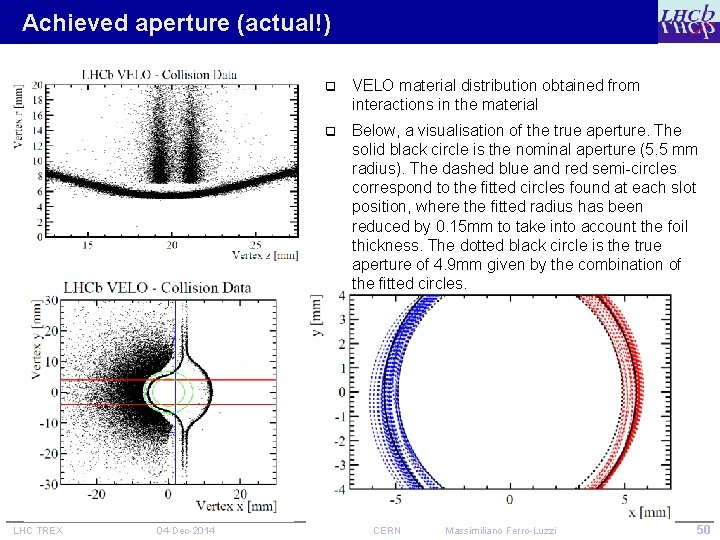
Achieved aperture (actual!) LHC TREX 04 -Dec-2014 q VELO material distribution obtained from interactions in the material q Below, a visualisation of the true aperture. The solid black circle is the nominal aperture (5. 5 mm radius). The dashed blue and red semi-circles correspond to the fitted circles found at each slot position, where the fitted radius has been reduced by 0. 15 mm to take into account the foil thickness. The dotted black circle is the true aperture of 4. 9 mm given by the combination of the fitted circles. CERN Massimiliano Ferro-Luzzi 50
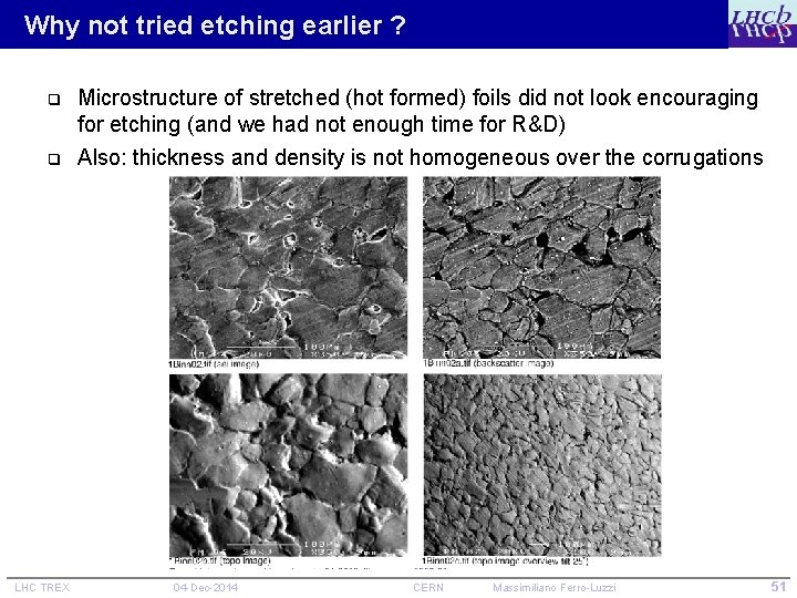
Why not tried etching earlier ? q Microstructure of stretched (hot formed) foils did not look encouraging for etching (and we had not enough time for R&D) q Also: thickness and density is not homogeneous over the corrugations LHC TREX 04 -Dec-2014 CERN Massimiliano Ferro-Luzzi 51
- Slides: 51