
LHCb Online event processing and filtering Niko Neufeld
LHCb Online event processing and filtering Niko Neufeld, CERN/PH on behalf of the LHCb Online Team LHCb Online event processing and filtering
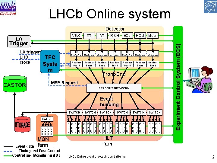
LHCb Online system L 0 Trigger L 0 trigger LHC clock TFC Syste m VELO ST OT RICH ECal HCal Muon FE Electronics FE Electronics Readout Board Readout Board Front-End MEP Request CASTOR READOUT NETWORK Event building SWITCH SWITCH C C C C P P P P U U U U CC C C PP P P UU U U SWITCH CC C C P P UU U U MON farm Event data Timing and Fast Control and Signals Monitoring data C C P P U U Experiment Control System (ECS) Detector HLT farm LHCb Online event processing and filtering 2
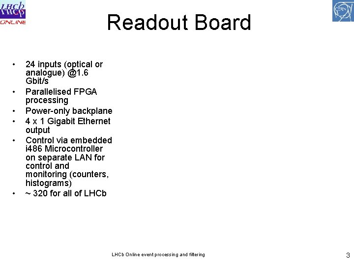
Readout Board • • • 24 inputs (optical or analogue) @1. 6 Gbit/s Parallelised FPGA processing Power-only backplane 4 x 1 Gigabit Ethernet output Control via embedded i 486 Microcontroller on separate LAN for control and monitoring (counters, histograms) ~ 320 for all of LHCb Online event processing and filtering 3

Protocols & Architecture • Design principle: simplicity – limit the number of protocols and technologies • FPGA based Readout Boards are directly attached to Gigabit Ethernet DAQ network – simple datagram protocol: MEP over IPv 4 • well suited for implementation in FPGAs – no re-transmission – no buffering • no back-traffic – can use over-commited router-ports (to some extent) • MEP: collects several triggers into one packet reduces overhead (average event fragment ~ 120 Bytes only / overhead on IP/Ethernet is 58 Bytes • TCP/IP for all data out of the event filter farm • DIM for information exchange in controls and monitoring (histograms, counters) • GRIDftp for data transfer to Tier 0 (used in LHCb via DIRAC) LHCb Online event processing and filtering 4
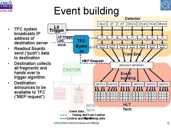
Event building • • Detector VELO ST OT RICH ECal HCal Muon FE Electronics FE Electronics Readout Board Readout Board L 0 TFC system Trigger broadcasts IP L 0 trigger address of LHC TFC destination server Readout clock Syste Board Readout Boards m send (“push”) data to destination MEP Request Destination collects all fragments and CASTOR hands over to trigger algorithm Destination SWITCH announces to be SWITCH available to TFC C C P P CC CC (“MEP request”) PP PP U U UU UU MON farm Event data Timing and Fast Control and Signals Monitoring data LHCb Online event processing and filtering Front-End READOUT NETWORK Event building SWITCH SWITCH C C C C P P P P U U U U CC C C PP P P UU U U HLT farm 5
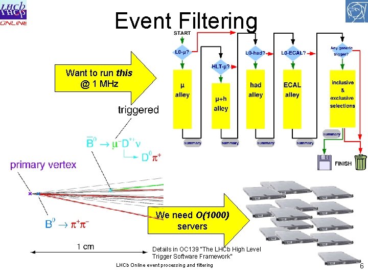
Event Filtering Want to run this @ 1 MHz We need O(1000) servers Details in OC 139 “The LHCb High Level Trigger Software Framework” LHCb Online event processing and filtering 6
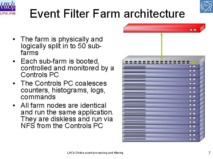
Event Filter Farm architecture • The farm is physically and logically split in to 50 subfarms • Each sub-farm is booted, controlled and monitored by a Controls PC • The Controls PC coalesces counters, histograms, logs, commands • All farm nodes are identical and run the same application. They are diskless and run via NFS from the Controls PC LHCb Online event processing and filtering 7
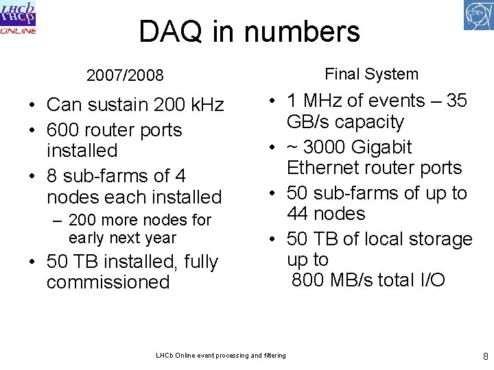
DAQ in numbers 2007/2008 Final System • Can sustain 200 k. Hz • 600 router ports installed • 8 sub-farms of 4 nodes each installed • 1 MHz of events – 35 GB/s capacity • ~ 3000 Gigabit Ethernet router ports • 50 sub-farms of up to 44 nodes • 50 TB of local storage up to 800 MB/s total I/O – 200 more nodes for early next year • 50 TB installed, fully commissioned LHCb Online event processing and filtering 8
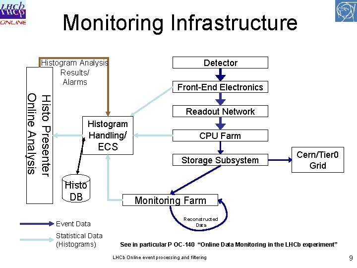
Monitoring Infrastructure Detector Histogram Analysis Results/ Alarms Front-End Electronics Histo Presenter Online Analysis Readout Network Histogram Handling/ CPU Farm ECS Storage Subsystem Histo DB Event Data Statistical Data (Histograms) Cern/Tier 0 Grid Monitoring Farm Reconstructed Data See in particular P OC-140 “Online Data Monitoring in the LHCb experiment” LHCb Online event processing and filtering 9
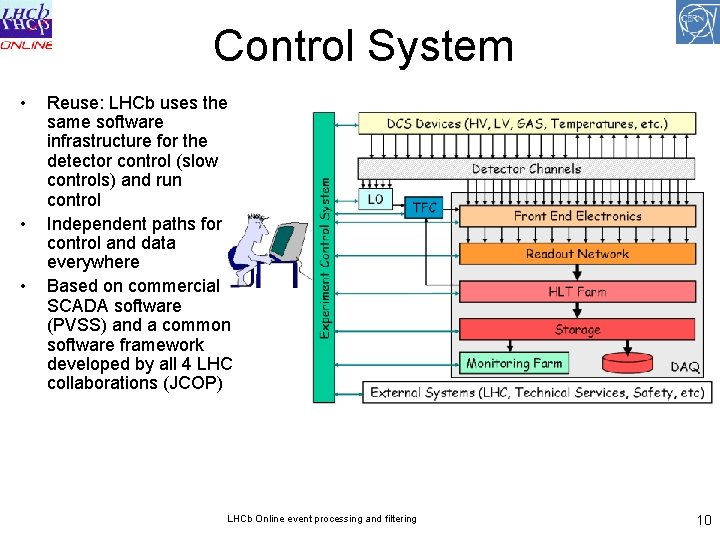
Control System • • • Reuse: LHCb uses the same software infrastructure for the detector control (slow controls) and run control Independent paths for control and data everywhere Based on commercial SCADA software (PVSS) and a common software framework developed by all 4 LHC collaborations (JCOP) LHCb Online event processing and filtering 10
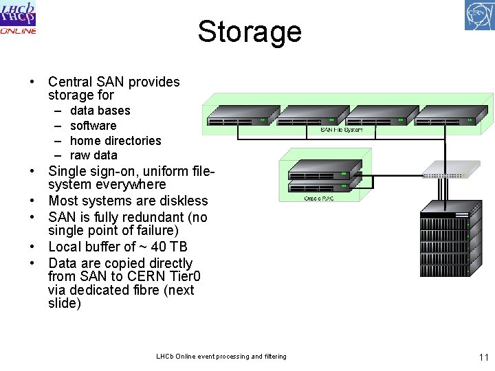
Storage • Central SAN provides storage for – – data bases software home directories raw data • Single sign-on, uniform filesystem everywhere • Most systems are diskless • SAN is fully redundant (no single point of failure) • Local buffer of ~ 40 TB • Data are copied directly from SAN to CERN Tier 0 via dedicated fibre (next slide) LHCb Online event processing and filtering 11
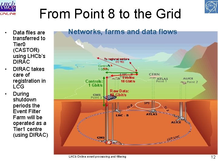
From Point 8 to the Grid • • • Data files are transferred to Tier 0 (CASTOR) using LHCb’s DIRAC takes care of registration in LCG During shutdown periods the Event Filter Farm will be operated as a Tier 1 centre (using DIRAC) Networks, farms and data flows To regional centers OC 192 Controls: 1 Gbit/s Events: 10 Gbit/s Raw Data: 10 Gbit/s LHCb Online event processing and filtering 12
Conclusion • Event processing in LHCb is done mostly on commercial commodity hardware (IA 32, Gigabit Ethernet) • Monitoring is implemented at all stages using a dedicated infrastructure, reusing as much as possible existing frameworks • The architecture is scalable – information and control is coalesced at every layer • Standard tools / technologies from other fields are used wherever possible: DIRAC/Grid for data transfer, PVSS/SCADA for run-control • Base system is deployed and running: remaining hardware will be bought and installed in sync with the LHC schedule LHCb Online event processing and filtering 13
- Slides: 13