
Lesson 8et 332 b pptx 1 LESSON 8
Lesson 8_et 332 b. pptx 1 LESSON 8: IDEAL TRANSFORMER THEORY AND OPERATION ET 332 b Ac Motors, Generators and Power Systems
Learning Objectives 2 After this presentation you will be able to: Ø Ø Ø Explain how an ideal transformer operates Find the voltages and currents on both sides of an ideal transformer using the turns ration Reflect impedances through a transformer Identify and compute the no-load currents that flow in a non-ideal transformer Draw the no-load circuit model of a non-ideal transformer. Lesson 8_et 332 b. pptx
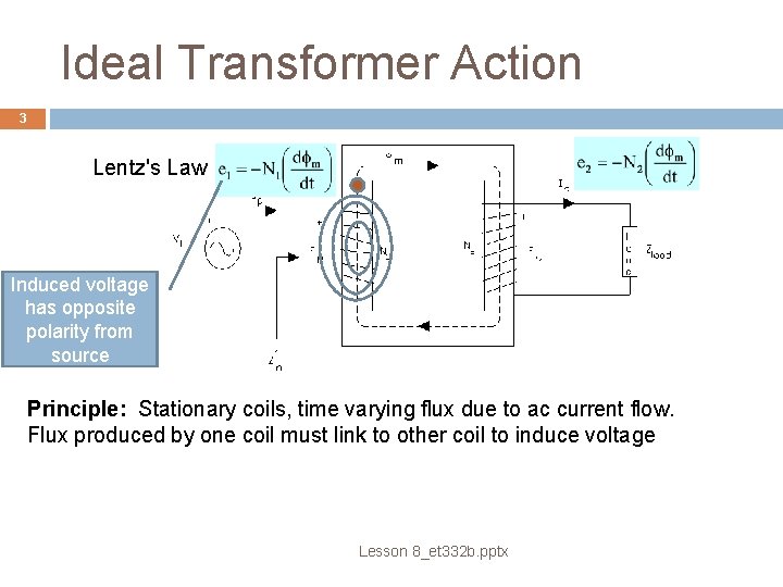
Ideal Transformer Action 3 Lentz's Law Induced voltage has opposite polarity from source Principle: Stationary coils, time varying flux due to ac current flow. Flux produced by one coil must link to other coil to induce voltage Lesson 8_et 332 b. pptx
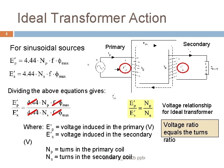
Ideal Transformer Action 4 For sinusoidal sources Primary Secondary Dividing the above equations gives: Voltage relationship for Ideal transformer Where: E’p = voltage induced in the primary (V) E’s = voltage induced in the secondary (V) Np = turns in the primary coil Ns = turns in the secondary coil Lesson 8_et 332 b. pptx Voltage ratio equals the turns ratio
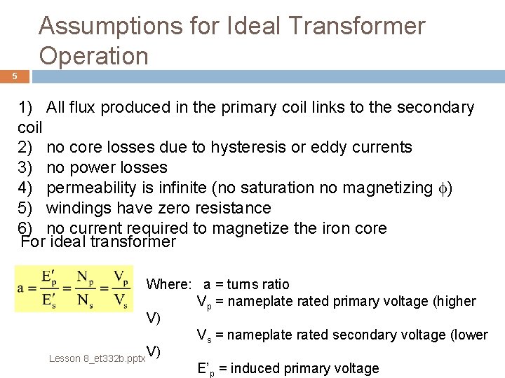
Assumptions for Ideal Transformer Operation 5 1) All flux produced in the primary coil links to the secondary coil 2) no core losses due to hysteresis or eddy currents 3) no power losses 4) permeability is infinite (no saturation no magnetizing f) 5) windings have zero resistance 6) no current required to magnetize the iron core For ideal transformer Where: a = turns ratio Vp = nameplate rated primary voltage (higher V) Vs = nameplate rated secondary voltage (lower V) Lesson 8_et 332 b. pptx E’p = induced primary voltage
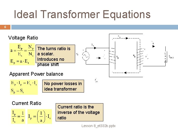
Ideal Transformer Equations 6 Voltage Ratio The turns ratio is a scalar. Introduces no phase shift Apparent Power balance No power losses in idea transformer Current Ratio Current ratio is the inverse of the voltage ratio Lesson 8_et 332 b. pptx
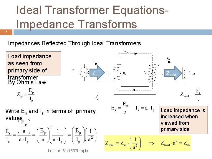
7 Ideal Transformer Equations. Impedance Transforms Impedances Reflected Through Ideal Transformers Load impedance as seen from primary side of transformer By Ohm’s Law Zin Write Es and Is in terms of primary values Lesson 8_et 332 b. pptx Zload Load impedance is increased when viewed from primary side

8 Ideal Transformer Equations. Impedance Transforms Derive equation when impedances are connected to the primary side and viewed from the secondary side. Write primary values in terms of secondary and substitute in the Zload equation. Zload Zin Generally : Moving impedance from secondary to primary multiply by a 2. Moving from primary to secondary, divide by a 2. Lesson 8_et 332 b. pptx
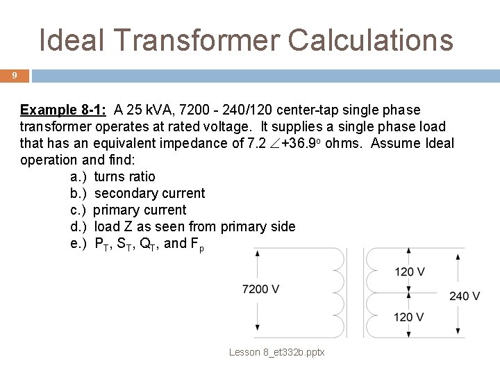
Ideal Transformer Calculations 9 Example 8 -1: A 25 k. VA, 7200 - 240/120 center-tap single phase transformer operates at rated voltage. It supplies a single phase load that has an equivalent impedance of 7. 2 +36. 9 o ohms. Assume Ideal operation and find: a. ) turns ratio b. ) secondary current c. ) primary current d. ) load Z as seen from primary side e. ) PT, ST, QT, and Fp Lesson 8_et 332 b. pptx
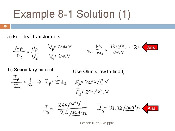
Example 8 -1 Solution (1) 10 a) For ideal transformers Ans b) Secondary current Use Ohm’s law to find Is Ans Lesson 8_et 332 b. pptx
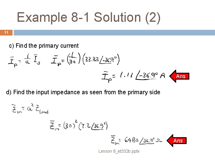
Example 8 -1 Solution (2) 11 c) Find the primary current Ans d) Find the input impedance as seen from the primary side Ans Lesson 8_et 332 b. pptx
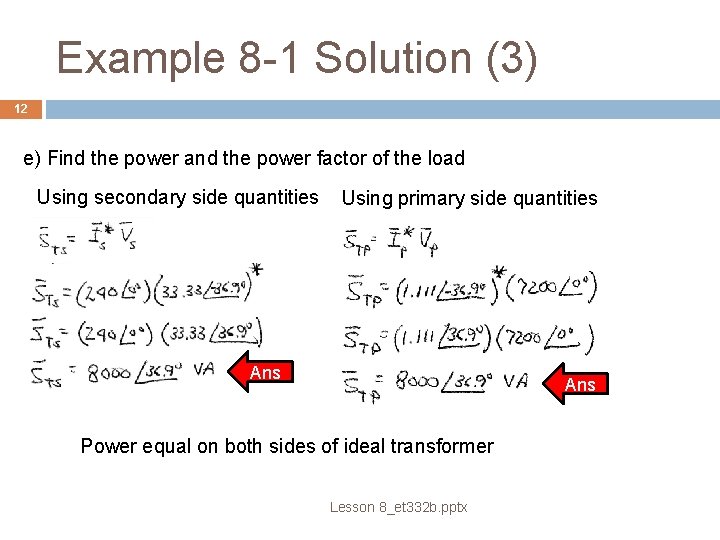
Example 8 -1 Solution (3) 12 e) Find the power and the power factor of the load Using secondary side quantities Using primary side quantities Ans Power equal on both sides of ideal transformer Lesson 8_et 332 b. pptx
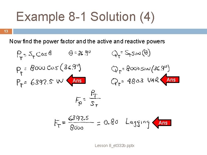
Example 8 -1 Solution (4) 13 Now find the power factor and the active and reactive powers Ans Ans Lesson 8_et 332 b. pptx
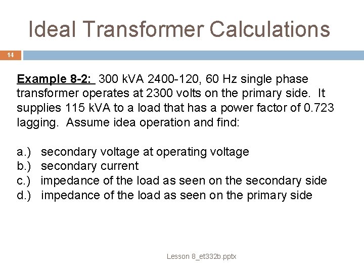
Ideal Transformer Calculations 14 Example 8 -2: 300 k. VA 2400 -120, 60 Hz single phase transformer operates at 2300 volts on the primary side. It supplies 115 k. VA to a load that has a power factor of 0. 723 lagging. Assume idea operation and find: a. ) b. ) c. ) d. ) secondary voltage at operating voltage secondary current impedance of the load as seen on the secondary side impedance of the load as seen on the primary side Lesson 8_et 332 b. pptx
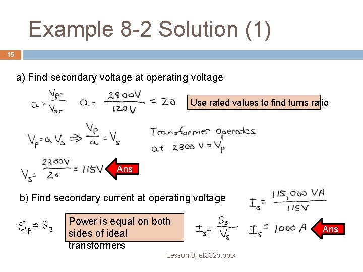
Example 8 -2 Solution (1) 15 a) Find secondary voltage at operating voltage Use rated values to find turns ratio Ans b) Find secondary current at operating voltage Power is equal on both sides of ideal transformers Lesson 8_et 332 b. pptx Ans
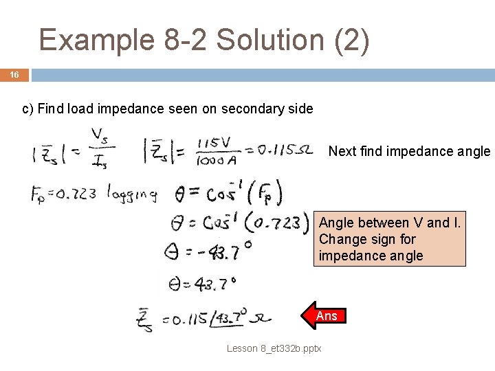
Example 8 -2 Solution (2) 16 c) Find load impedance seen on secondary side Next find impedance angle Angle between V and I. Change sign for impedance angle Ans Lesson 8_et 332 b. pptx
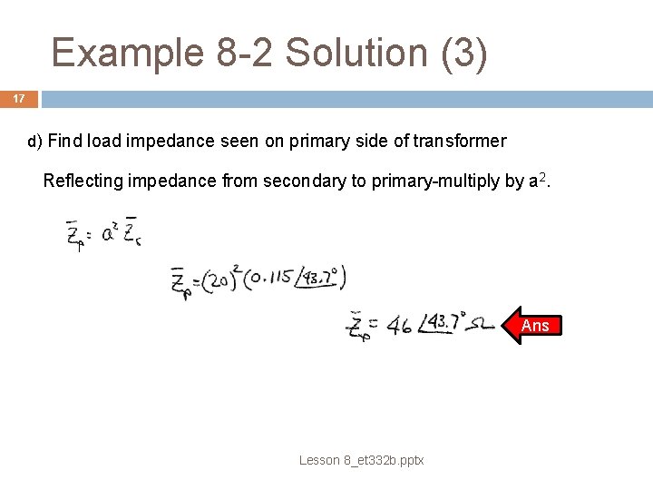
Example 8 -2 Solution (3) 17 d) Find load impedance seen on primary side of transformer Reflecting impedance from secondary to primary-multiply by a 2. Ans Lesson 8_et 332 b. pptx
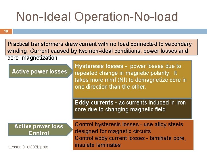
Non-Ideal Operation-No-load 18 Practical transformers draw current with no load connected to secondary winding. Current caused by two non-ideal conditions: power losses and core magnetization Hysteresis losses - power losses due to Active power losses repeated change in magnetic polarity. It takes more mmf (NI) to demagnetize core in one direction than the other. Eddy currents - ac currents induced in iron core due to changing magnetic field Active power loss Control Lesson 8_et 332 b. pptx Control hysteresis losses - use alloy steels designed for magnetic circuits Control eddy current losses - laminate core, insulate laminates
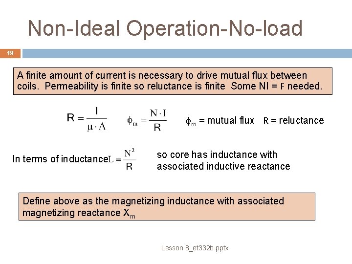
Non-Ideal Operation-No-load 19 A finite amount of current is necessary to drive mutual flux between coils. Permeability is finite so reluctance is finite Some NI = F needed. fm = mutual flux R = reluctance In terms of inductance so core has inductance with associated inductive reactance Define above as the magnetizing inductance with associated magnetizing reactance Xm Lesson 8_et 332 b. pptx
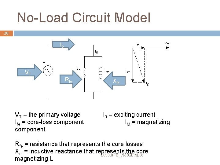
No-Load Circuit Model 20 Io VT Rfe VT = the primary voltage Ife = core-loss component XM I 0 = exciting current IM = magnetizing Rfe = resistance that represents the core losses Xm = inductive reactance that represents the core Lesson 8_et 332 b. pptx magnetizing L
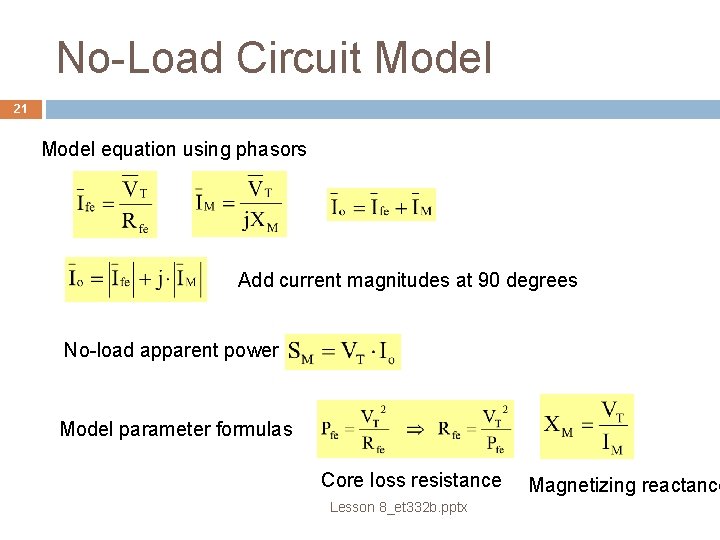
No-Load Circuit Model 21 Model equation using phasors Add current magnitudes at 90 degrees No-load apparent power Model parameter formulas Core loss resistance Lesson 8_et 332 b. pptx Magnetizing reactance
No-Load Transformer Example 22 Example 8 -3: Computing the values of magnetizing reactance and core loss resistance. A 50 k. VA 7200 -240 V, 60 Hz single phase transformer is operating with no load. With the primary connected to a 7200 V system, it draws 248 W and has a power factor of 0. 187 lagging. Find: a) the exciting current and its components b) the magnitudes of magnetizing reactance, XM and core loss R c) Repeat parts a and b if the transformer is energized from the secondary (low voltage) side. Lesson 8_et 332 b. pptx
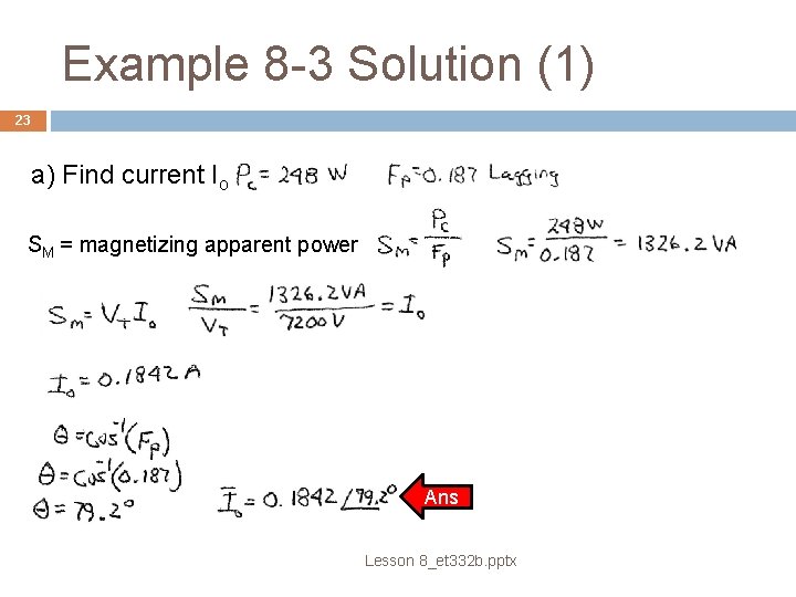
Example 8 -3 Solution (1) 23 a) Find current Io SM = magnetizing apparent power Ans Lesson 8_et 332 b. pptx
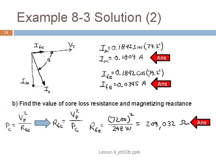
Example 8 -3 Solution (2) 24 Ans b) Find the value of core loss resistance and magnetizing reactance Ans Lesson 8_et 332 b. pptx
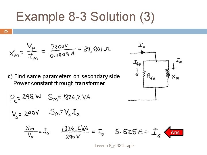
Example 8 -3 Solution (3) 25 c) Find same parameters on secondary side Power constant through transformer Ans Lesson 8_et 332 b. pptx
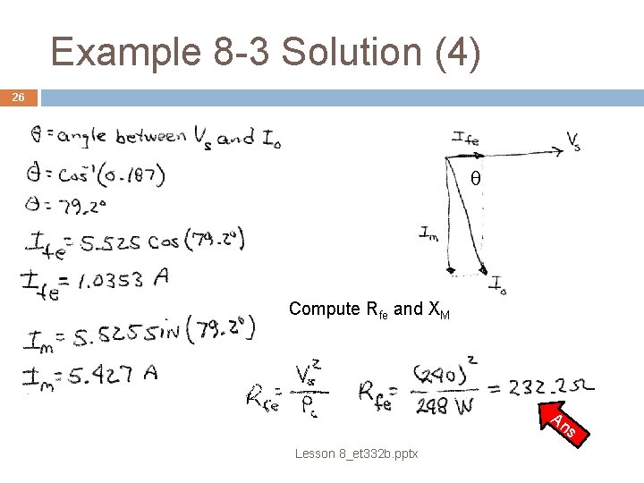
Example 8 -3 Solution (4) 26 q Compute Rfe and XM An s Lesson 8_et 332 b. pptx
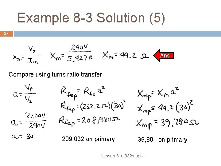
Example 8 -3 Solution (5) 27 Ans Compare using turns ratio transfer 209, 032 on primary 39, 801 on primary Lesson 8_et 332 b. pptx
28 ET 332 b Ac Motors, Generators and Power Systems End Lesson 8: Ideal Transformer Theory and Operation Lesson 8_et 332 b. pptx
- Slides: 28